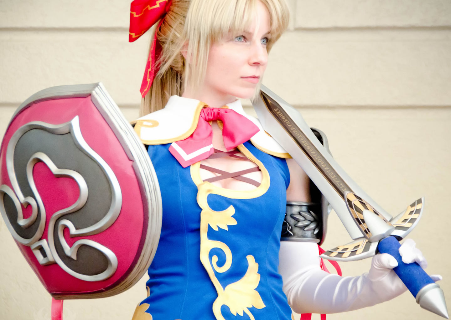
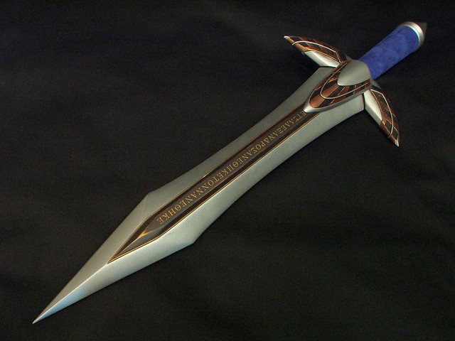
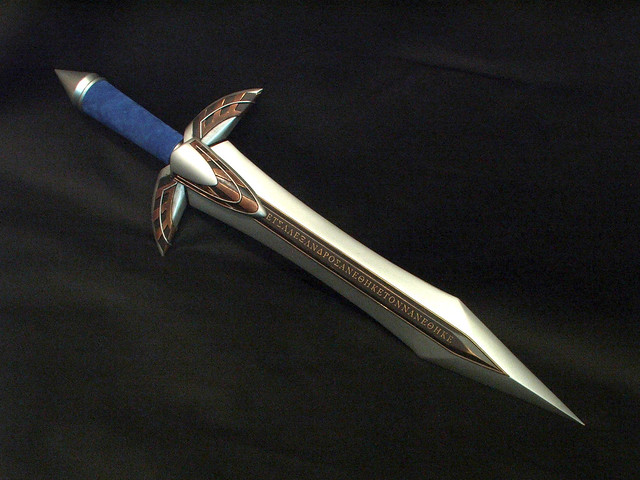
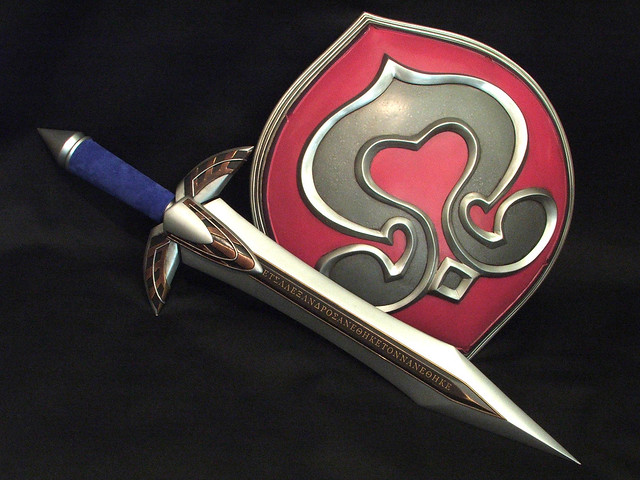
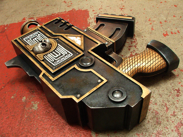
Cassandra’s Digamma Sword
Yes, MORE SoulCalibur love!
Having already created Cassandra’s Nemea Shield and Pauldrons, I rounded out the set with her Digamma shortsword.

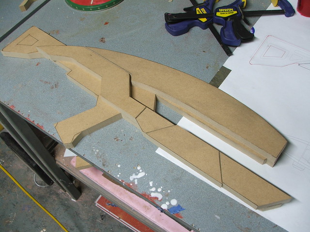
Its a bit of an odd piece – the blade is extraordinarily thick and decorated with raised Greek lettering. After gathering a lot of reference, I created a set of blueprints to reference during the build.
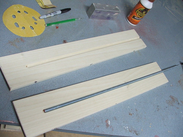
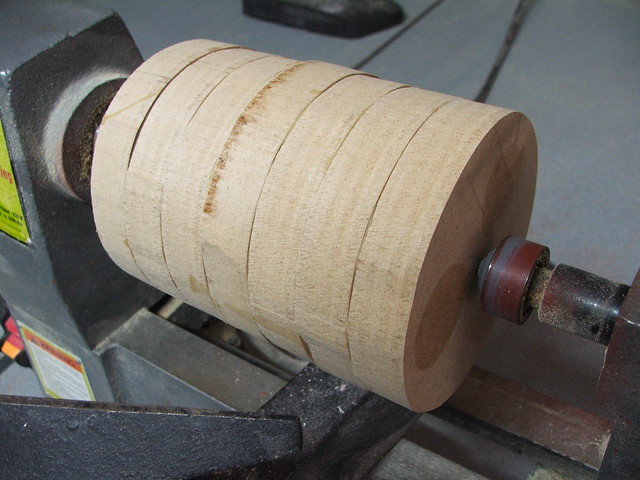
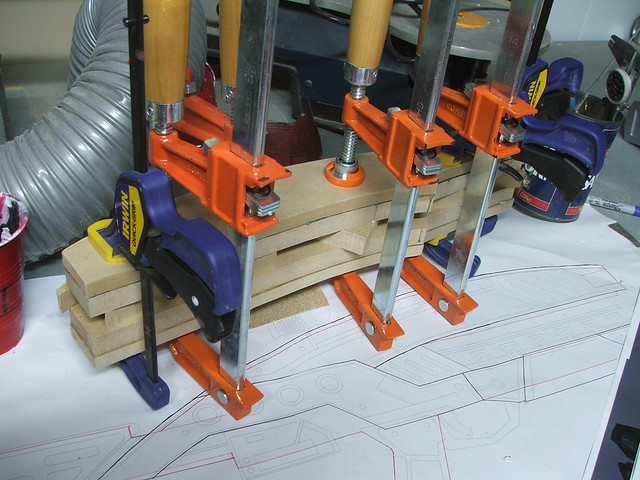
A friend of mine in propmaking, BlindSquirrel makes a TON of anime and gaming swords. One of his preferred methods for blade shaping is to glue two sheets of wood across a steel core. Blatantly stealing this process, I laminated two sheets of poplar around a 3/16″ steel threaded rod. The threads will help the glue adhere to the core better than they would if it were just a smooth piece.
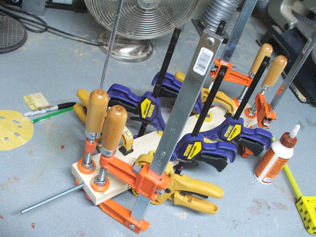
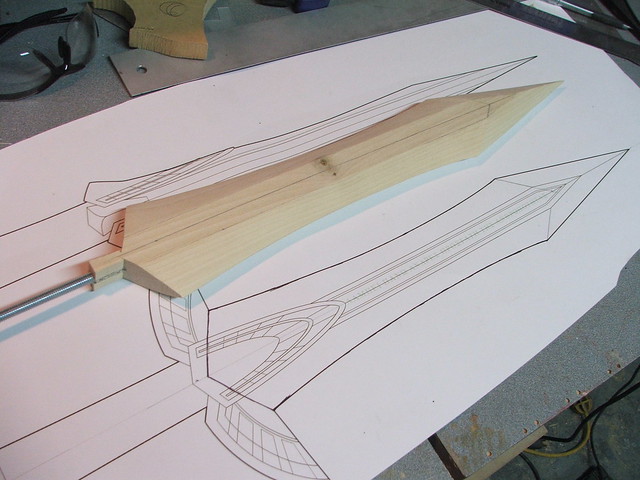
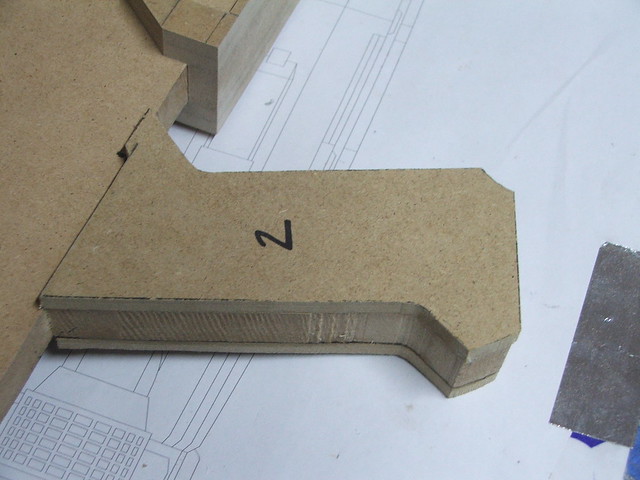
After the glue dried, I cut the basic shape of the blade with my bandsaw
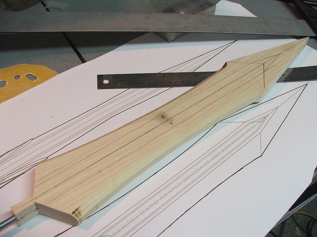
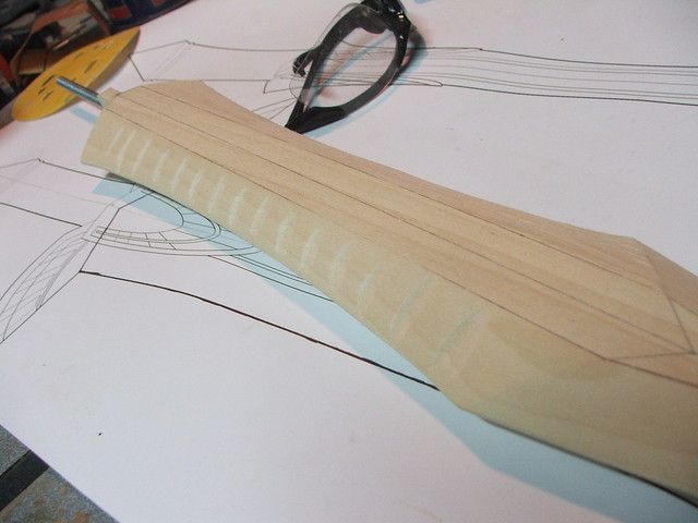
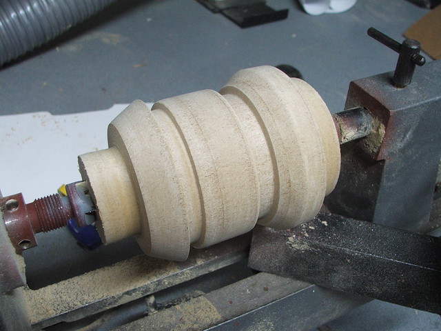
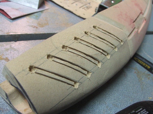
The taper of the blade edge was done mostly with a belt sander, with further refinement performed with a sanding block and 80-grit paper.
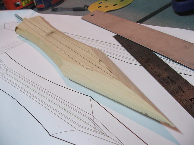
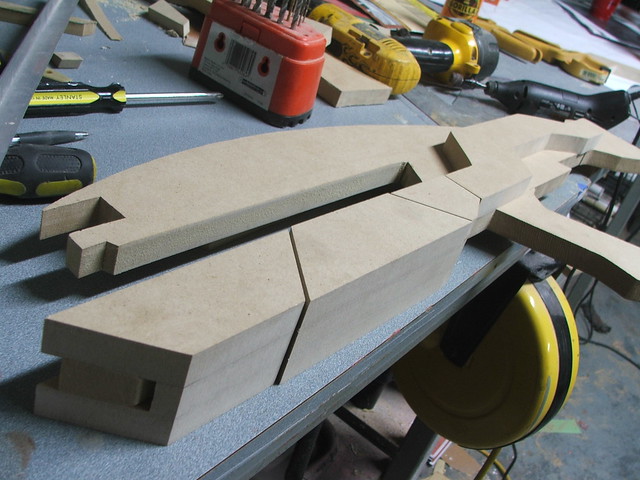
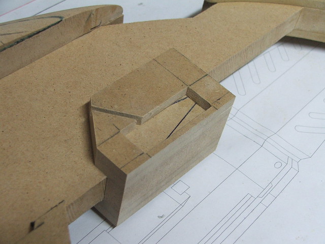
In order to make sure the depth on the side cuts was uniform, I used my dremel tool to cut small “depth fillets” in the side of the blade. When all of these were sanded flush with the rest of the bevel, I knew I had the correct angle I needed.
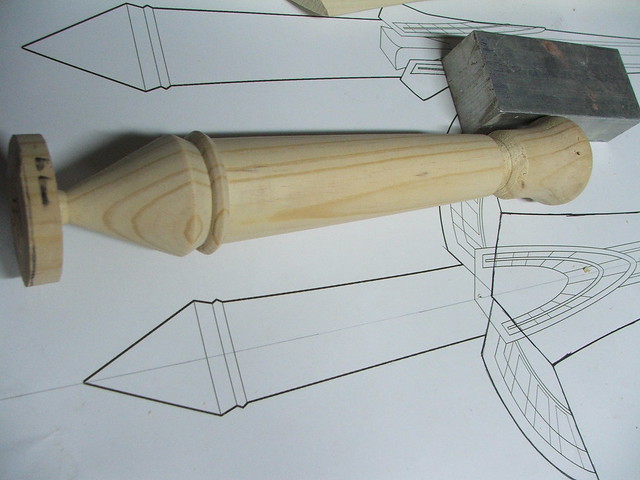
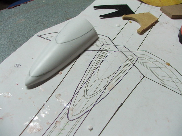
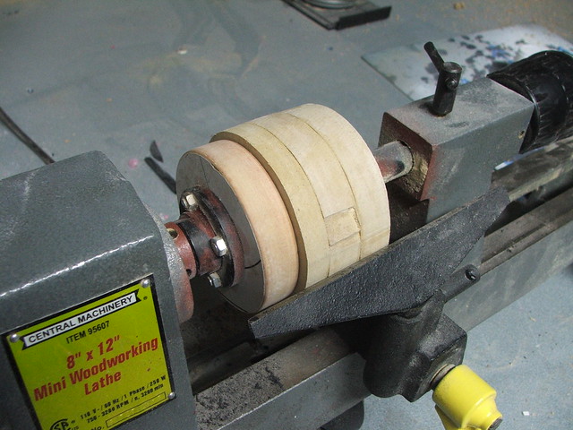
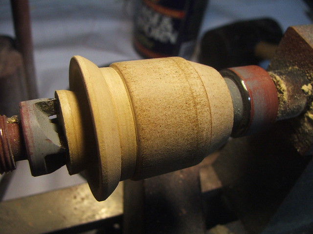
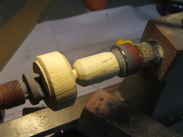
For the handle and pommel, I used a piece of pine turned on my lathe. A small step was placed at the end to make a lip for the eventual leather wrapping. The end piece was sanded to a point by hand after turning.
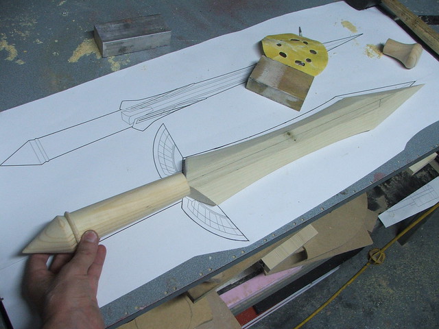
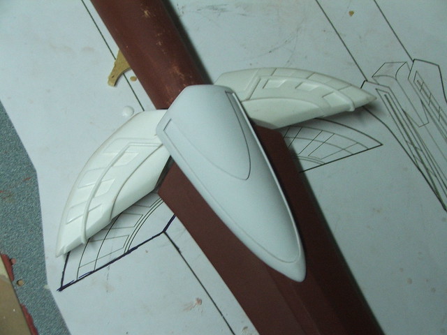
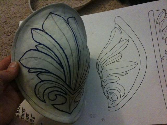
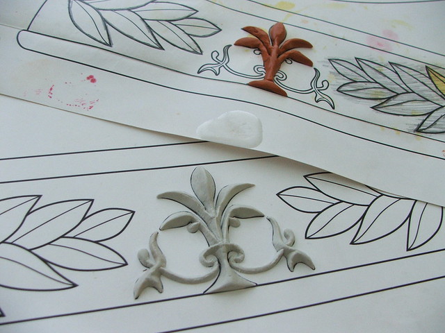
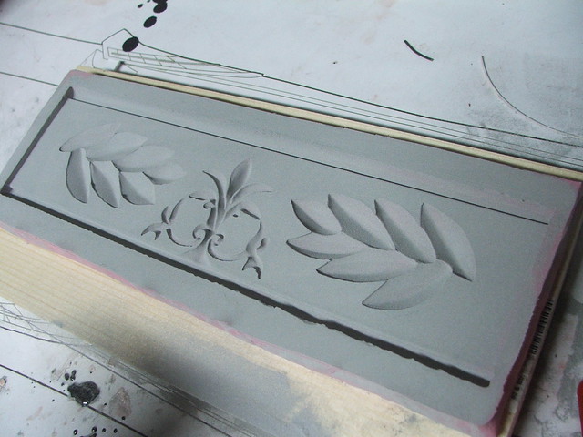
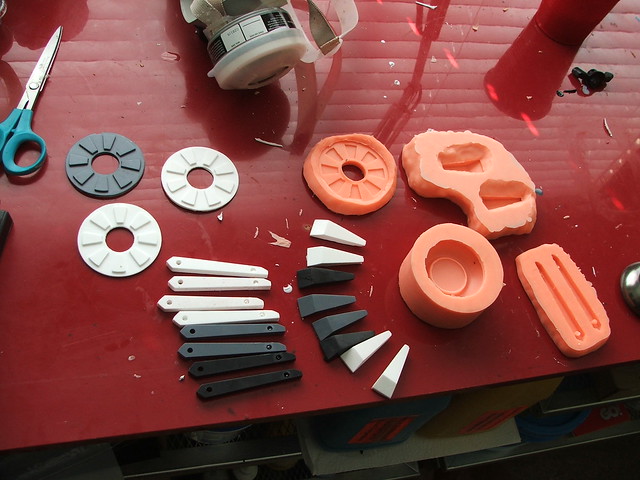
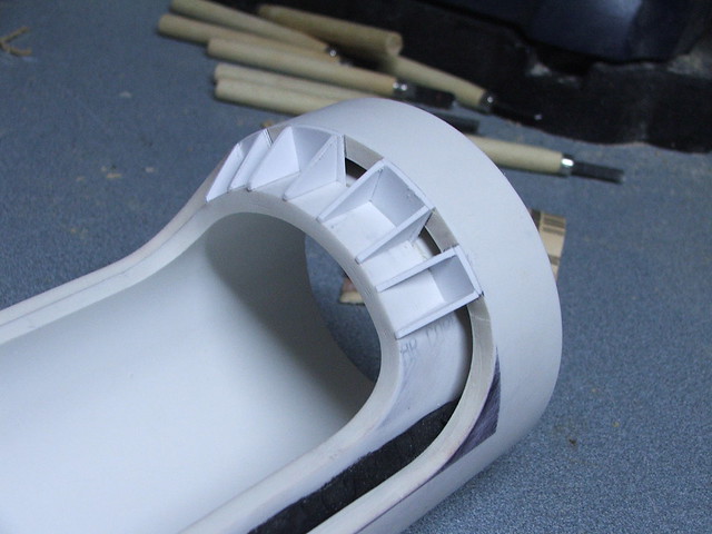
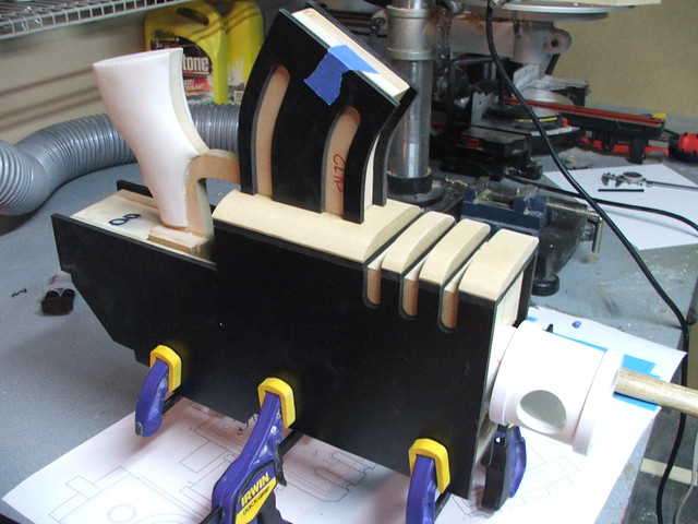
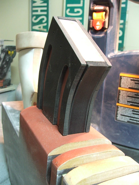
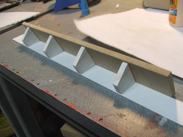
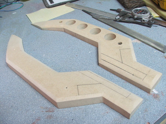
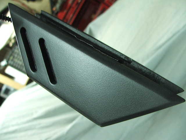
For the cross guards, I decided to sculpt one piece out of wood with styrene accents, then mold it for an identical opposite side copy. Starting off, I took some of the scrap poplar from the blade leftovers and cut it to the shape of the wing-a-ling.
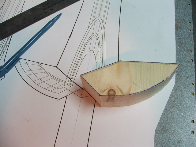
This was shaped on the beltsander until I had the desired teardrop profile.
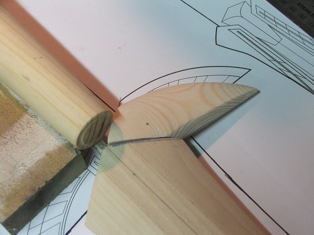
By using blue painter’s tape, I was able to trace the pattern on the blueprint, then transfer it to the cross guard.
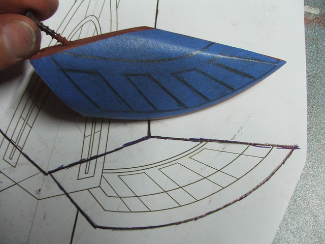
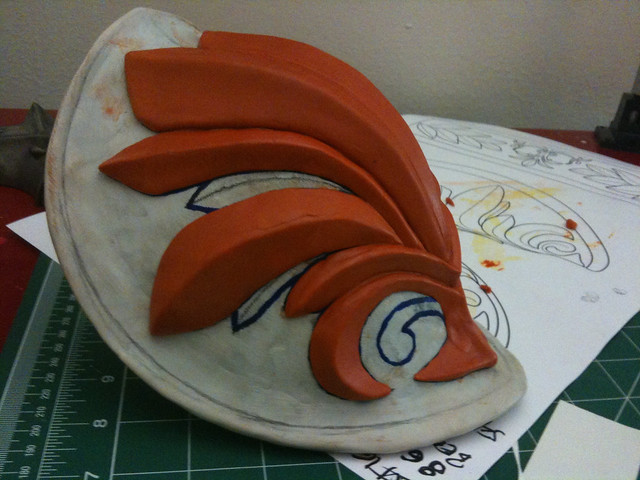
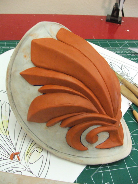
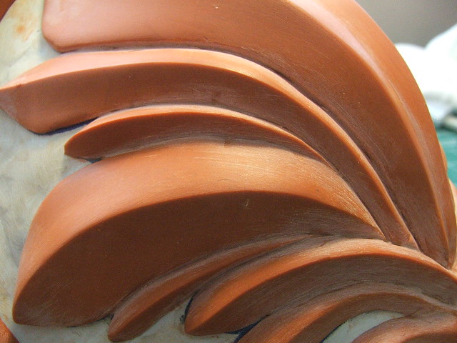
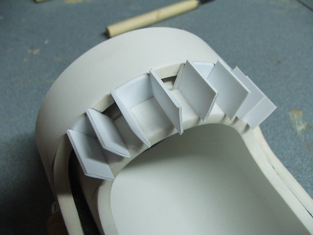
For lack of a better term, I called these the “feathers.” After removing the tape from the crossguard, I laid it over a piece of sheet styrene and trimmed the pattern out. The styrene parts were heated and glued onto the surface of the wooden master.
Symmetry!
The last detail was the raised line across the feather pieces, which was made from half-round styrene
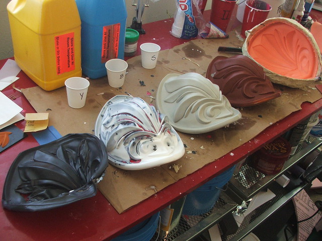
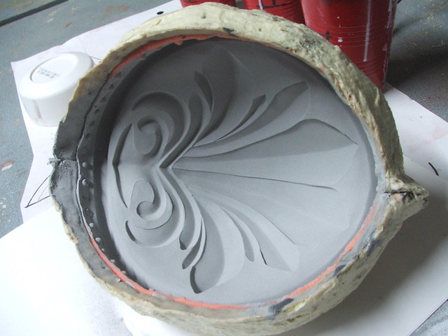
Onto molding and casting! I used Mold Max 30 silicone and SmoothCast 300 resin to produce the duplicates.
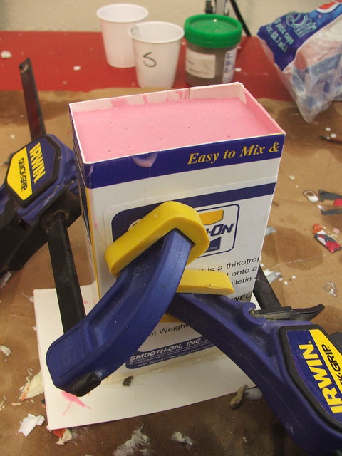

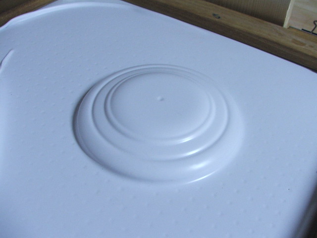
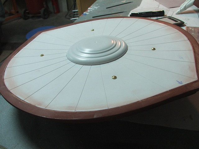
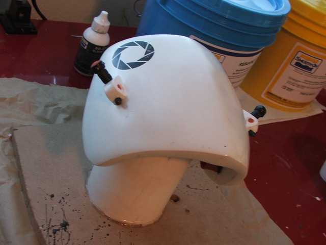
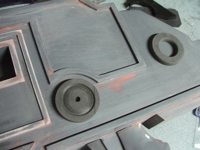
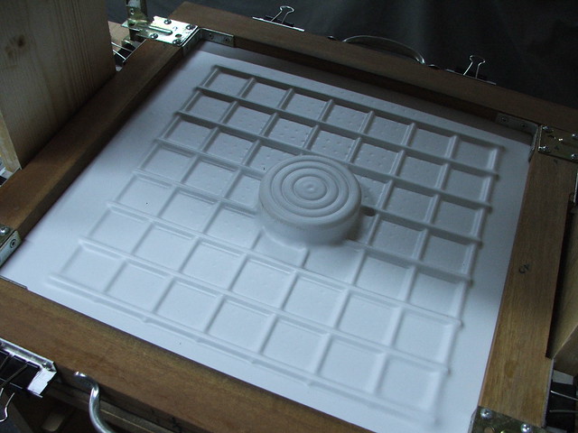
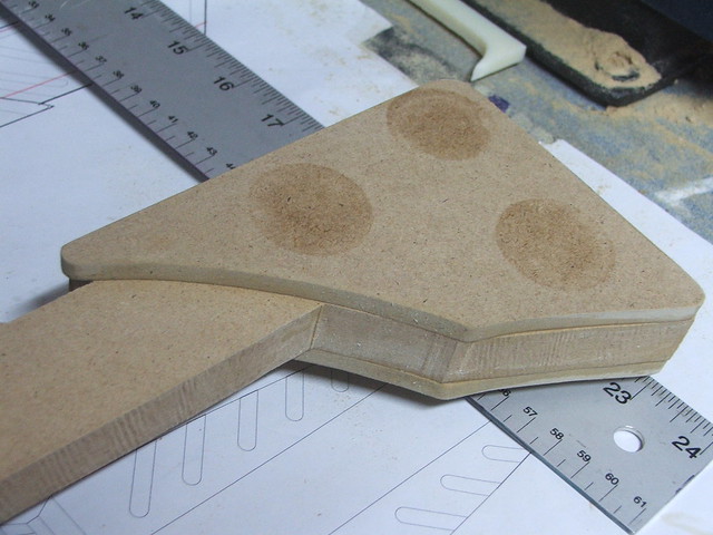
The crossguard cap (can you tell I’m just making words up?) was molded in a similar way, as I needed two of these as well. I started by making a master in MDF, then vacuumforming the shape in .060″ styrene.
You can see the master in the back of this shot. The shape in the front is the start of Cassandra’s Medallion she wears on the bottom of her blouse.

Here’s the piece trimmed from the styrene. I pulled two of these and set them inside one another to create the beveled interior edge.
And after adding more styrene details like with the wings, it was ready for molding!
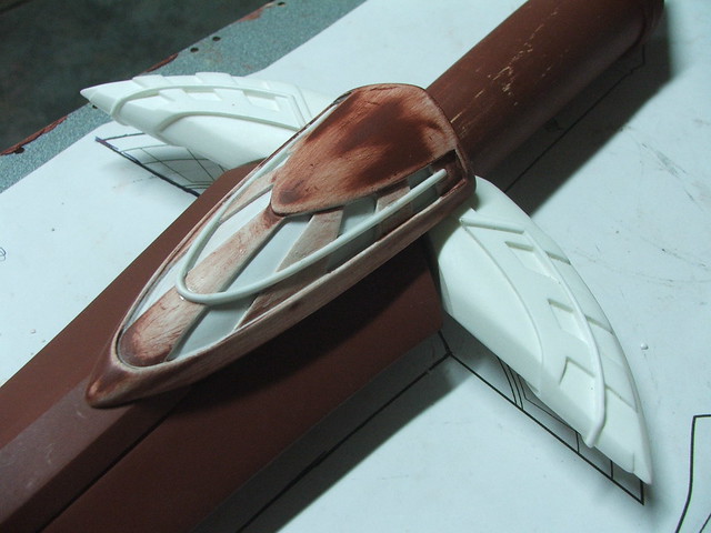
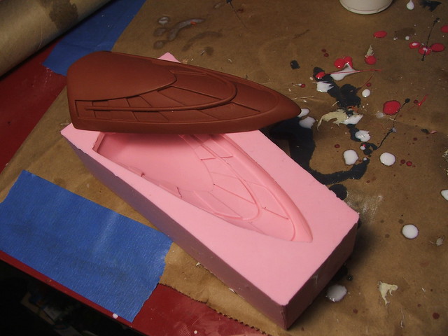
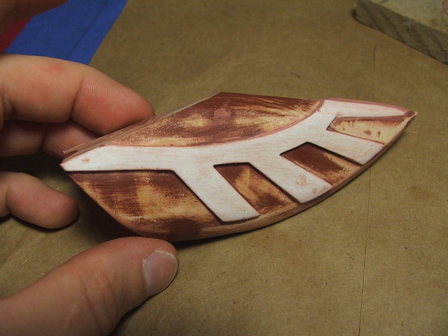
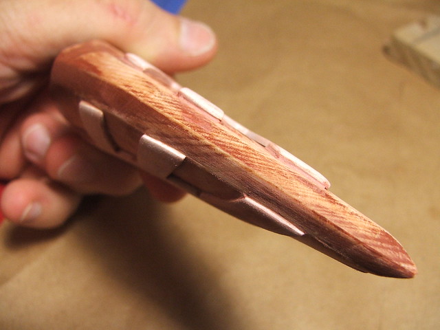
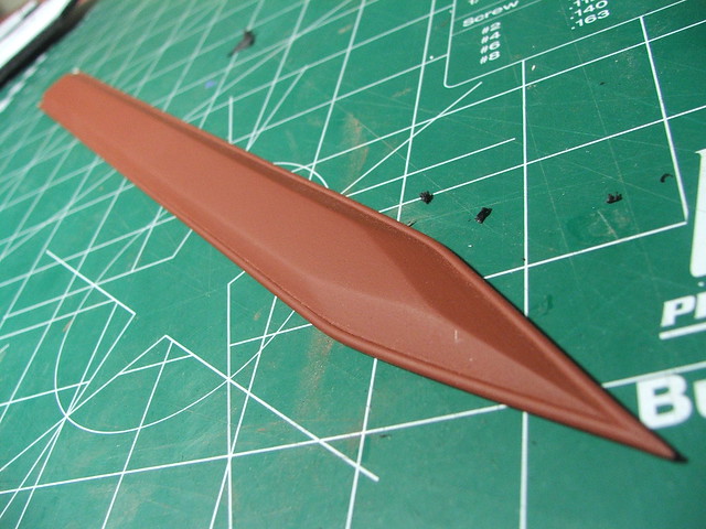
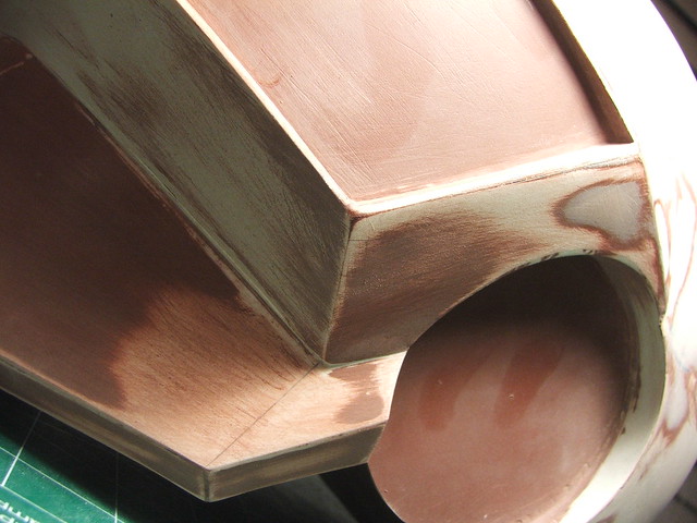
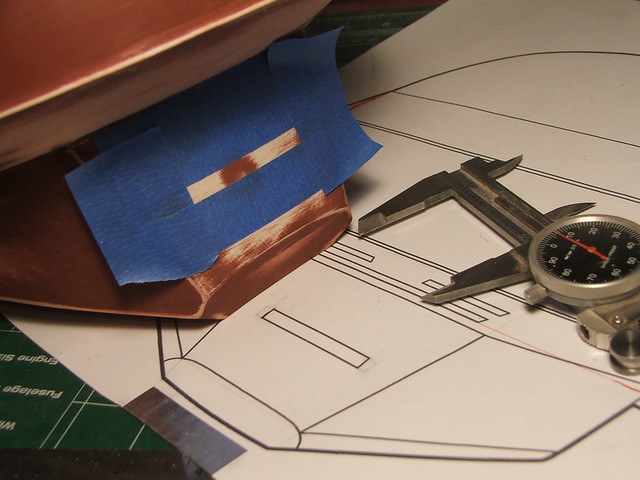
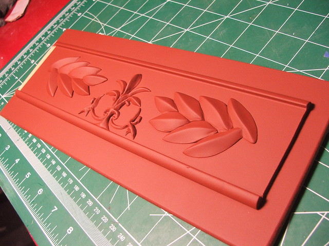
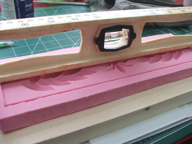
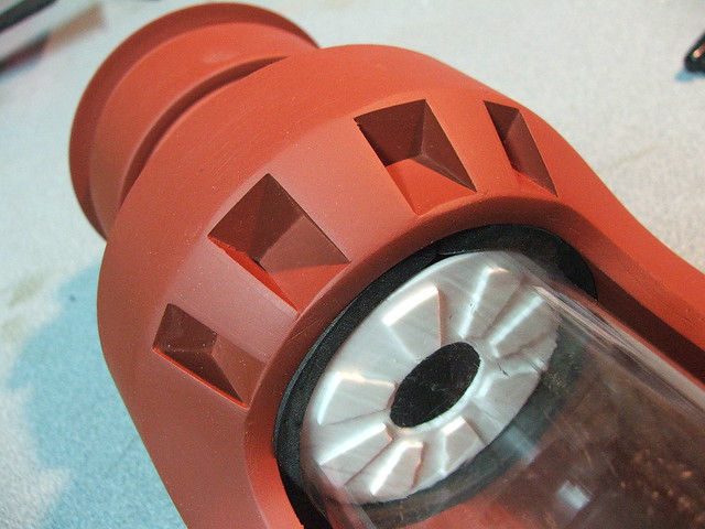
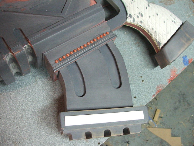
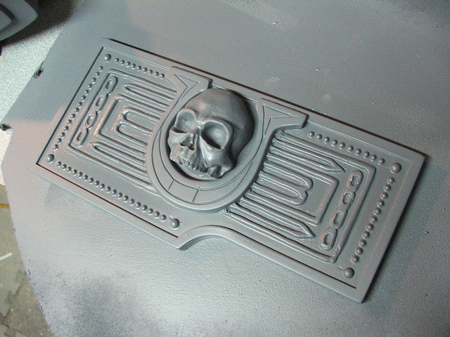
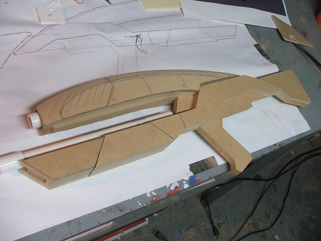
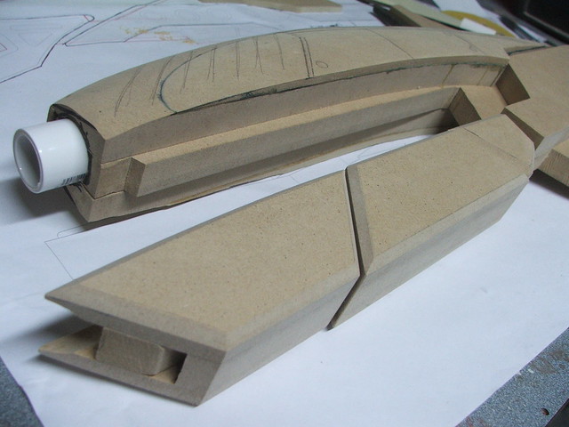
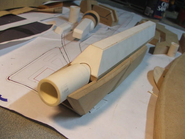
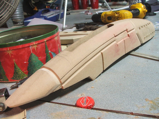
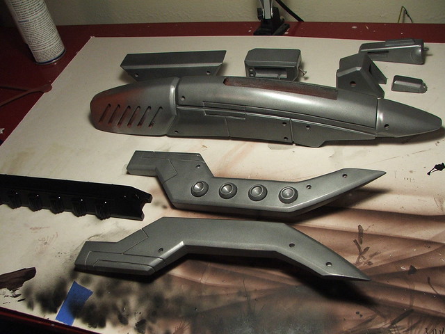
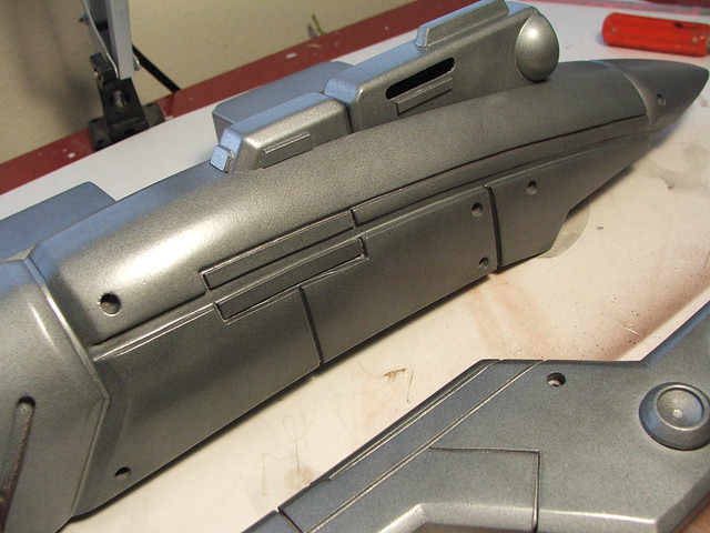
The long raised detail on the center of the blade was made out of a thin strip of sintra, shaped on my belt sander. The small bead along the edge is more half-round styrene.
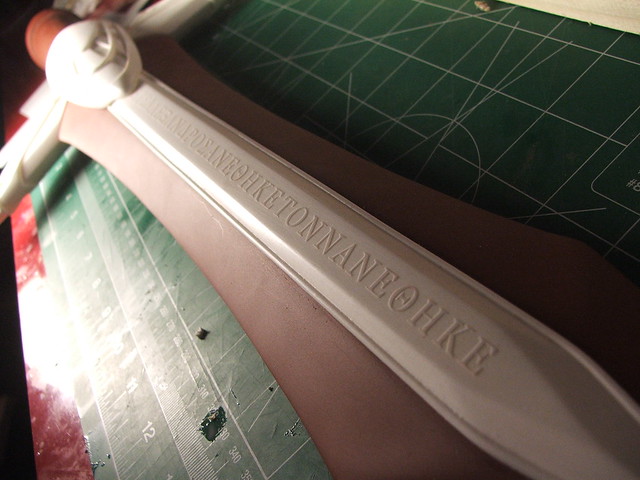
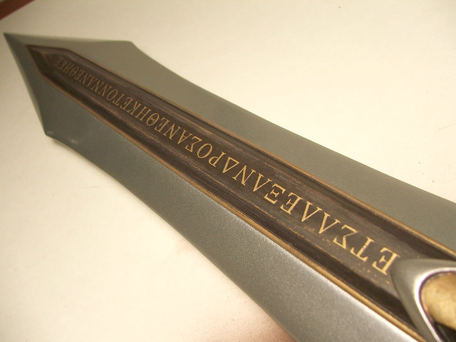
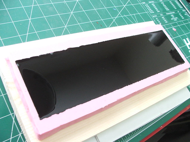
Hand carving the Greek lettering on this piece would require a level of precision I don’t possess, so I employed a neat trick I’ve seen some modelbuilders use. To make raised panels on small model ships, sometimes a sheet of vinyl will be cut into squares and molded over, making a very lightly raised edge in the cast piece.
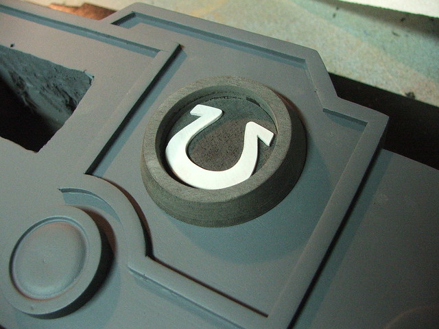
I created a set of vinyl decals based off some of the game art from SoulCalibur 3 (references for IV were almost impossible to read!) and laid the lettering out onto the master. Don’t bother translating; its all gibberish.
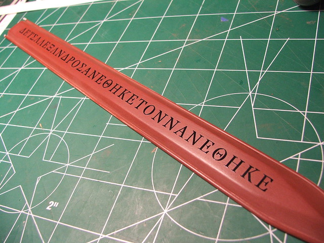
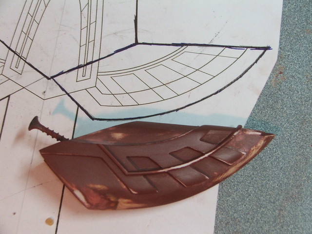
This piece was then molded in more Mold Max silicone. Perfect detail!
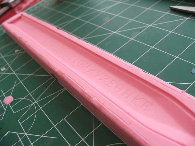
The final pull shows the results. Crisp lettering with each pull, and SO much easier than trying to inscribe a uniform set of lettering into both sides by hand!
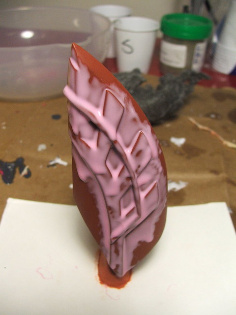
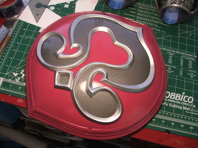
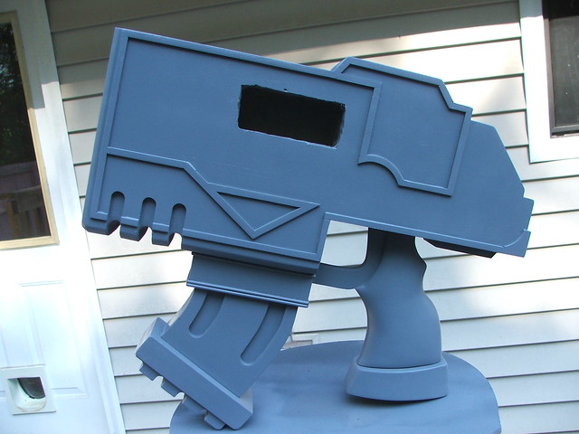
Base painting was done with Krylon hammered silver for the blade, and Testors Antique Gold for the raised center and hilt pieces. Shiny!
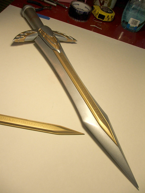
A bit too shiny, really. To get the lettering to stand out more, I airbrushed acrylic over the center section, then wrapped a piece of 600 grit wet sandpaper around an aluminum block. By gently going over the tops of the letters, the gold was brought out from the brown “weathering” and stood out much better.
The rest of the sword was treated to similar weathering and accent colors.
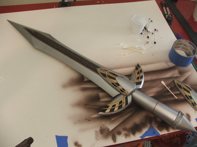

The final element was a blue-leather wrapped handle and some light dirt accents in the recessed areas of the hilt and blade accents. I haven’t built many bladed weapons, but I really love how this one has turned out.
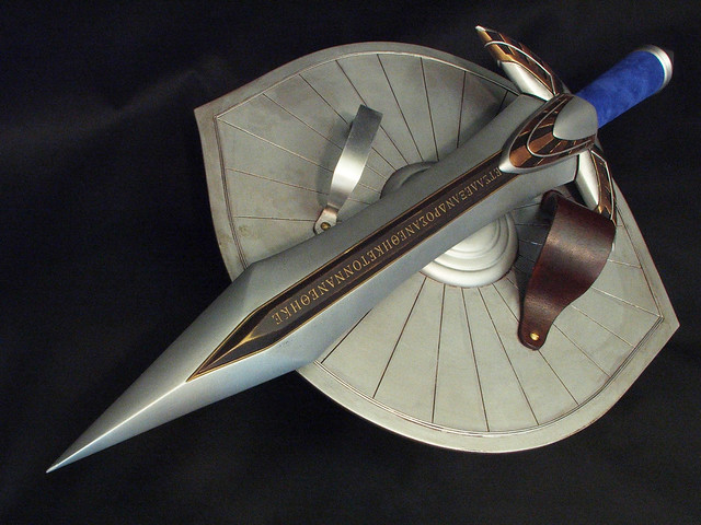
And together with the Nemea shield!
Higher resolution images are available on my flickr page. Thanks for reading!

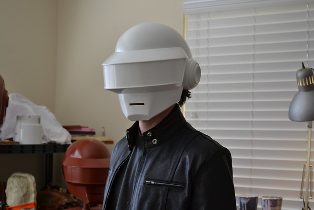
Daft Punk Helmet (Thomas): Part 1
I suppose it was an inevitability. Just like you can’t have Link without Zelda, Big Daddies without Little Sisters, and Master Chief without Cortana (well, except for that stretch in Halo 2, but we can all agree that was the weakest one in the trilogy) my Guy helmet was only half of the full set. After catching my breath from the holidays, I got to work on Thomas in early January.

I started out by drawing up some blueprints, taking note this time to do more than 2 views. The width on the Guy helmet was something I struggled with, and more detailed blueprints would have alleviated that.
I learned a lot from Guy, most specifically what not to do. Often times, these are the most potent lessons of all. I started this project with a lot more experience, which has shortened the construction times of many things considerably. This bucket won’t be knocked out in a month, but I think I can take a pretty good chunk out of my 1.5 year build time from the last helmet!
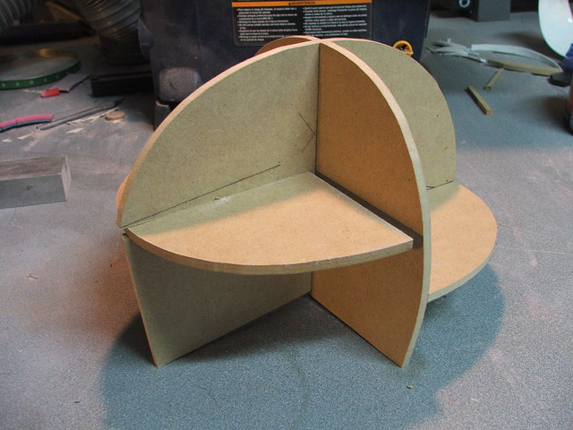
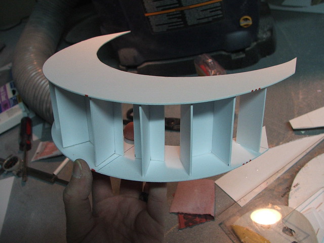
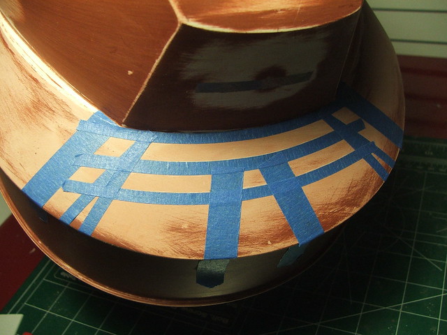
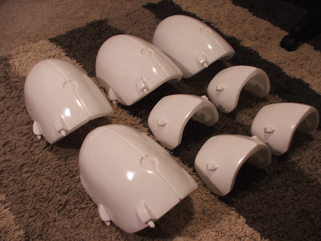
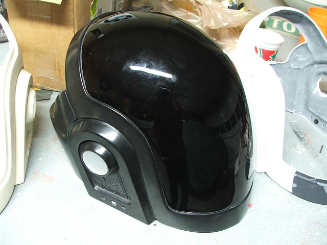
Right off the bat, things changed. The paper template I made for Guy was lacking in several ways. For Thomas, I created sectioned ribs from 1/4″ MDF. These built on top of one another to form a sort of interlocking skeleton.
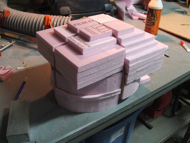
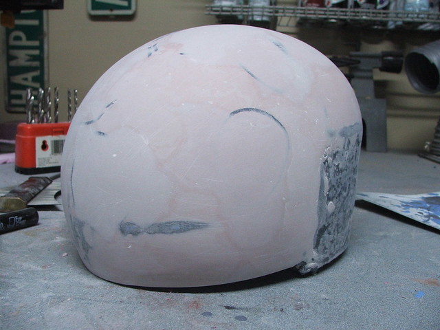
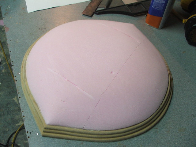
The cavities in the MDF frame were filled up with polystyrene insulation foam, carved to a rough shape with a coping saw, then sanded to the general shape of the dome with an orbital sander.
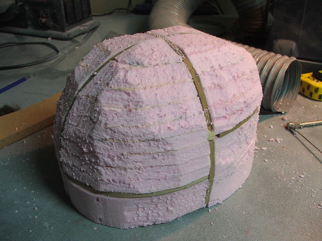
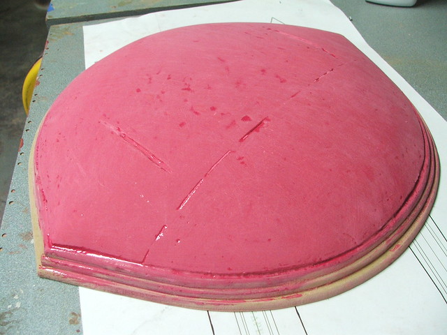
Pink foam acts badly when exposed to polyester resins (bondo, fiberglass, etc) so it was sealed with a few coats of urethane casting resin. This gives me a tough, lightweight shell to work on top of without worrying about it dissolving the foam base.
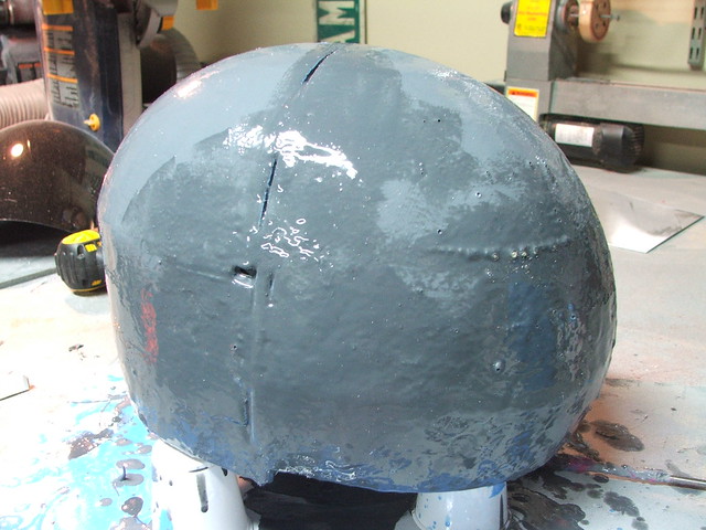
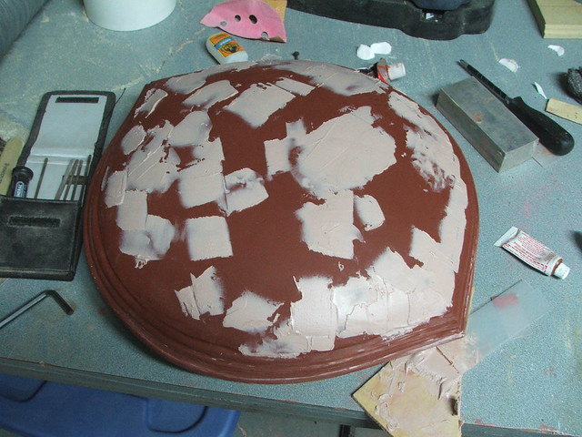
After scuffing the surface of the foam with some 60-grit sandpaper, I coated the urethane resin with a few bondo passes to refine the shape of the dome. The visor and chin sections will be built out later, but getting the base shape correct was the biggest goal at this point.
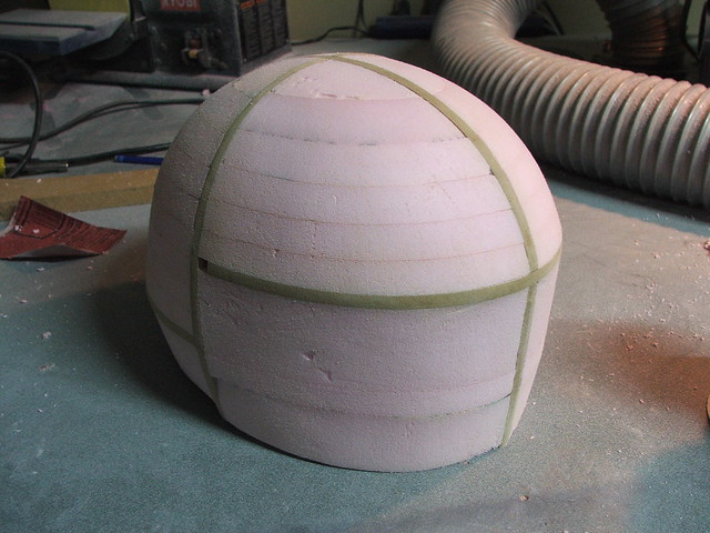
A contour gauge, passed down from my grandfather, makes getting the compound curves of the surface much easier. Take the shape of one side, flip it over to the mirrored side, and add/remove material as necessary…
…and there was quite a lot of this add/remove process.

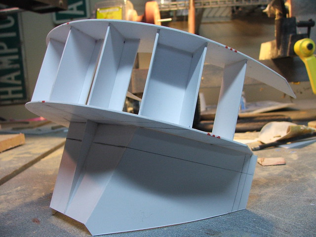
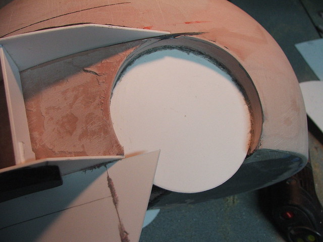
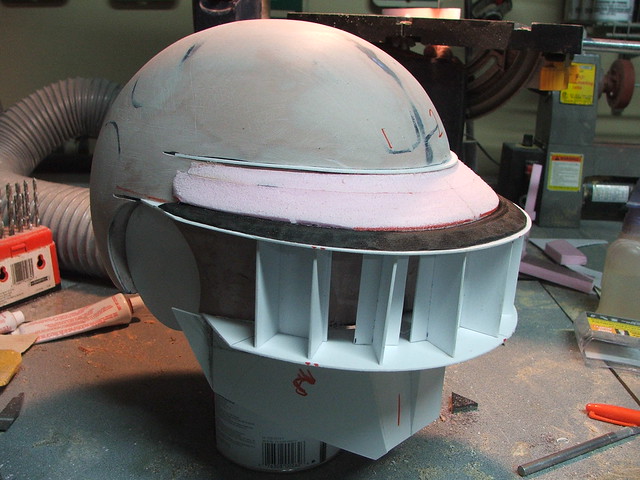
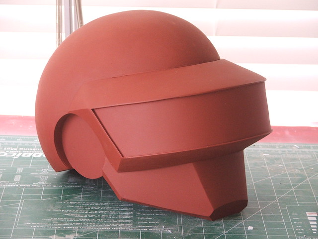
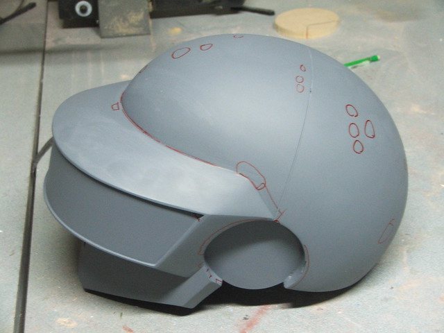
My plan for the visor was to make the shape as a standalone piece, adhere it to the finished dome, then blend the upper and lower sections in. The upper and lower sections were cut from styrene, and spaced apart with upright inserts.

The dome was then slotted to hold the visor sections in place so i could check the symmetry and alignment.
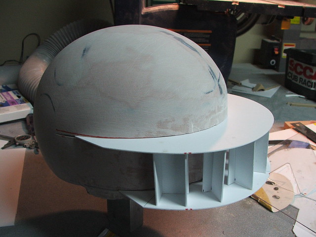
More styrene was used to make the “chin” and “cheek” sections, which rounded out the front removable section of the helmet.
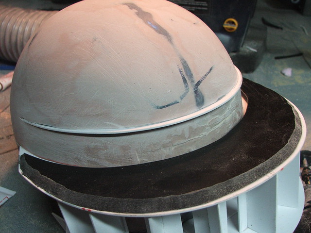
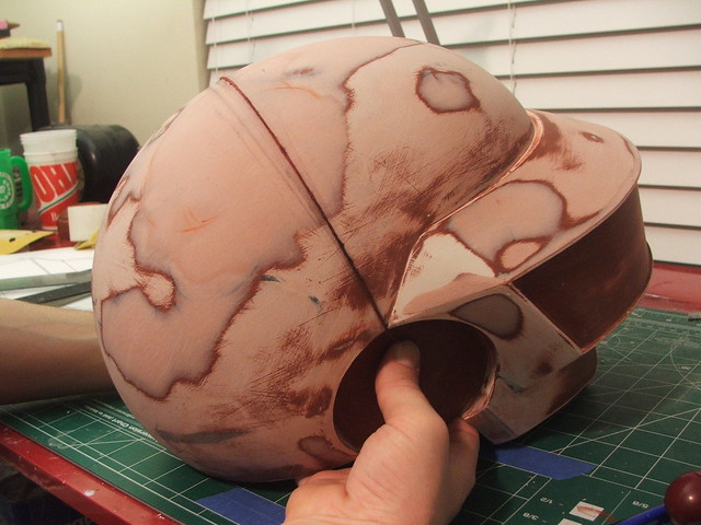
Now that the visor had a place to sit, I could build the ears for the helmet. Thomas’ ears change pretty frequently on his helmet from version to version, so I decided to make the ears on this helmet removable. In the future, I can make new pucks and replace the ears in the helmet to represent a Discovery, Tron, or Human After All style helmet.
The ears themselves were lathed from a stack of MDF. For this helmet, I decided to make the ears “Electroma” style.
Quick mockup!
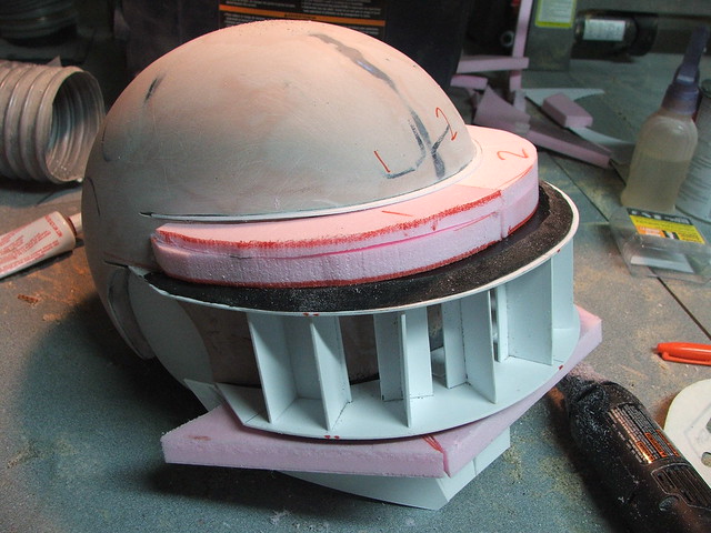
To fit the ears, recesses were carved into the foam base. Styrene “caps” were placed over the rough edges, and the interior surface was smoothed out to make a tight fit with the ear puck.
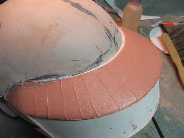
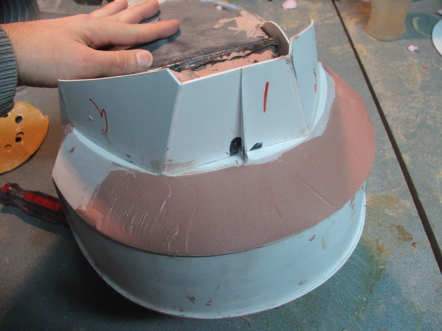
Getting back to the visor, I started working on blending the edges upward and downward into the front of the helmet. In order to make sure everything ended at the same point, I added a thin ridge of styrene at the upper edge of the visor intersection with the helmet dome.
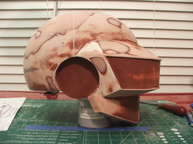
Much like the domed shape, polystyrene foam was placed in these cavities then sanded to shape.
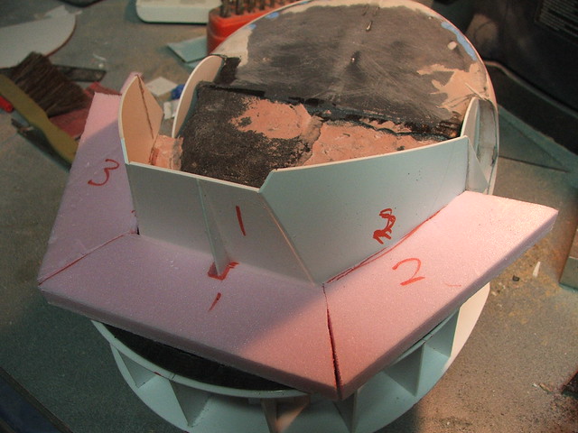
After coating the foam, I skimmed bondo over these bevels and sanded them to a smooth curve. I also added the front and side visor sections in as well at this point, with more styrene.
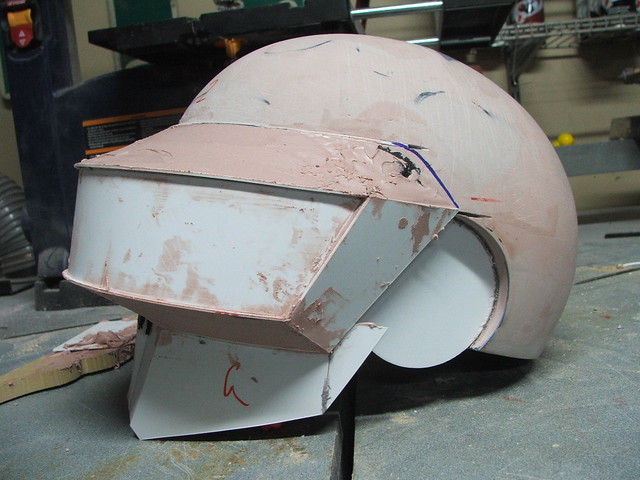
Details around the edges and at the chin, which were harder to accomplish in bondo, were made in Apoxie Sculpt.
The remainder of the beveled edges around the bottom of the chin were made with about a hundred paper templates, then eventually trimmed out and glued into place with styrene.
Even though the helmet was a solid piece, I couldn’t resist a little photoshop testing. I set up a tripod and the timer on my Nikon, then set up the helmet on an adjacent tripod and took a few shots. By standing in the same spot and snapping a couple pics of myself, i was able to get a pretty good idea of the scale. It was perfect!
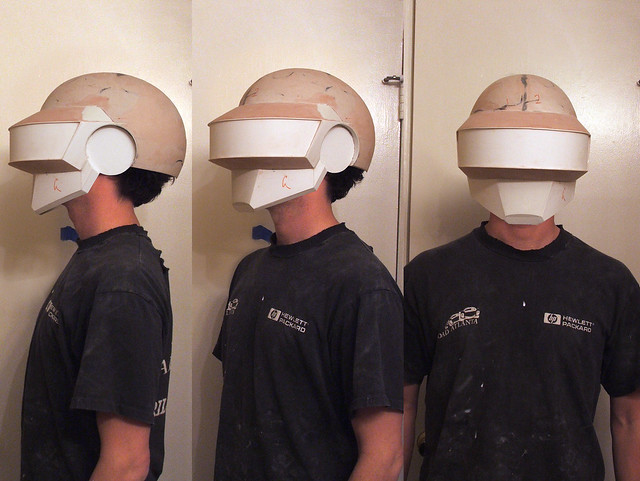
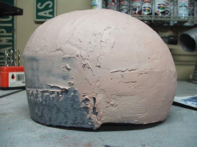
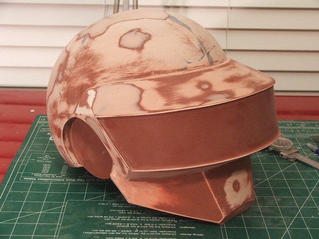
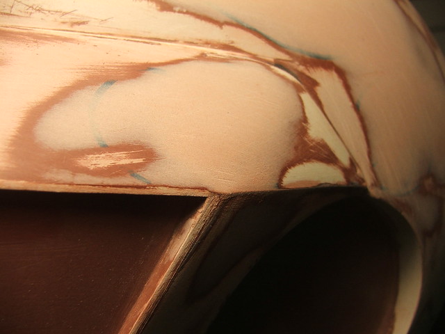
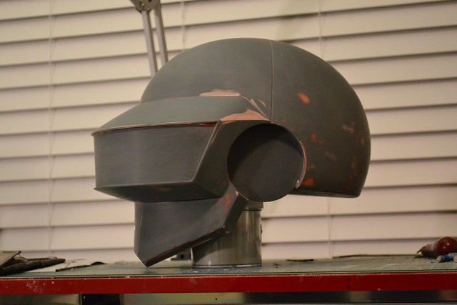
At this point, it was a bit difficult to see problem areas that needed filler, so the bucket was painted with some brown primer. Having a uniform surface makes fixing problem spots much easier.
After a few thin skim passes with bondo, details like the sharp visor edges were refined.

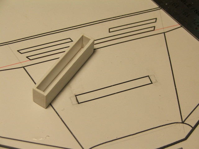
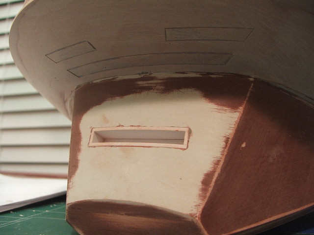
For the mouth of the helmet, I made a styrene box and countersunk it into the chin of the helmet. When castings are pulled, all you just need to hit the backside of this cavity with a dremel to open the mouth up – no tricky carving necessary!
The lower “nose vents” were scribed into the bondo with an etching tool. These didn’t get the same styrene box treatment as the mouth, because making those curved edges would have been a solid pain. For these, some hand-sanding later on down the road will be necessary.

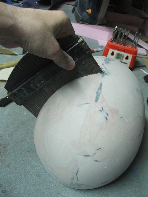
There’s a seam line that runs from ear-to-ear on the top of the helmet that was a bit tricky to get right. I tried scribing this line with a tape stripe at first, but it ended up being very curvy even after several tries. I eventually figured out that using a piece of string yielded a perfectly straight result.
For some reason, this is my favorite look.
But all things must change! After another primer pass, a few small areas were marked for very thin spots of filler.
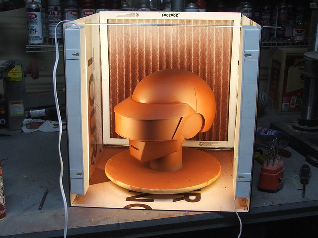
Despite the freezing weather in January, I was able to get these primer coats on thanks to my new portable spray booth. This was built mostly from scraps, but it is a fantastic addition to my shop. Now I can paint in the rain, at night, even in the cold with a space heater!
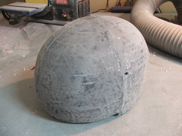
After the last coat of primer, it was time for the super-awesome-fun-wetsanding stage! I started with a sponge to get the shape as uniform as possible, then moved up from 400, 600, then 1,000 grit sandpaper.
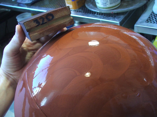
To get the form as smooth as possible in anticipation for the molding process, the primer was buffed to as mirror-shiny as primer gets.
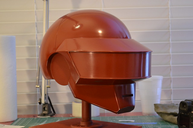
Total time to build the completed master this time was only 4 weeks! Seeing as how Guy took me 5 months, I’d say I’m actually starting to figure out what I’m doing here.
More build pics, and higher resolution, available on my flickr page! As with the last project, this will be broken up into several sections. Look forward to steps 2 and 3, Molding/Chrome and Electronics. If you’re interested in getting more play-by-play updates, check out my Facebook page. I try to post as often as possible when I have new work to show.
This one is going to be a whole new level from my last build. Check back soon for more, and hope you enjoy the read!

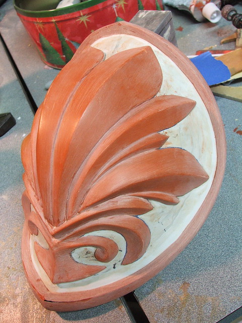
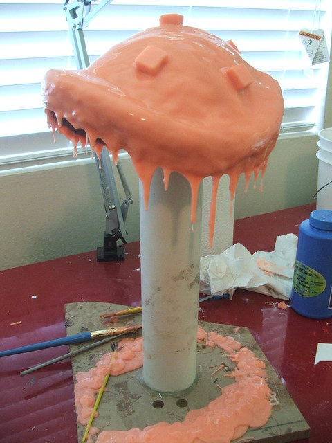
Cassandra’s Nemea Shield
A continuation on a theme, as it were. I’m kind of backlogged with a few entries I need to write; this project was actually finished in September 2010. As I mentioned in the Cassandra’s Pauldron’s post, my original project was to make the Digamma Sword and Nemea Shield from Soul Calibur IV. This post will detail the shield construction.
Blueprints! Again, drafted in Adobe Illustrator and printed full scale. Cassandra’s shield doesn’t actually have any mounting points in the game – no handle and no strap – so I had to make those up. The ones pictured here changed quite a bit before they were final.
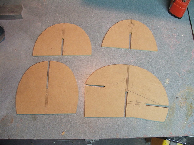
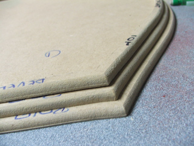
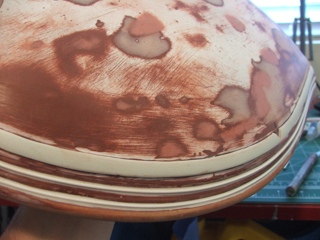
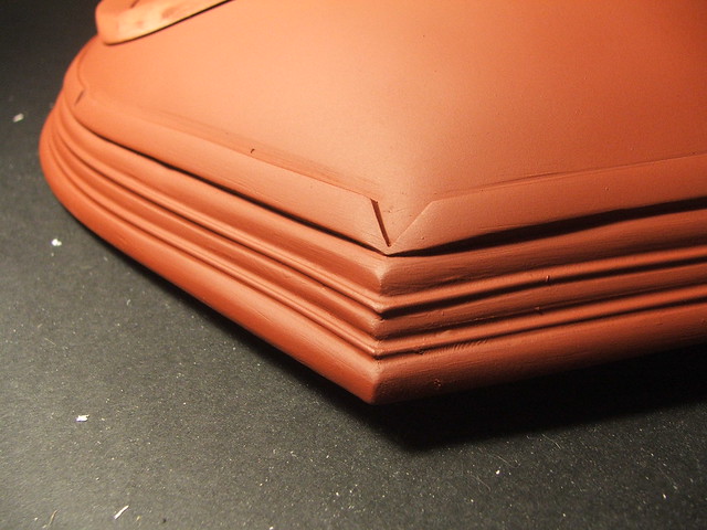
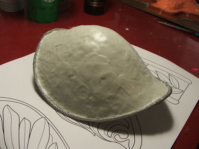
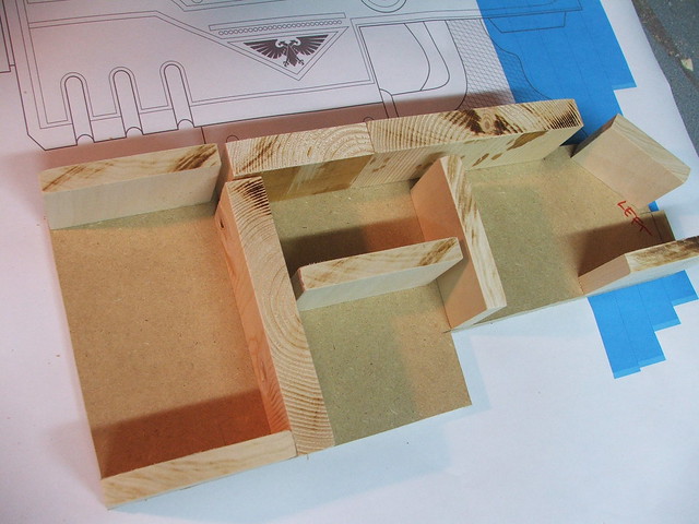
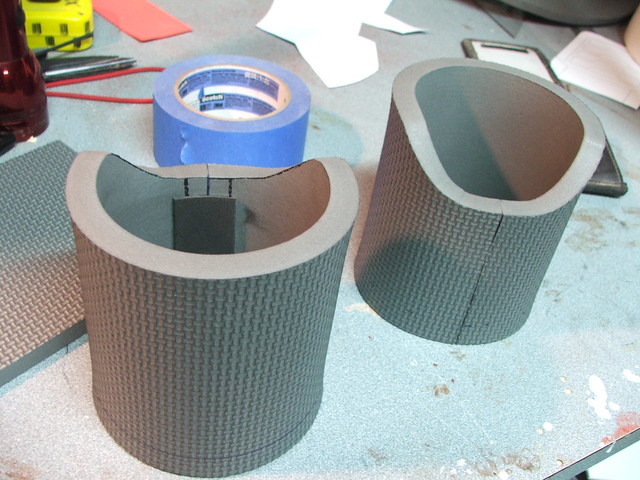
I started with 1/4″ MDF. The goal was to make this as light as possible, as it was going to be a convention piece and worn for a while. Layered rings of MDF were cut so the middle of the shield could be kept hollow.
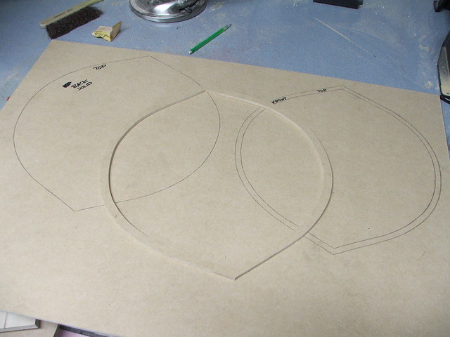
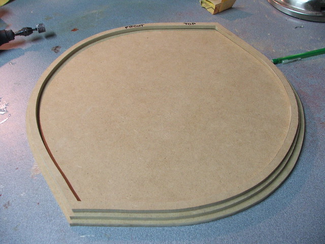
These were beveled on a table router, then clamped and glued into place.
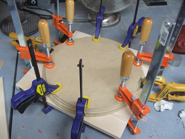
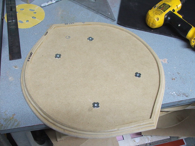
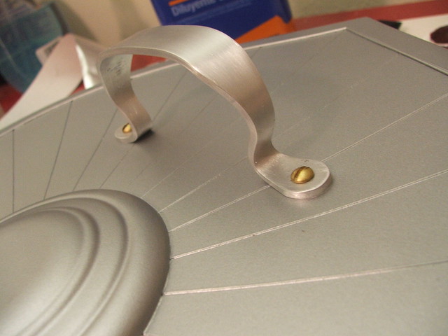
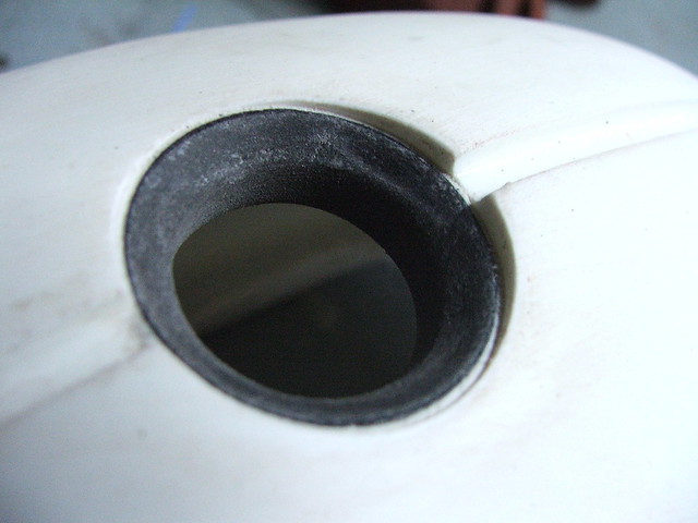
In anticipation of the straps and handle mounting, I added t-nuts to the backside of the shield, with their mounting brackets facing inwards.
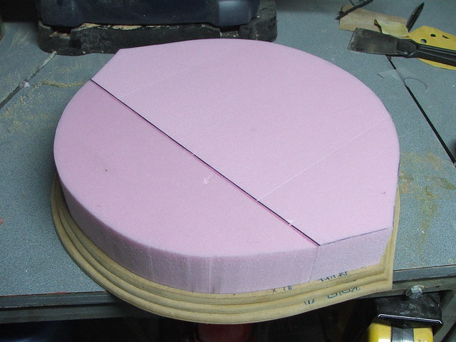
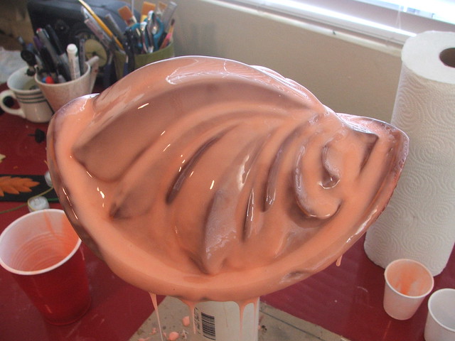
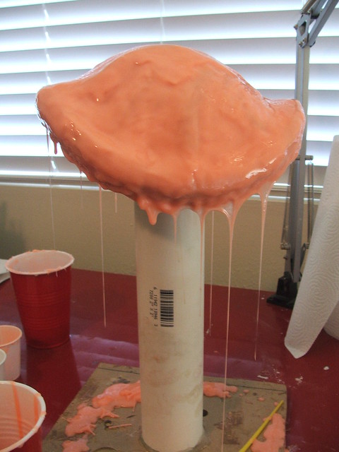
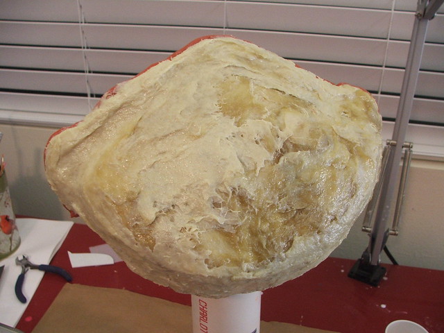
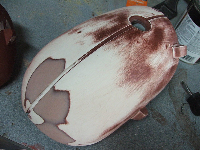
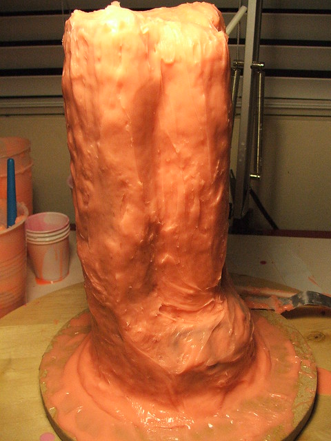
The cavity in the center of the shield was filled with foamcoare, then topped with 2″ insulation foam. I used gorilla glue to hold everything together. After it dried, the insulation foam was sanded into the “domed” shape of the shield front.

A lot of cosplayers struggle with the best way to seal foam. Extruded polystyrene foam is easily dissolved by polyester resins as well as the accelerants in most spraypaints. I have used a product called UreShell in the past, but ultimately I didn’t like the fact that it wasn’t sandable when dried and felt slightly rubbery. After doing some tests to make sure nothing would melt, I decided to coat the foam on the shield in urethane casting resin, specifically SmoothCast 300. Applied with a sponge brush, it dried to a strong and sandable outer layer without deforming the foam at all.
The resin has been tinted with red dye for this process, so it was easier to see where I’d brushed on layers.
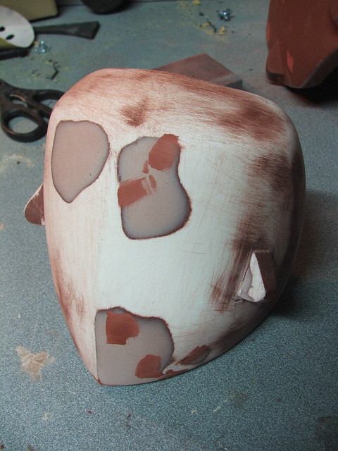
After this, I put down a coat of primer and began filling divots and pits with bondo.
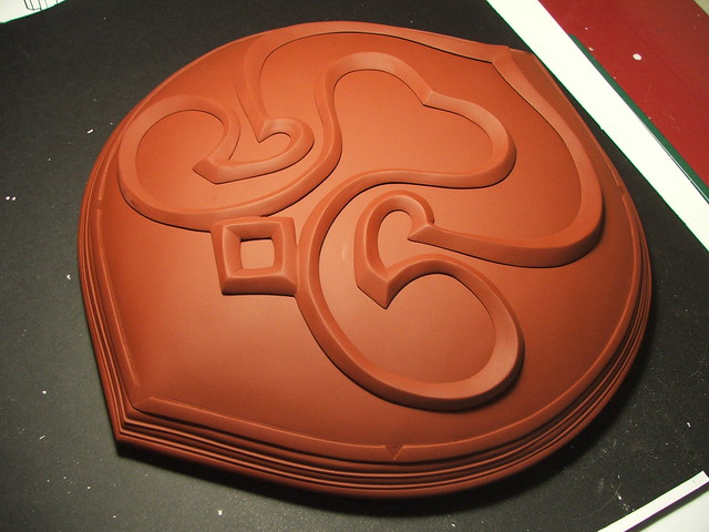
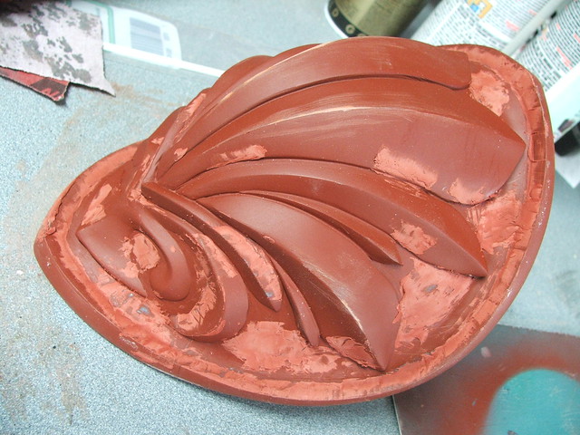
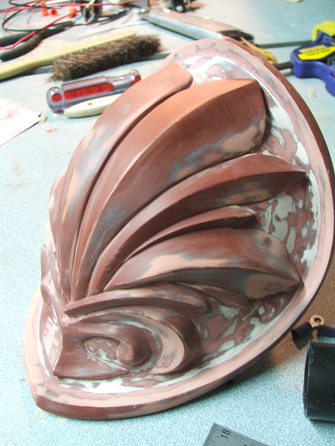
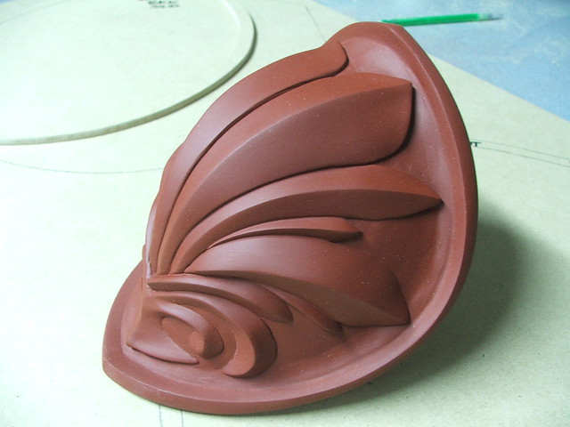
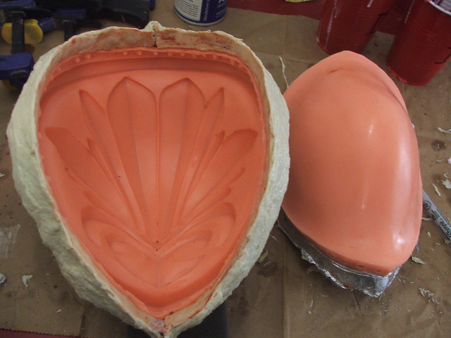
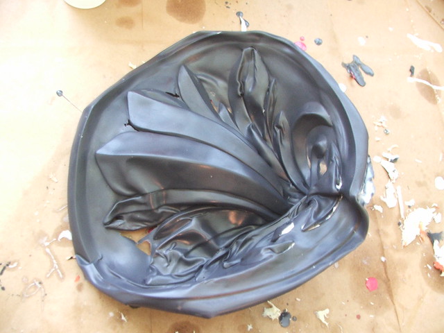
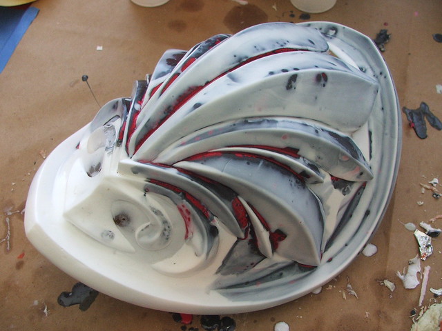
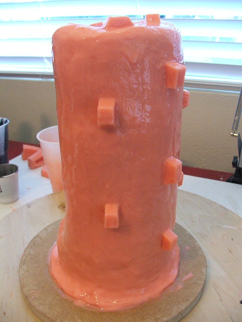
The raised filigree on the face of the shield was another interesting challenge. To do this, I printed out the filigree pattern on paper, then trimmed it to shape. The raised piece was then sculpted on top of the paper in Apoxie clay, using the edges as guides.
While the clay was still wet, I transferred the paper over to the face of the shield. The clay was heavy enough to weigh down and conform to the contour of the shield front, while the paper backing kept the clay from adhering to the shield itself.

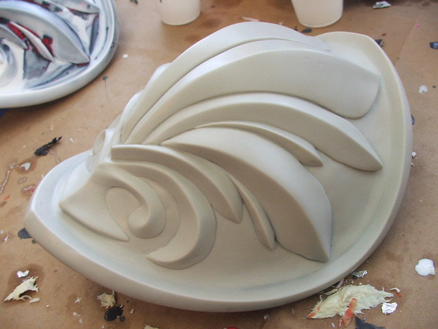
The benefit of this is that after the clay dried, I was able to remove the decorative element and sand the edges to a much smoother finish. This also made it possible for me to paint the pieces separately later on, making the finishing process much easier.
Continuing with the Apoxie sculpt, I added the raised detail edge to the side of the shield, and blended the corner bevels into one another with styrene parts and more clay.
Sculpting finished on the front!
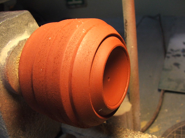
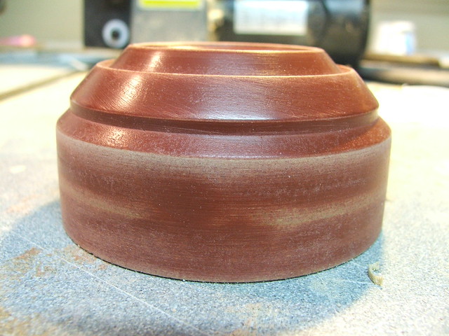
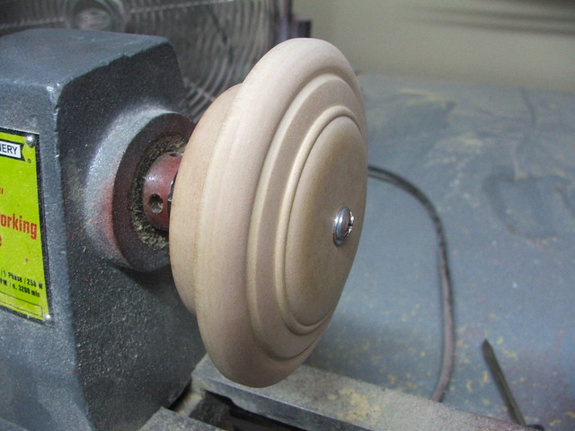
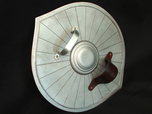
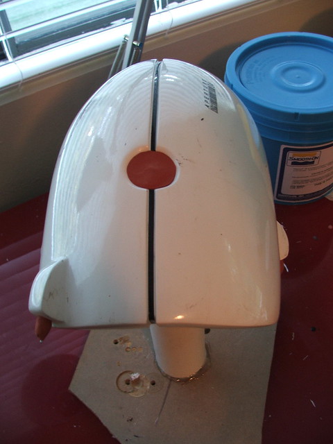
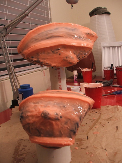
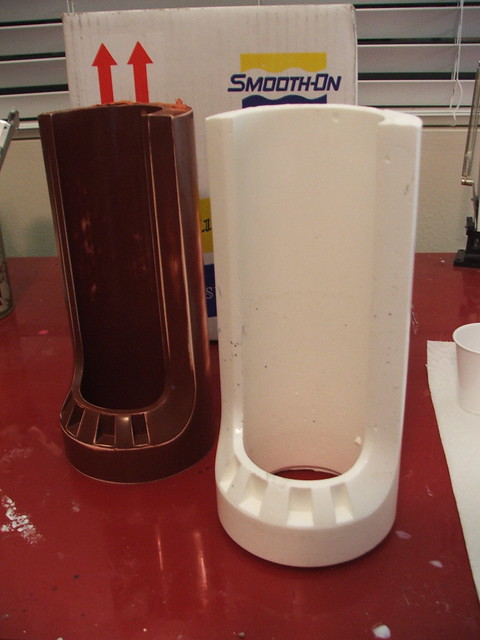
For the back of the shield, I started off lathing the back dome out of MDF, then vacuumformed it in .060″ styrene plastic.
The back panel of the shield was trimmed out of more styrene, and lines were scored in the surface with a lino block carving tool to simulate the individual sectioned plates.
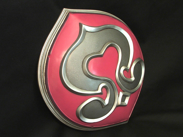
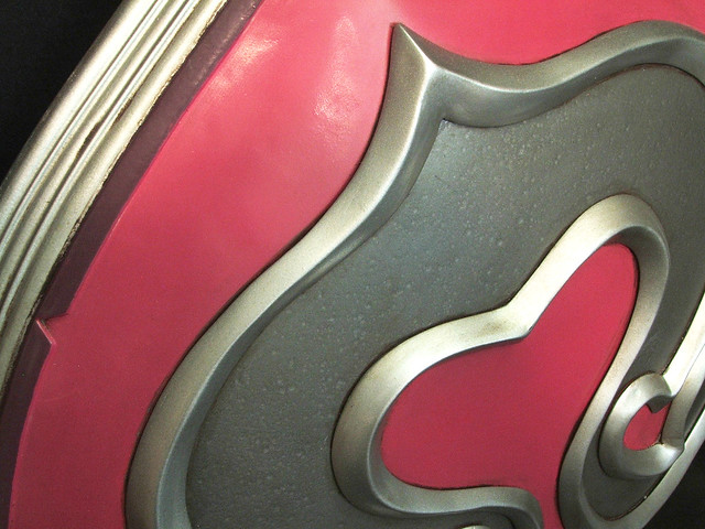
On to paint! The face of the shield was painted an alarmingly bright shade of fuchsia, then the area for the detail inset was masked off. This was then sprayed with hammered metal textured paint to give the surface a metallic look.

The filigree was painted separately, then epoxied in place after base coats had dried. Like I mentioned earlier, painting was much easier because of the modular build approach. Masking this thing off would have been a nightmare.
The edges of the shield as well as the back were finished with the same dull aluminum paint as the raised detail. I used Testors enamel to hand paint the purple trim.

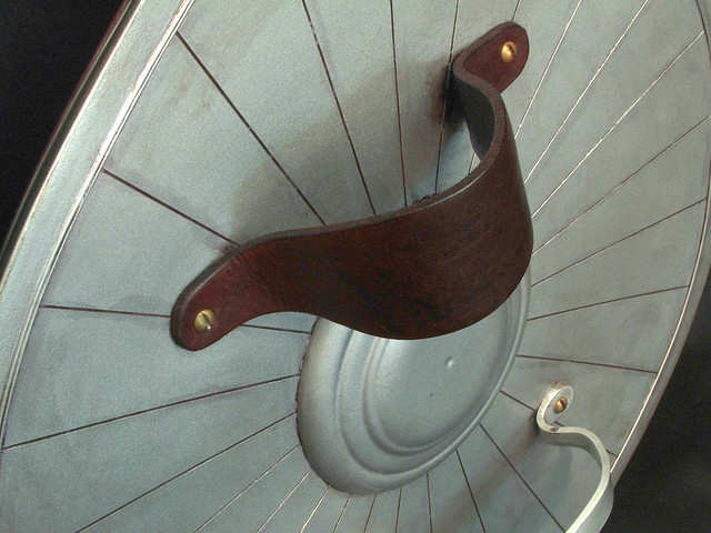
For the back, a handle was made using bar stock aluminum, trimmed and bent to shape. For the strap, I bought some leather hide and cured it over a round form to get the curved shape seen here.

The surface of the shield was lightly buffed with automotive wax before weathering to give it a dull sheen. After some light passes with the airbrush, here’s the finished product!
There’s one more installment on Cassandra’s equipment coming up – the Digamma sword. Look for this in the next few weeks, as its currently undergoing some minor restoration after taking a few hits at Dragon*Con
Higher resolution pics are available on my flickr page. As always, thanks for reading!

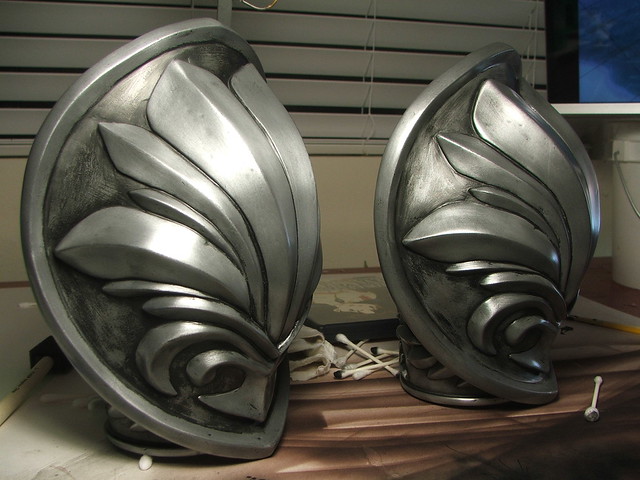
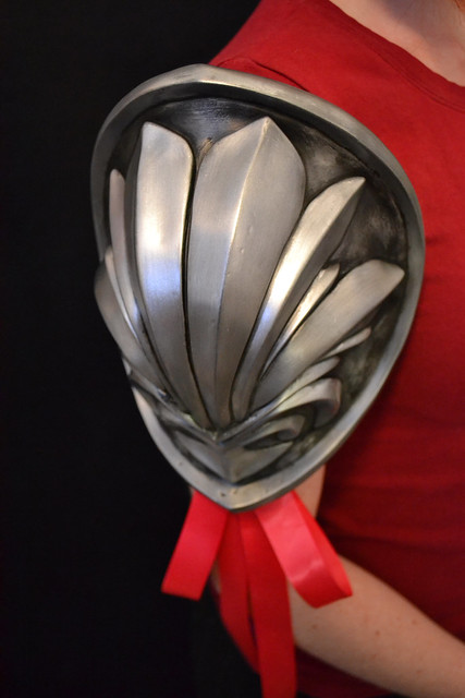
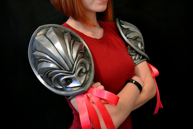
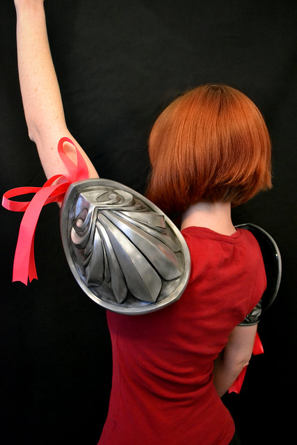
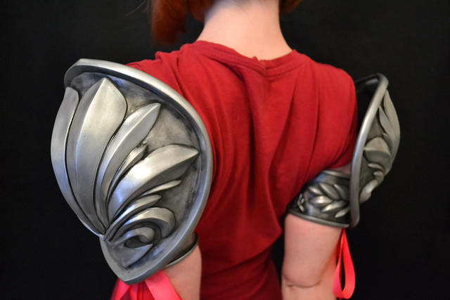
Cassandra’s Pauldrons
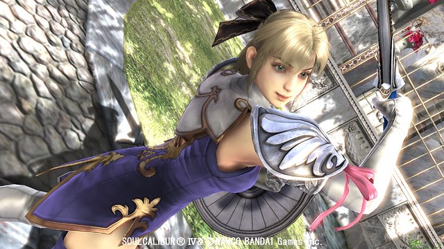
The SoulCalibur series has been one of my favorite gaming franchises for a long time. Since SC2, my go-to character has been Cassandra, as much for her fighting style as her snarky commentary and character design.
Don’t make excuses. A loss is a loss. – Cassandra
As a personal project of mine, I had decided at one point to make Cassandra’s sword & shield from the latest installment of the franchise, SoulCalibur IV. My wife mentioned “If you make the armor, then I’ll do the rest of the costume.”
And thats where we find ourselves now.
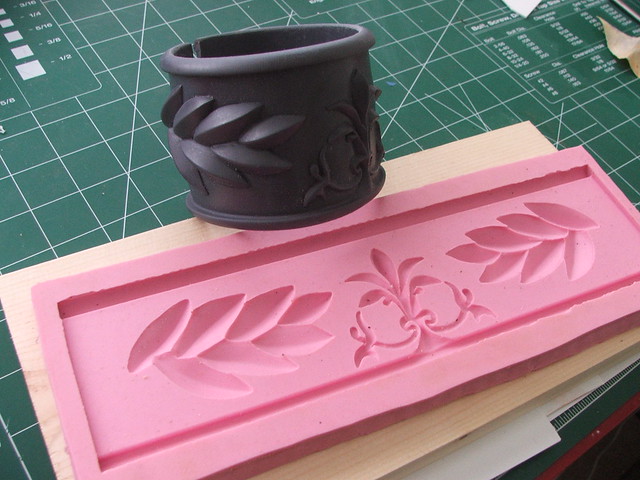
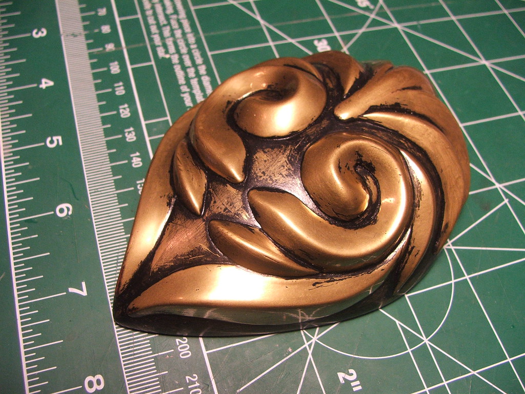
The “armor” amounted, really, to a pair of shoulder pauldrons. I liked the challenge of this project – it seems like lately all I’ve been making is guns, and the chance to do something organic and sculpted. It may not be the world’s best method, but I started out by making some 2D illustrated flats of the pauldron and arm cuff. Since they’re symmetrical front to back, making a single pauldron and molding it seemed like the best course of action.
Starting off, I made a base from sculpting armature wire and mesh.

This shape was skinned in a thin layer of apoxie sculpt to define the shape and give me a base to work over.
I wish I had a more scientific method of doing this, but from there I pretty much just eyeballed the blueprint drawings onto the surface of the form. after working with a dial caliper and ruler on my more “geometric” builds, this took some refining to get where I liked it.

More apoxie sculpt followed (and I was trying to use the very last of that awful tub of orange colored clay I had) to build up the shape of the filigree.
Since my sculpting skills are a C+ at best, there was a lot of sanding to be done after the clay had dried.
After shaping the feathery bits, the edge was also added in more apoxie sculpt. The whole thing was starting to get pretty weighty at this point, so its a good thing I decided to go with molded pieces for the final.

Sanding…
Spot Putty…
More sanding…
And some primer…
Then we’re ready for molding!
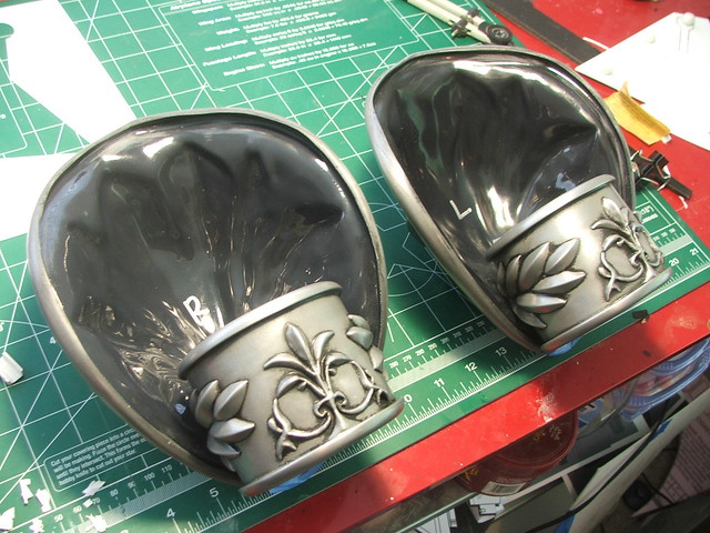
The arm cuff followed a similar process. I measured the circumference of Emily’s bicep to figure out how wide the base piece had to be to wrap around her arm. A piece of sintra served as a base to sculpt on top of, and the top parts were made with apoxie sculpt. Sparing you the details of sand/bondo/repeat, here’s the jist:

The pauldron molds were made with Rebound-25 silicone, while the arm cuff was done in Mold Max 30. The pauldron part was suspended on a PVC pipe for the brush coat first.
This was followed by thickened silicone, registration keys, and finally a jacket mold made from plasti-paste.
Originally, I had intended to make a front and back part to the piece, then join them and pour in resin to be slush cast. I was hoping this would make a nice, lightweight, hollow piece.
I was wrong. These were my first two attempts. I got better from the first to the second, but the piece is so thin that the resin wasn’t flowing completely to all parts of the inner cavity. The first piece wasn’t thick enough to hold its own shape, and the second one was so thin in some parts you could see through it.
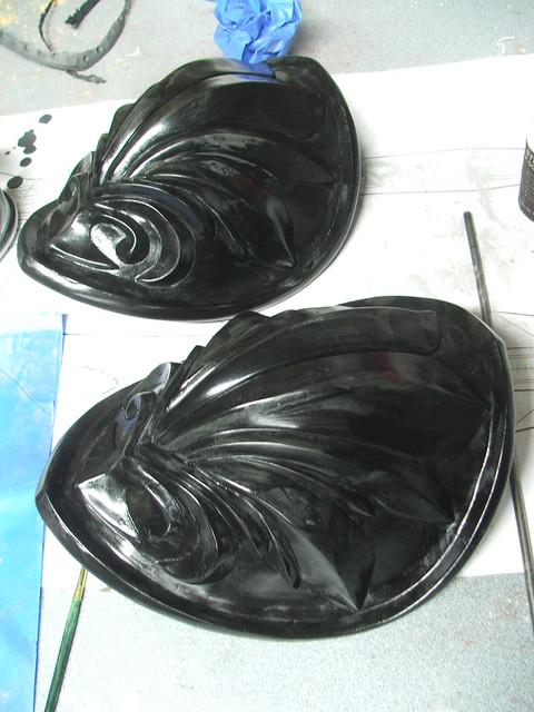
My third pass was done by removing the back part of the mold and slush casting the piece. MUCH better.
Progress?
With the practice out of the way, I started on the final pulls. The mold was dusted with aluminum powder first, then I slush cast the pieces in Smoothcast 300, dyed black.

Before I pull the cover on that though, you might have noticed that I sculpted the arm cuff as a flat bar. This might seem odd as most people’s arms aren’t two-dimensional, but sculpting something on a curved surface gave me a headache just thinking about it. I had an idea when making this part; a bit of a gamble, but it really paid off in the end.
The mold was first done over the flat sculpt. Before pouring the resin, I made sure the mold rubber was completely level and on a flat surface.
When pouring this piece, I used the same aluminum powder and black dye as before.
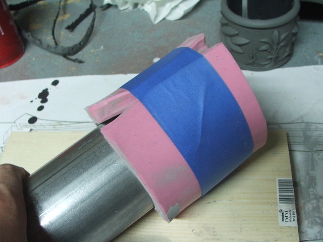
As resin cures, it starts to change color. At this point, its not 100% cured, but still rigid enough to maintain its shape. If you remove a pour from a mold too early, it can deform rather easily but still look similar to the desired shape. When the resin in the arm cuff mold started to change color, I picked up the rubber and wrapped it around a 3″ steel pipe.
After about 30 minutes, the resin was fully cured and I was able to remove the piece – now perfectly cylindrical!
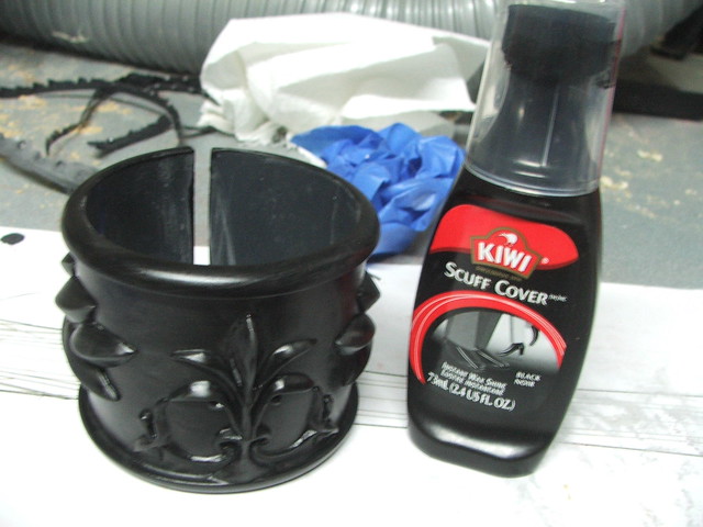
Here’s the two pieces together after buffing the aluminum coating lightly with some steel wool.
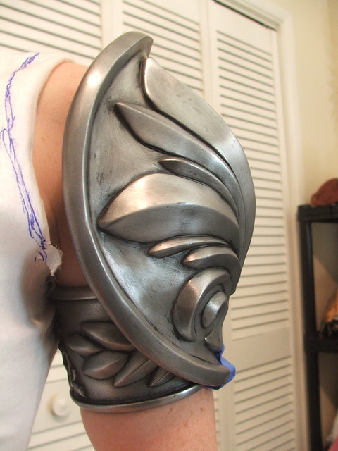
From here, I used shoe polish as a base coat of weathering.
This was buffed off the higher parts to leave the underside dirty. After that, an airbrush was used with layers of dark brown and black to further knock back the recessed areas.

Apoxie Sculpt was used to level out the inside area of the pauldron, and the cuffs were epoxied in place.
The finishing touch was a coat of rub-n-buff wax in “antique silver” and the *light red ribbons affixed to the middle of both pieces.
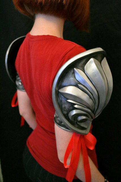
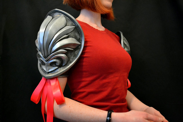
There are no straps that hold these in place. Each pauldron weighs just under 1lb, and since the arm cuffs are designed to be the same circumference as the wearer’s arm, they stay in place via friction with only a small strip of 1/4″ foam to take up any slack. They also do not affect the ability to move your arms in any direction, which is a LOT more than I can say for most videogame armor.

Posts detailing the build-up of Cassandra’s sword and shield to come, and more pics of the build process for these can be found on my flickr page – thanks for reading!

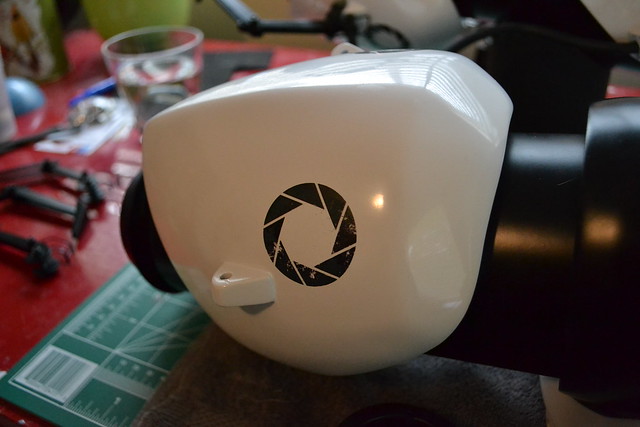
Portal Gun for Child’s Play
On January 20, 2009 I took a photograph of a project. At the beginning, the intent had been to get it done in time for Halloween 2008, but that deadline came and passed far too quickly for me to make it in time. Instead, the piece was quietly wrapped up over the holidays. Before going to bed one night, I tossed that picture and a few others up on Cosplay.com
The result has, quite literally, changed my life.
Anyone who has stumbled past my humble little blog here has no doubt heard of Penny Arcade. Linking to them from here is almost silly, like asking a fish if they’ve ever tried water before. Back in 2003, Penny Arcade founded a charity, run by gamers, called “Child’s Play” – a gaming industry charity dedicated to improving the lives of children with toys and games in a network of over 60 hospitals worldwide.
It’s hard not to be cheesy when you say something like this, but making these replicas has changed my life for the better, and I wanted to do the same for someone else. Ever since I finished my first Portal replica nearly 2 years ago, I had it in my head to make another specifically to benefit this cause. This particular replica will be auctioned off at the Child’s Play charity dinner in Seattle on December 7th. Along with it will be a custom base signed by the guys at Valve!
With that heaping pressure piled on, I really had to make sure this thing turned out good.
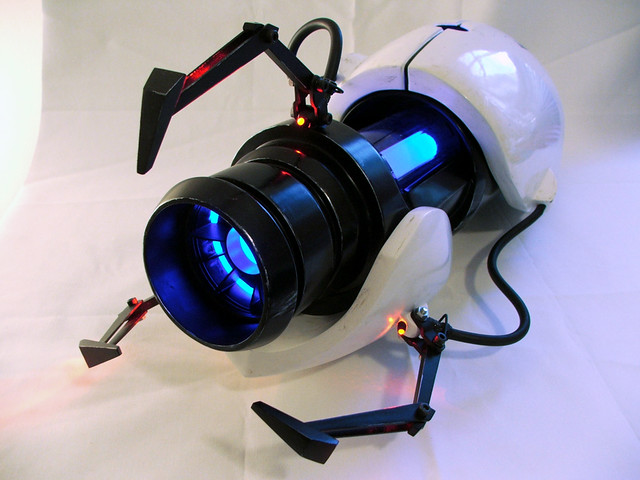
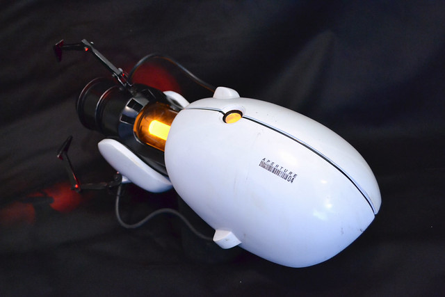
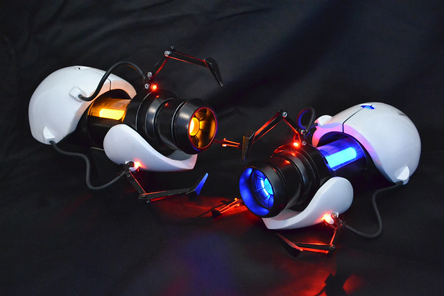
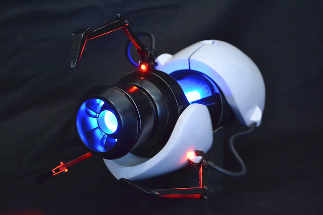 The final product!
What follows is a more involved build log of the process, now that I know what I’m doing a hell of a lot better than when I first took a stab at making the Portal Gun.
Initially, my aim was to duplicate as many parts of the original Portal Gun (we’ll call this “V1” for typing purposes) as possible. I popped off the front and rear casings and set about making a few molds.
These were made with brush-on Rebound 25 silicone, and the mold jackets were made using fiberglass.

After pouring in some smoothcast 300 resin, I had some very nice pulls. Only some minor cleanup was needed (which you’ll see more of, below)
While the whole project was blown apart, I molded some of the smaller detail pieces as well. These are the prongs and center barrel chamber plates from the original build.
At one point, I tried to mold the entire barrel of V1 so I could pull an whole assembly as a single piece. This, in retrospect, was one of the dumbest things I’ve ever tried to do prop-wise, and only succeeded in wasting 2 gallons of silicone, a week of my life, and severely damaging the barrel trying to extract it.

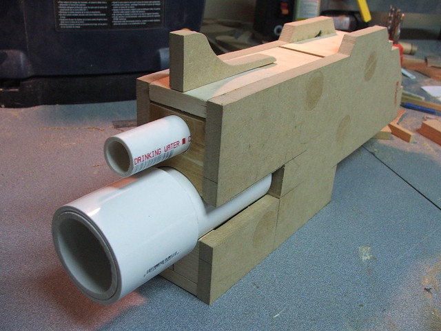
I had to try something new… Or, rather, try something old that I knew how to do a lot more precisely this time. Reaching back to the way V1 was constructed, I went to purchase some PVC pipe. 2 pieces were notched and set inside one another to create the “middle” section of the barrel.

One of the more annoying things encountered when making V1 was cutting the squared recesses into the front of the barrel. This time, I glued small styrene dams in place, sanding them down at an angle before filling the middle cavity.
The space between the PVC was then filled with apoxie sculpt and sanded flush.

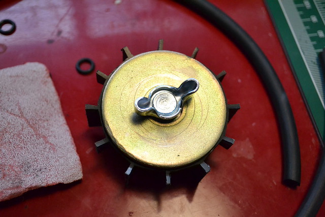
For the front most barrel section, I glued 7 discs of MDF together and settled in for some quality time with my lathe. This “plug” wasn’t made hollow; that would be a hurdle taken care of during the casting process.
A bit of primer and sanding later, toss on the raw pulls of the casings, and it was starting to take on a very familiar shape…

The casings weren’t perfect though, and needed some filler to even out a few flat spots.
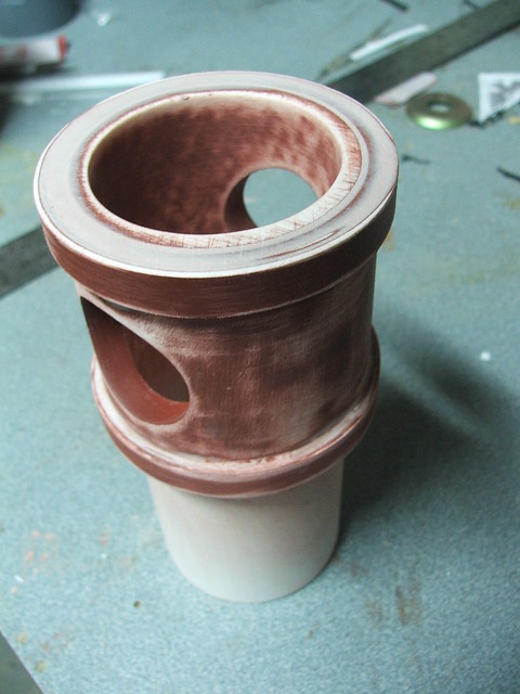
I also decided to make a more precise edge for the upper indicator light. On V1, this piece was made using a hand dremel tool. Now that I have a lathe, I wanted a true circular part with an even edge, so a new piece was made from sintra and epoxied into place.
The barrel pieces then went under the rubber to have some molds made. The central barrel was the trickiest, but thanks to the guys over at the Replica Prop Forum lending me some advice, I was able to get it figured out.

The front barrel was molded from the back side while the “front” was used as the pour area.

By pouring in a very small amount of resin, then inserting a 2.75″ diameter tube, I was able to create the hollow area in the middle of the barrel. After the small resin at the base cured, I poured in more around the surrounding edges, eventually making the entire hollow form. You can see the inserted tube in the shot below as a different color black than the resin surrounding it.

The rear-most section of the barrel was created, as before, with two 4″ PVC couplers epoxied together. I created a myriad of mounting points with T-nuts and sintra so the entire replica could be painted in sections and assembled later.
I started referring to this part of the build as the “chassis” since all of the electronic components will live here and it serves as the mounting point for all of the rest of the gun pieces.
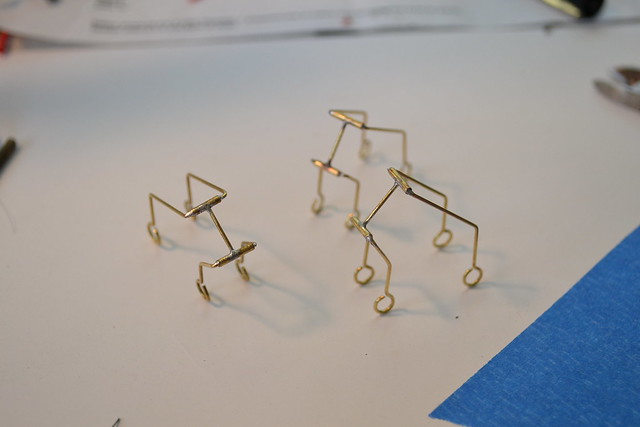
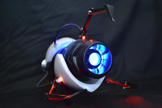
The claws were modified from V1 rather heavily. A reader on my blog (who happens to be building his own ASHPD as well) sent me some very high-resolution pics of the claws and their mounting areas. I used some components, and rebuilt others, to get the pieces below.

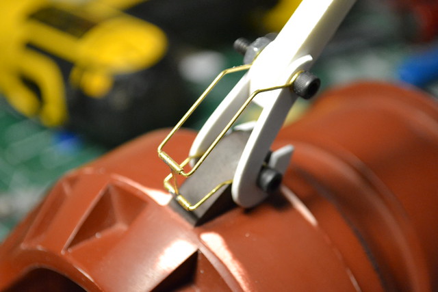
The biggest change in the claws were the wire “cages” that encase the hoses running the length of the gun exterior. These were built from brass wire and brazed together.
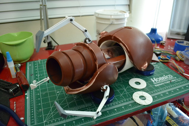
Quick test fit of all the components!
Before paint, I had to sort out electronics. This gun would light up as V1 did, but I wanted to include the sounds from the game as well. There would be a “boot up” noise when turning the gun on, individual firing noises for blue and orange portals, and a “fizzle” noise when turning it off. This gun is being created for a very special cause, so I wanted it to have some very special features.
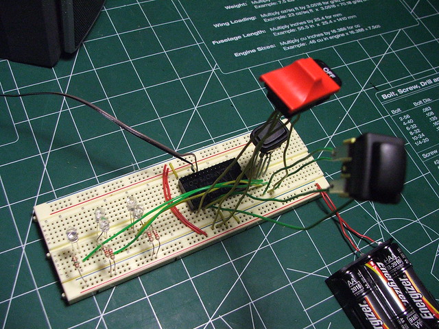
The LED board were made from simple perfboard and ribbon cable, using 5mm “piranha” style LEDs for illumination.
replicaprops.com handled the creation of the sound chip. All I had to do was provide .wav files and let them know how I wanted it triggered, and a week later I got my pre-programed chip & amp in the mail. Great guys to work with and very fast service. Below is a video of the first “proof-of-theory” test fire.
A 2.5″ speaker lives at the base of the central barrel. The cool thing about the gun design is that the long, continuous chamber provides rather fortunate acoustics, amplifying the volume of the sound effects really well and projecting them forwards.
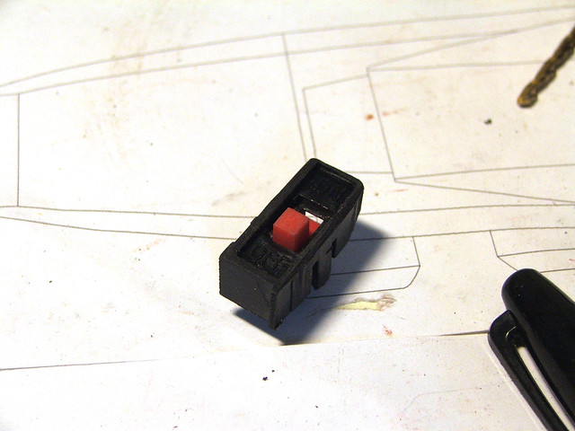
From the back of the gun, this switch plate controls the illumination and sound effects. The red switch on the right turns the gun on and off, while the two black switches on the left control which portal color is selected, and the sound effects for firing.

Now that the electronics were good to go, the rest of the parts got their paint topcoat.

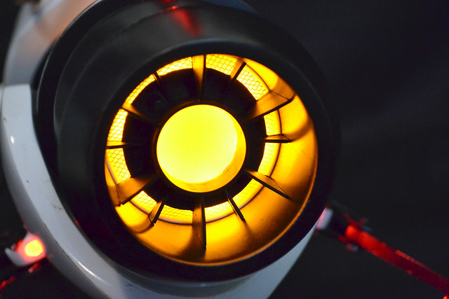
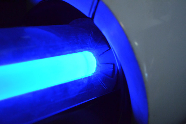
As with V1, an acrylic plunger handle was sourced to serve as the central illuminated chamber. 8 LEDs situated at the ends (4 of each color) keep the illumination clean and uniform. The piece was “frosted” for better light diffusion by buffing it with 600 grit sandpaper.

The revised upper indicator received a similar treatment. All of the LEDs were set into PVC sockets so they could easily be plugged into their acrylic rod parts.
Decals were, as before, made with water-slide decal paper printed from a laserjet printer. These work best over light colors. Weathering to the decals was done in photoshop – they’re actually printed to look used.

The rubber lines running the length of the side of the gun were made from automotive windshield washer tubing with sculpting armature wire inside to keep its bent shape.

A paper spindle provided the the barrel insert as a finishing touch. I had used one of these in V1 but the barrel on that gun is nearly .5″ wider. There was a lot of trimming involved to get this thing in there. For added texture, I used some thin gauge sculpting mesh as a “screen” behind the insert. Foam padding was used to diffuse the LEDs into a more even glow.

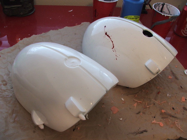
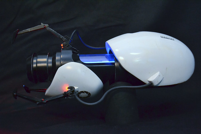
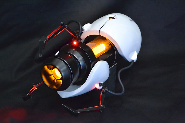
Illumination and first test-firing after final assembly!
V2 then got a very light coat of weathering, and I decided to not include the blood splatter from V1. This is a piece direct from the game, and as much as I love the narrative that detail gives my own personal ASHPD, I decided to keep this one “clean.”
I’ll need to update this post in about a week, as there is a custom base in the works as well. This will be signed by members of Valve (and me!) before the final gun goes on auction at the Child’s Play charity dinner, December 7th. I’ll be sure to post an update as soon as the auction is over and let everyone know how it went.
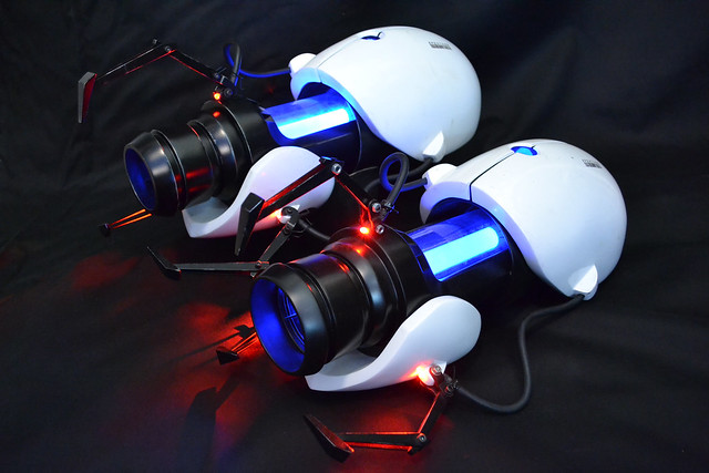
Some shots of the new Portal Gun, V2!
And a couple next to her twin. Hard to believe its almost been 2 years already. To everyone that subscribes, comments, follows along or even comes by the page, thanks for helping to build my little corner of the internet. You definitely motivate me to do great things.
More pictures available on my Flickr page. Thanks for reading!

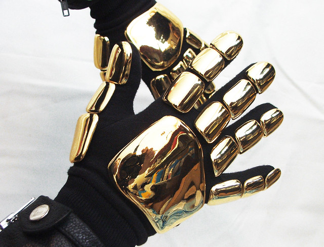
Daft Punk Handplates
It just makes sense, really. If you have the helmet then you’re going to need the gloves to go with it.

You might recall my vacuumformer build from a few months back. My reason for creating that tool was to eventually create a set of Daft Punk glove pieces. This all stemmed from a very helpful post over on the Replica Props Forum where a member had noted he had worked on a set of handplates for Daft Punk themselves while they were on tour! The originals, as it turns out, were vacuumformed. This information was perfect, and I set about creating a set of vac-forming masters.
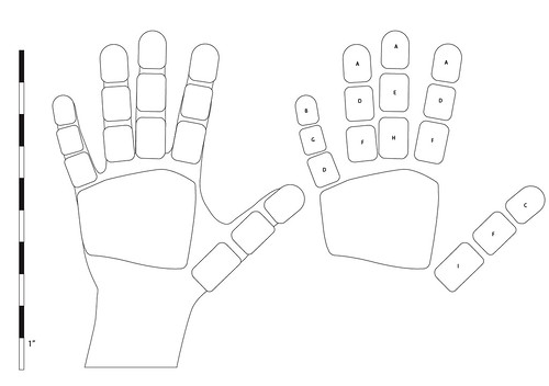
After a lot of research, I made up these blueprints to nail down the scale and shape of the plates.
First off, I got some alginate and cast a couple of copies of my hands. Alginate is great for single-use lifecasting and I had 2 exact copies of my paws in a couple hours. The finals were made with Smooth Cast 300 resin.
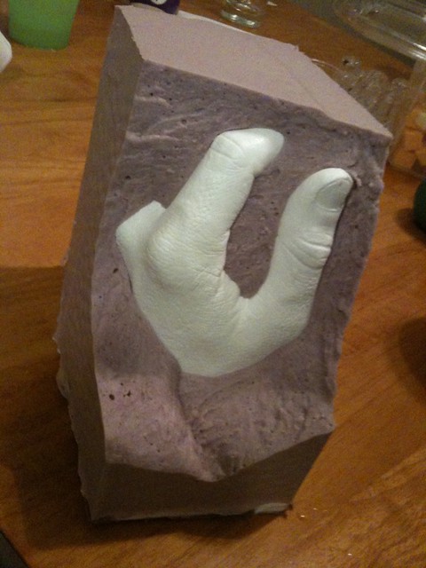
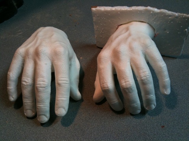
Once these were fully cured, I sculpted the hand plates over the finger sections with Apoxie Sculpt.
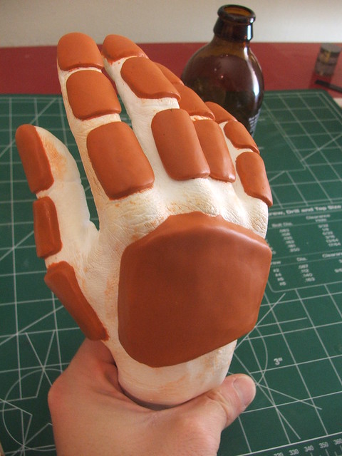
I only sculpted the finger plates on one hand, as they would be used for both fingers on both hands. The only parts that needed to be sculpted separately were the large back plates.
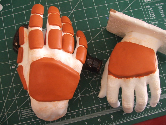
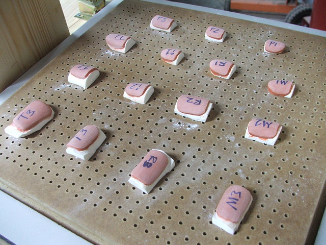
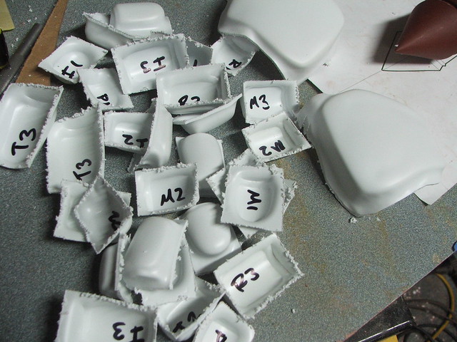
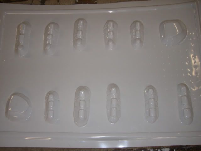
The next step was a bit unnerving. In order to use these pieces as vacuumform masters, they needed to be separated and the bottoms sanded flat. In order to do this, I cut each of the fingers off the palm on my bandsaw, then cut the fingers into individual sections.

These little hotdog slices all ended up looking very similar, so they were labeled to keep everything straight. The handplates, noticably different, were labeled as well. I get confused easily.

The first set of pulls went near flawlessly. These were done in .060″ styrene plastic.

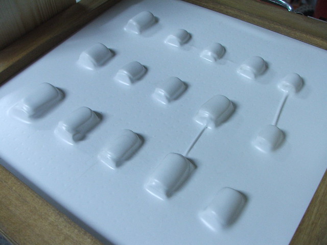
After removing the masters from the pull, I labeled the inside of the plates and cut them out roughly on my bandsaw.
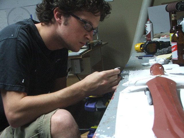
My preferred, or at least “settled-upon” method of trimming the edges to shape was to clamp my dremel tool to my workbench and shape each piece individually with a sanding drum. It took a while (4 hours!) but the results were worth it.
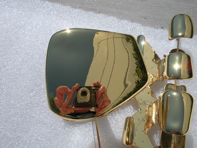
The result – all pieces trimmed, the edges smoothed with 1000 grit paper, and ready for chrome!
In order to set these up for spray chrome, I made a few parts trees (similar to model car kits) out of my scrap styrene. The plates were glued to the trees with a small dab of superglue, which would make them easy to snap off later after paint.

First photos from my friends over at Creations n’ Chrome. Beautiful!

Unfortunately, I don’t have a photo available for the “mounting” part. I ended up cutting small pieces of craft foam to fit into the recessed cavities of the concave glove plates. These were superglued to the styrene side. To affix them to the gloves, I used 3M black weatherstrip adhesive. Highly toxic and difficult to work with, but once it sets, the pieces are on there for life!
Note: I glued these in place using a friend of mine (Thanks, Dr. Roundtree!) as a stand-in hand mannequin. If you decide to do the same, have your hand model wear a set of latex gloves underneath the cloth ones. You do NOT want to glue this stuff to your skin.
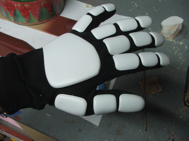
For gloves, I went to a camping store and bought some thin black glove liners. These have no markings and are lightweight as well, so nothing would get in the way of the design.

Some final shots of the pieces, all shiny and ready for Halloween!


Thanks for reading!


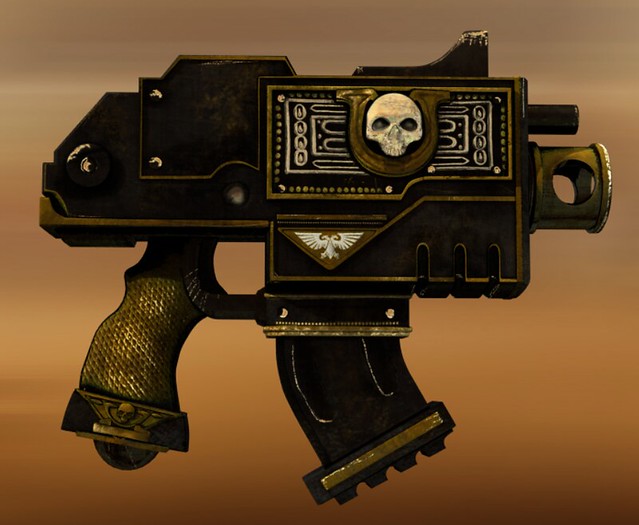
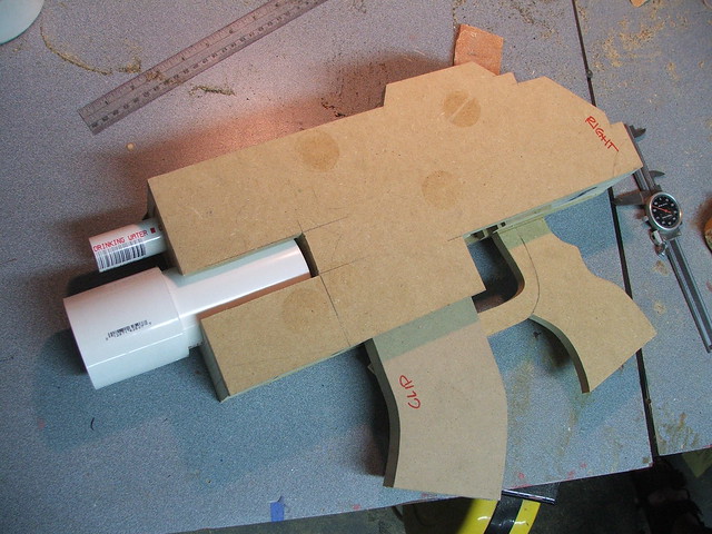
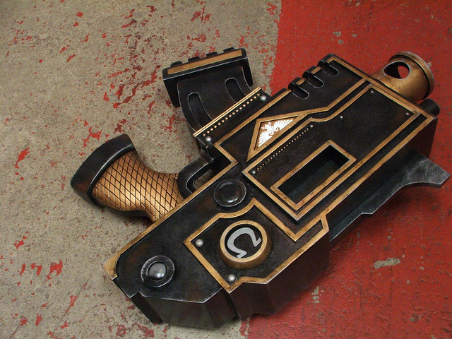
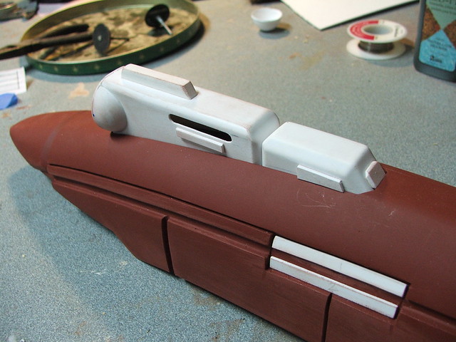
Ultramarines Bolt Pistol – Warhammer 40k
I got an email a couple of weeks ago, followed by a phone call. You’ll forgive me if the exact details are a bit fuzzy, but the conversation involved an inquiry into getting a replica bolt pistol from the upcoming movie Ultramarines, based in the Warhammer 40k universe. It went something like…
Them: “Any interest in creating some Warhammer 40k replicas? We’d need them by New York Comic Con.”
Me: “Sure! I’d love to – always liked the style of 40k. When is NYCC?”
Them: “In about 2 weeks. We’d need it a fair bit sooner than that.”
Me: “…oh”
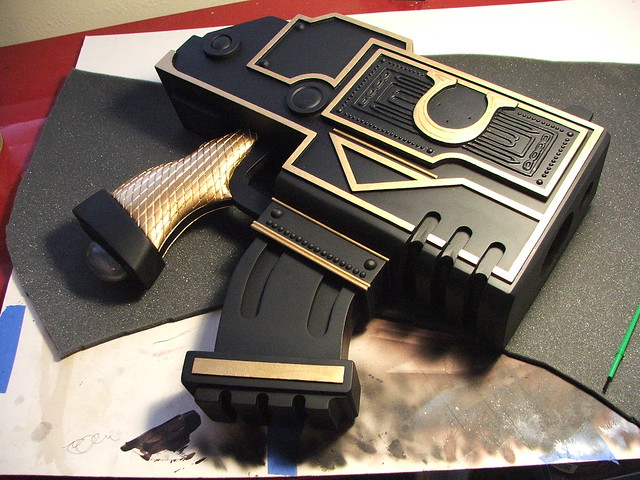
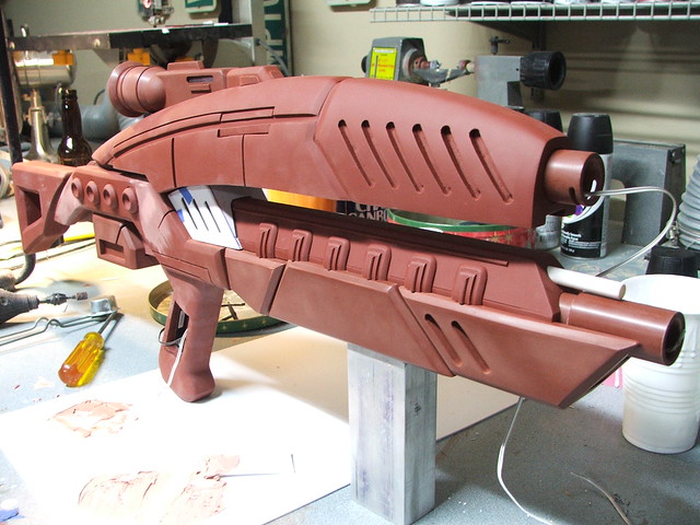
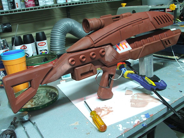
And so I found myself looking (figuratively, for the time being) down the barrel of a 9-day Warhammer pistol build. This project is to be a featured item at the Ultramarines booth at NYCC, and will also be handled by hundreds of convention attendees as they pose for pictures with it. It needed to be strong, durable, huge, and built in less than a week and a half. Here’s the nuts and bolts.
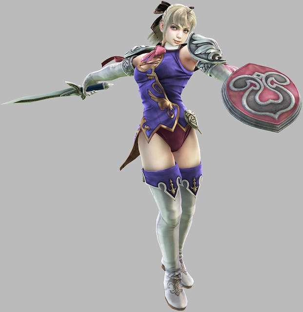
Here’s what we’re after; specifically, this Bolt Pistol belongs to the character Severus in the Ultramarines universe.
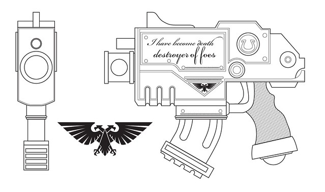
I started, as most long time readers are familiar with, by setting up some Illustrator blueprints. The exact details of the gun were still in discussion at this time and eventually the script lettering was abandoned in favor of a shell eject port.
As I continued with the project, I decided to take “closing shots” of my day-to-day progress. Anyone who wants the short, short version can check the following 9 photos:
 Day 2
Day 2 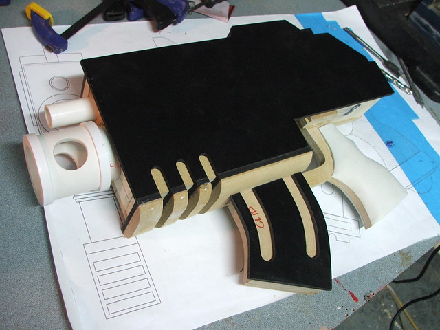 Day 3
Day 3 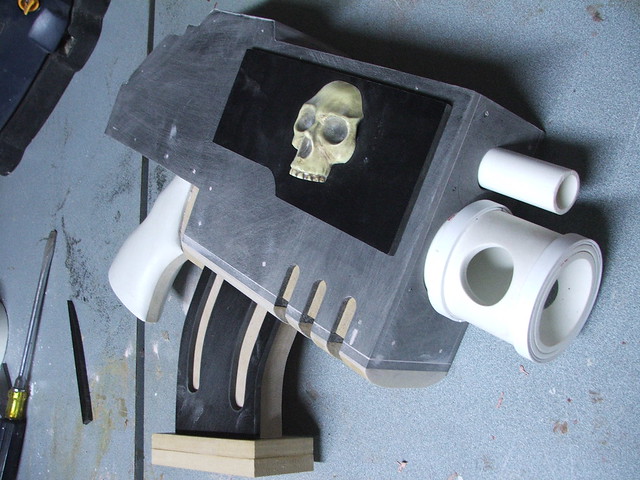 Day 4
Day 4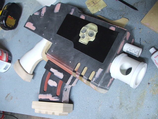 Day 5
Day 5 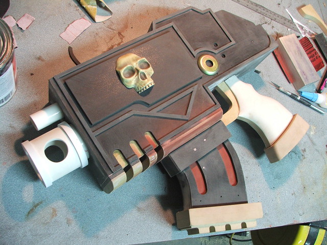 Day 6
Day 6 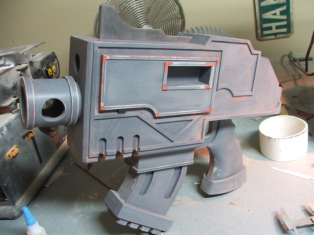 Day 7
Day 7 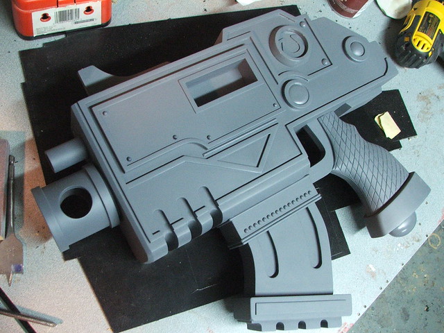 Day 8
Day 8  Day 9
Day 9 
The idea here was to make an ultra-rigid (ha! Ultra! Get it?!… ok, nevermind) frame from MDF. This would form the skeleton of the pistol, and the details would stem from this inner structure.
The basic components were transferred to MDF and trimmed on the bandsaw.
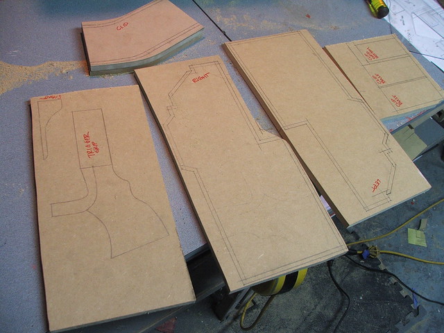
Inner panels were cut to create “chambers” on the inside of the pistol. These served a double purpose of adding rigidity while also creating mounting brackets for the grip, clip, and barrels.
Barrels started life as lowly PVC pipe. I have never purchased even a single inch of plumbing hardware that was used for its original intent.
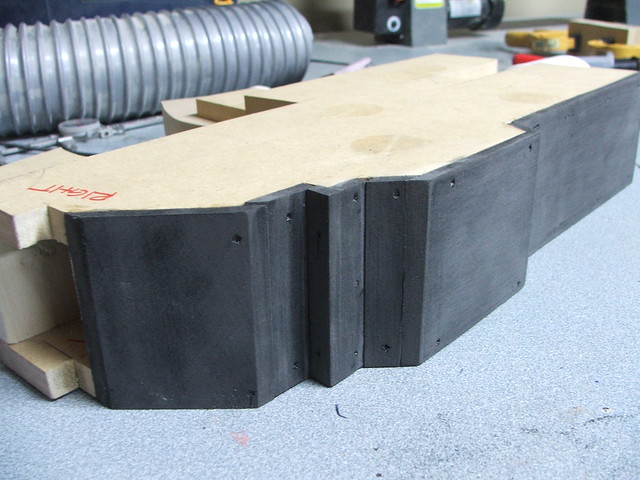
After the frame was complete, the structure was skinned in 1/4″ black sintra. These panels were coated in epoxy on their MDF facing side, then secured in place with a brad nailgun.

Additional panels being fitted to the rear of the gun
The raised lip on the barrel was added using styrene sheet. The seams were filled with bondo and sanded flush.

Another favorite of mine – Apoxie Sculpt – was used to create the handle shape. This was rough sculpted, then sanded to shape after drying.


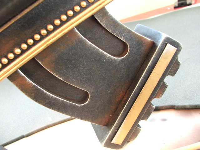
For the curved lower part of the gun, I shaped a piece of 1/2″ MDF on the belt sander, then sectioned it into thin strips to create the “cutouts” below the barrel.

Additional sintra sheet was added to the clip and clip receiver to build out those shapes to their proper dimension. Before adding the side details on the clip, I primed and sanded the MDF beneath it to save myself some very annoying detail sanding later.

Lower clip and grip details were created from sheets of MDF laminated together. The clip underside was shaped, rather frighteningly, on my table router.

Those were the last of the big details, so I started working on accent pieces and trim. The raised edges all around the perimeter of the gun were made from 1/8″ thick sintra, hand cut to 1/4″ wide.
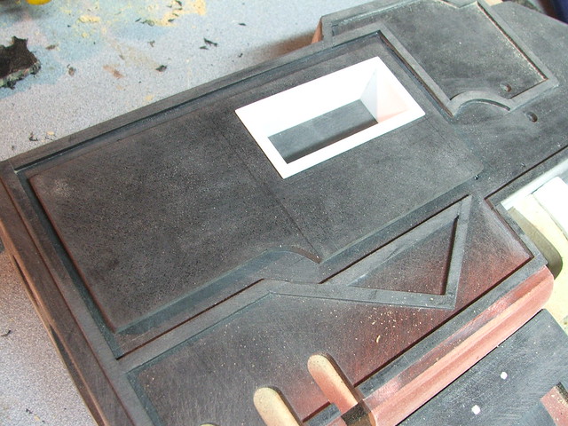
It was at this point that the shell casing eject port was determined to be the detail needed for the left side of the pistol. I didn’t want to risk raking my jigsaw across the side of the piece, so I “cut” the piece out with a series of .5″ drilled holes.
Not the prettiest solution, but I had a plate to cover up the hacked up gouges.
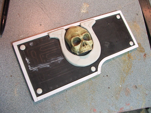
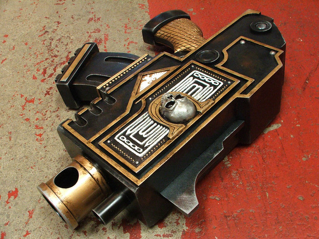
The right side of the pistol features a large “U” surrounded by rough sculpted filigree and containing the front half of a tiny human skull, sans jaw. I seriously lucked out getting this project so close to Halloween, and the skull was purchased from a local craft store and modified to fit the panel. The raised edges were added with apoxie sculpt.
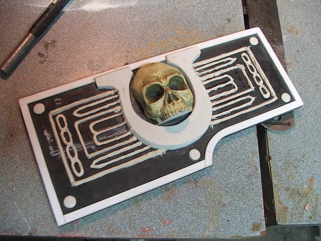
Additional details were added in styrene bar, then it was off to the first guide coat of primer.
This revealed a lot of cracks that still had yet to be filled by my first bondo passes, but also showed that I had a lot more details to add. The large side rivets were made by lathing pieces of 3/8″ sintra to shape.
3/8″ sintra also makes up the sight on the pistol… which I can only imagine leaves something to be desired with regard to accuracy.

The small rivets and domed details on other parts of the gun are actually half-spheres meant for scrapbooking. I peeled off the weak adhesive supplied by the manufacturer and epoxied them into place. For the really tiny ones, this was an eye straining process.
Speaking of strain, my wrist was killing me after carving the diamond details on both sides of the grip with an engraving tool. A smarter man would have made these marks while the clay was still wet. Alas, I am not that man.

The last big piece needed was the large “U” on the left side of the gun, aft of the shell eject port. This was a lathed piece of 3/8″ sintra, while the inset “U” was cut from .060 styrene sheet.
One more coat of primer…
…then its off to paint!
I started with a full coat of flat black; this was an idea I’d had for creating a more accurate “gunmetal” color for a while now and was eager to test out. Retrospectively, trying new things with 2 days left on the clock wasn’t the brightest of moves… but nothing ventured, nothing gained.

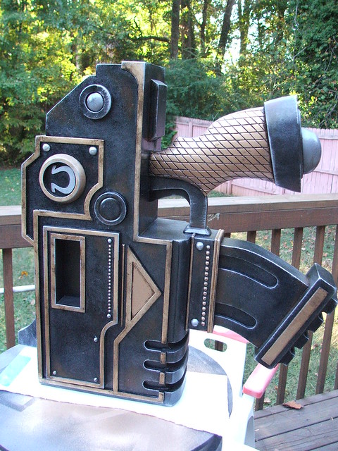
The barrel and shell got a coat of Krylon metallic gold. The shell was an insert I’d created last minute when I realized that it would be quite easy to see all the way down into the barrel, given its shallow depth and wide opening. May as well see the next round in the chamber!
After the flat black dried, the raised edges and grip were treated to a coat of gold as well. Krylon spray for the grip and Testor’s brush enamel for the trim. The two colors are remarkably (and luckily!) nearly identical.
Additional pieces, like the skull, some rivets, and the raised filigree, were painted with dull aluminum and white enamels.
The technique I spoke about earlier for achieving a better gunmetal color was gleaned from a papercraft Hellboy “Samaritan” pistol I stumbled upon several months back. (fantastic read for anyone interested in making one of those things!) Since I only needed a light metal shimmer to my black basecoat, I only did one very thin pass of stippling with some metallic dark silver acrylics.

Additional dirt and grit was added with further layers of acrylic paints drybrushed onto the surface.
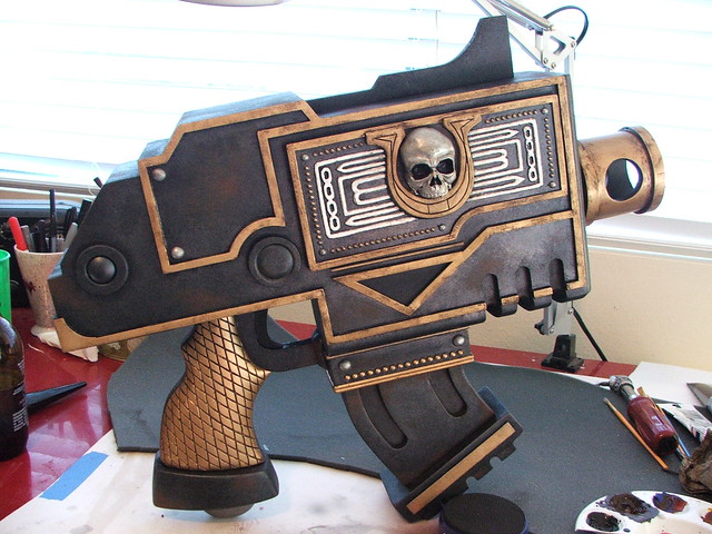
The final weathering accent was a light helping of silver “wear” marks around raised edges and corners, done with Testor’s dull aluminum enamel.

Once all of the above was dry, the entire gun got two coats of satin clearcoat to protect the weathering from the dozens of handlers it would have in the following week.
Glue in the barrels, and she’s done!
For scale reference, here’s my friend Tom holding the “pistol.” It weighs close to 17lbs and is nearly 2 feet long.
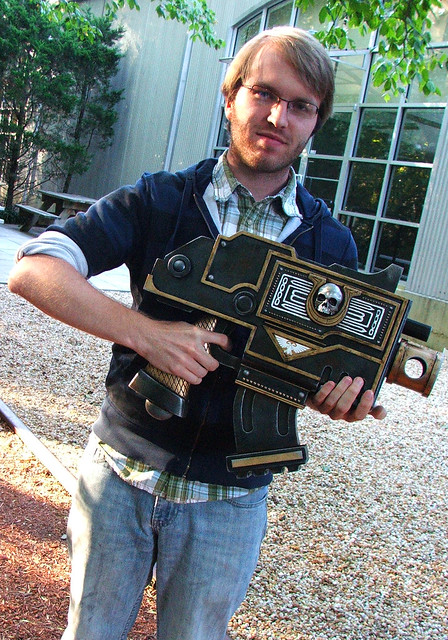
From first cut on the bandsaw to dropping it in the case, 9 days total. This was one hell of a rush build, and I really wish I could have had a month with it, but it turned out great in the end. If you’re going to NYCC this year, be sure to stop by the Ultramarines booth and have a pic taken with tiny here. I’d love to see it!


More pics of the process and final build (And in higher resolution) available on my flickr page.

As always, thanks for reading!

N7 Armor & Dragon*Con 2010 Recap
Alternate title: How to make your very own Foamshep.
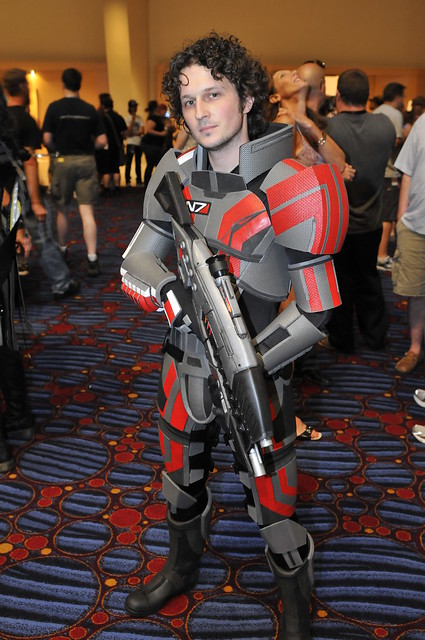
So, Dragon*Con 2010 (shameless link to an awesome recap video by my friends over at JumpKickPunch.com) loomed in the horizon and I had found myself without a costume. Long time readers may recall that last year I put together a Big Daddy costume from Bioshock, setting my own bar impossibly high for a repeat performance. The bulk of my time over the past several months has actually been invested in props for my wife’s costume, while my own remained mostly undecided.
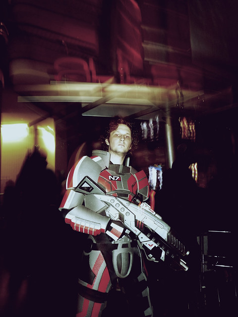
It was then that I ran across EvilFX’s “Bioweapons” blog. David does some truly amazing work, and his material choices are innovative and perfect for their application. He was putting together 2 sets of N7 armor for himself and his girlfriend, to be debuted at Dragon*Con 2010. I had 16 days and an M8 rifle, so I decided to try it for myself.
Now, this entry is a bit sparse for a couple of reasons. #1, this is not my technique – if you want to know more about it, I highly suggest visiting the EvilFX blog and reading through some of the entries. #2, in a time crunch, my project detailing is not nearly as thorough as it should be.
I’ll share a few tips that I ran across on my build for those interested in taking a whack at this themselves.
(original here – I did some touchup and erased the random con-goers from the background of the shot)
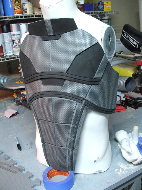
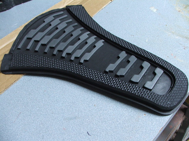
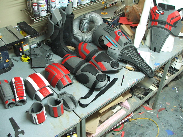
This material is called “EVA Foam” and can be purchased from industrial supply houses like McMaster-Carr. You’ve likely seen it used on Yoga mats and cheap flip-flops. Its durable, cheap, and comes in tons of fun colors. For this project, I used interlocking floor mats found on eBay, because their textured side simulates the “carbon fiber” look of the N7 armor fairly well. I wouldn’t have time to paint the entire suit, so I ordered gray.
As with most of my builds, I did toss together a quick set of blueprints. These weren’t nearly as detailed as I usually make, and only included the chest and back pieces.

The remainder of the pieces were patterned on the fly, from looking at multiple screenshots and my very best guesswork. I bought thin sheets of craft foam to make my patterns with, as these are also EVA and behave similarly to the thicker sheets.
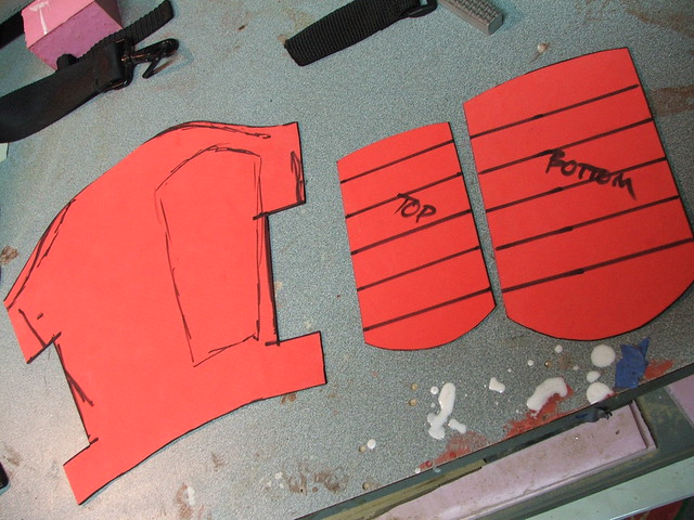
The patterns had to be increased along the circumference of their bend by about 5-10% in order to keep the same curve as the thinner templates. This took some getting used to, but after a couple pieces it started making more sense. The arm bracer here was my first complete piece.
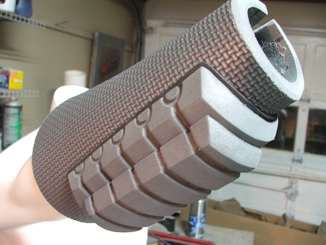
The thinner craft foam also worked very well for inset textures. Instead of trying to sand down an interior face completely smooth, I just carved it rough to shape with my dremel, then cut a piece to fit out of some 6mm craft foam. Crisp, even faces.

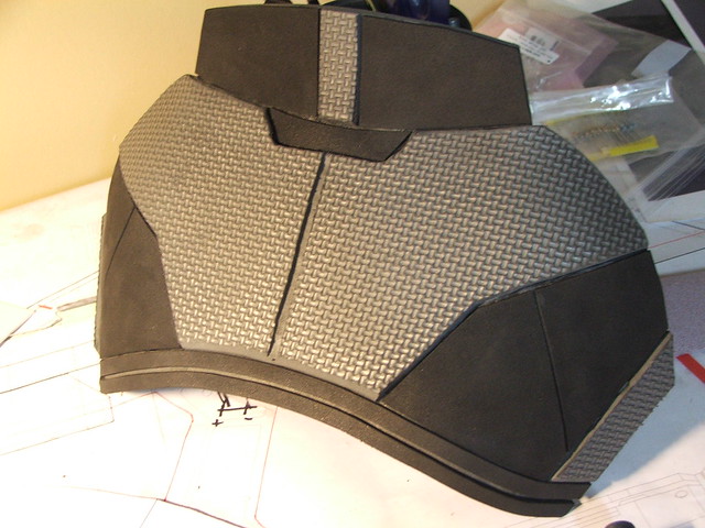
The “panel lines” in the armor were made by first using a hot knife to trace a line across the armor using a metal straight edge. After this, I retraced the line with a dremel tool, using a grinding wheel.
I was lucky enough to trade some lathe work with a friend of mine who laser-cut some of the more intricate spine and back details for me. Little bits like this would have driven me mad.
If you don’t typically have access to a laser cutter (as I know I usually don’t!) then I recommend a bandsaw. Most of my foam was trimmed using a medium wood blade on a 9″ bandsaw with no problems at all. Thinner pieces can get pulled into the blade and down into the wheels though, so be careful. I never used a hotknife for cutting, though I know others have.
Rigging these pieces was a fun challenge. The bicep pieces (below, little more than foam rings, really) and gauntlets stayed in place by friction alone, but the shoulders, thighs, and chest/back took some thought.
The chest/back was held on with 4 velcro straps (2 on each side) and 2 nylon clips that went up over the shoulders.
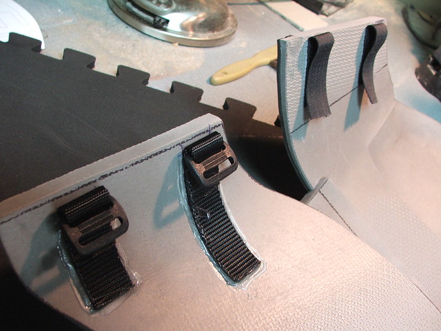
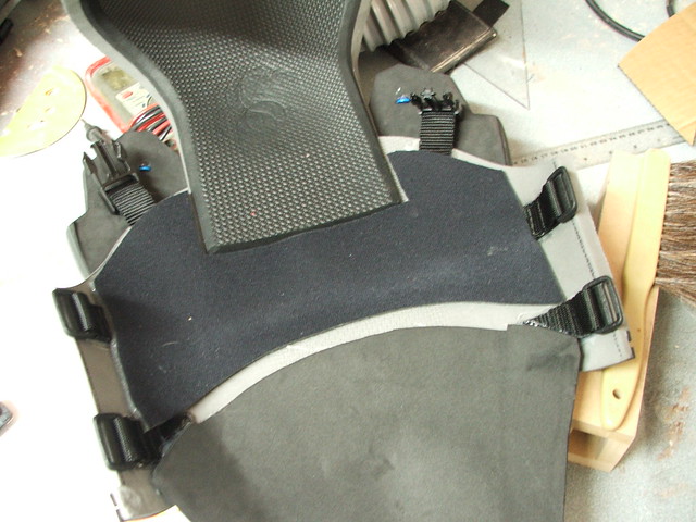
The over-the-shoulder straps threaded through the loops on the inside of the inner shoulder piece, holding then in place. The larger piece is connected to this with a strip of elastic, and another inner piece of elastic keeps the armor in place around the bicep.
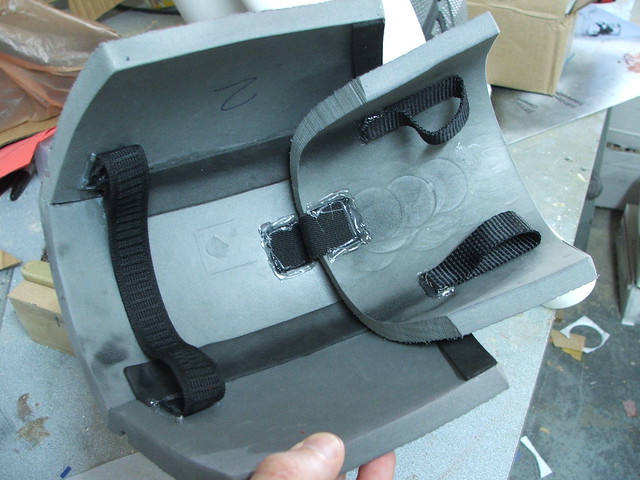
The thighs had three buckled straps a piece on the inside which somewhat held them in place, but luckily the guys at BioWare thought about them slipping down and gave us an out! There are two hip pucks that have a webbed nylon strap running through them, which attach to the chest and back pieces to keep them from sliding down.
I chucked up a piece of MDF on my lathe and popped out a quick master for some vacuumform pulls. These pieces were slotted to receive the webbing that holds the thigh piece up.
The thighs themselves were the result of a lot of heatgun and dremel work. If you’re looking to get these pieces in a compound curve, its best to heat them from both sides with a heatgun and pull them over a domed surface. I had some spare PVC endcaps for some 2″ pipe that worked really well for this. I also used my knee from time to time if the foam was cool enough.
Most of the shots above show hotglue holding the straps in, but that was the only place where hotglue was used. The foam itself was usually bonded together using superglue. I prefer the Gorilla Glue brand. These pieces held up for 2 days of use at DragonCon and none of the superglue ever let go. It can be a bit pricey though, as I went through 6 bottles for the entire suit.

The best tip I can give when working with this stuff is my painting technique. Since the surface is heavily textured and tape doesn’t adhere to it well, I had to find a way to mask off the plethora of stripes I had planned to add to the suit. For this, I first laid out the pattern in tin ducting tape.
By tracing the edges of the tape with an exacto knife, you create a small indent in the foam. Using a brush, you can paint up to this line to create a clean edge. Its tedious and does take a significant amount of time (the stripes on my suit took me about 7 hours) but the results were worth it.

I had the same vinyl shop that did the decals on the M8 (Signs Now) put together some N7 vinyl decals for me to use on the chest plate. I used a piece of black sintra, heated and bent to shape, for the backing. You can see the red paint cracked pretty bad after the con in the shot below – the red used was laquer and the white was enamel. It seems like the enamel holds better to the foam.

Lastly, I added some blue EL wire to the back, running off 2 AA batteries. This was my first time using the stuff, and aside from that annoying high-pitched tone the inverter gives off, its a very cool lighting tool. Remember, if you can make something glow, its instantly cooler!
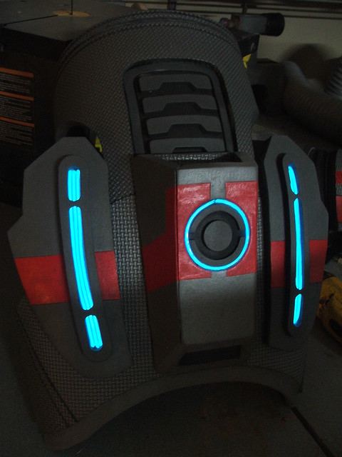
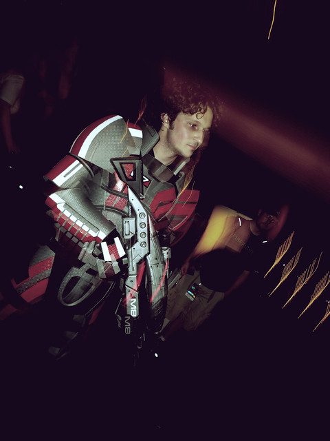
The completed suit! Not too shabby for a rush job, though there’s a ton more I would have liked to do if I had the time (painted panel lines, textured the undersuit, made a helmet, etc etc etc!) For DragonCon 2011, I am committed to spending more than a handful of weeks on my costume! Overall though, Foamshep was a blast to wear. The EVA can get a bit warm at times, but its a comfortable, low-cost suit that looks pretty convincing. Also, you don’t have to worry about breaking any pieces if you drop them.


Below are a few shots from DragonCon – credited with them are their respective owners on Flickr. I’ve got a photoshoot scheduled with the Jack cosplayer in the shots below, so look for that soon!


And another pic from Scenemissingmagazine on Flickr – Thanks again for the awesome shots!

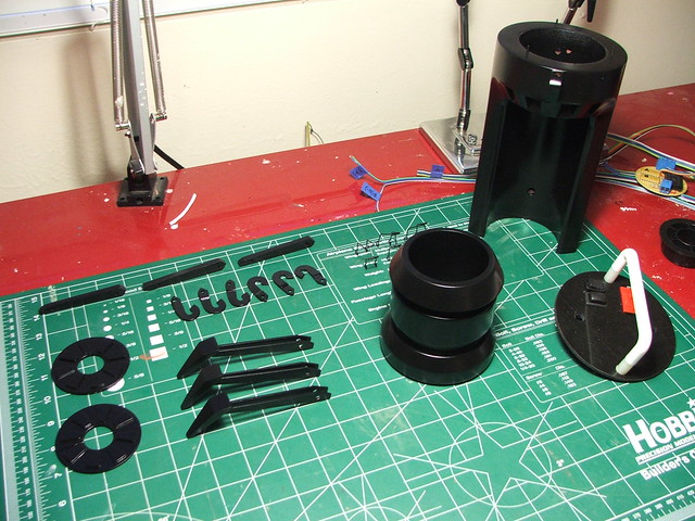
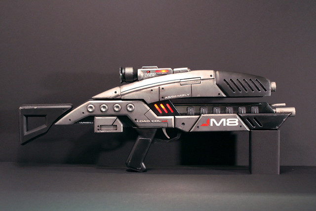
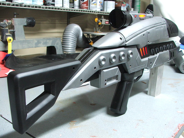
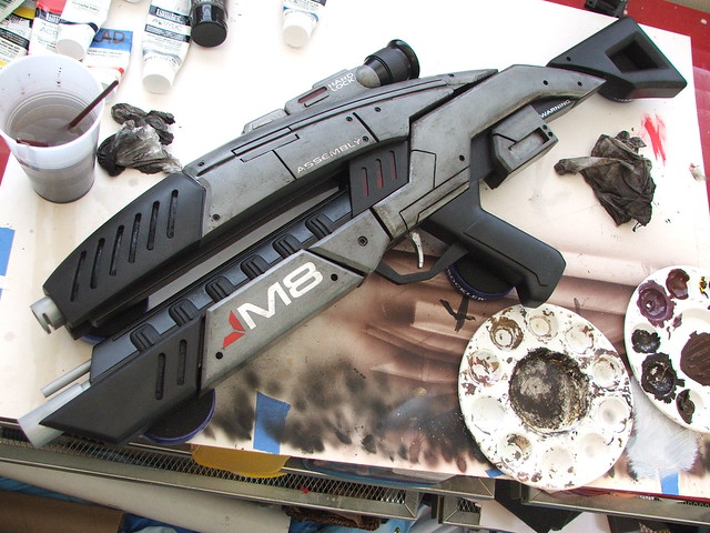
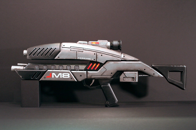
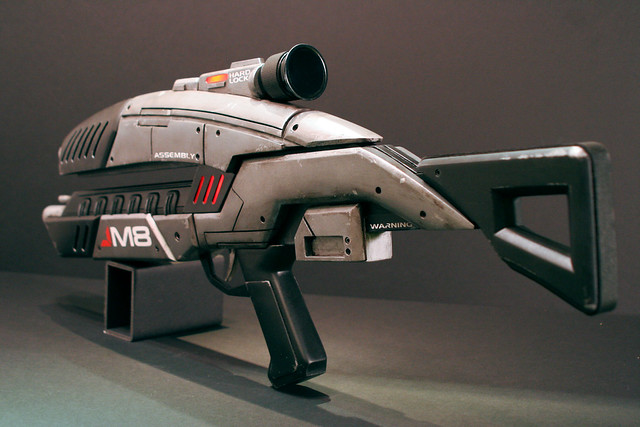
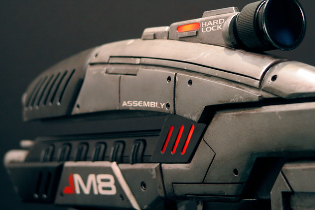
Mass Effect M8 Avenger Assault Rifle
It feels good to be able to build some stuff for myself again! The Daft Punk helmet was my last active commission for a little while, and for the next few months, I’ll be concentrating on personal projects…. like this one.
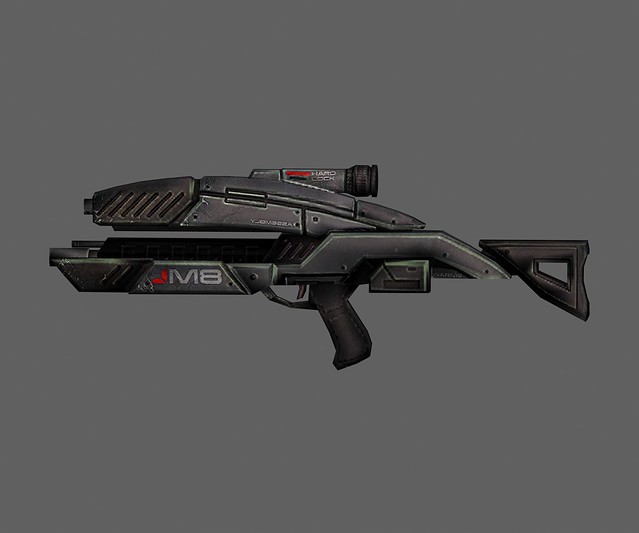
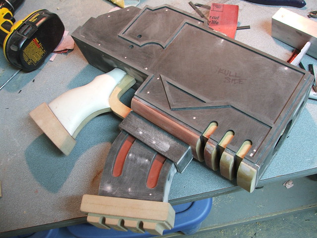
I’ve been a huge Mass Effect fan for a while now, and with the release of the second game I knew I wanted to take a crack at building some of the weaponry from the ME universe. As a bit of a personal challenge to myself, I decided to construct this gun from as much of my existing materials as possible. That is to say, 95% of what you see here is scrap I had in my shop from other builds. In the end, the entire piece only cost me $28 in raw materials.
 Note: if you email me and ask to buy this gun for $28, I will say yes; I will then take your money and mail you a box of wood shavings. You have been warned.
 So, here’s how it came together.
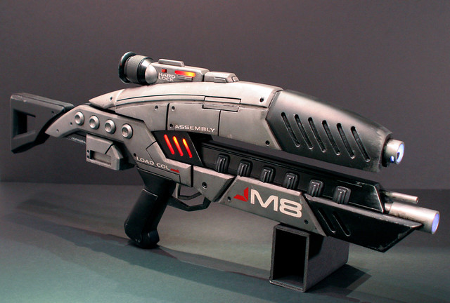
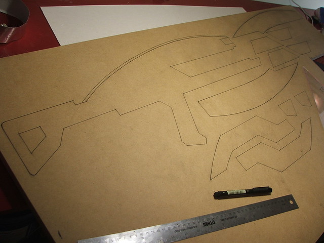
First off, as with everything I make, I drew up some blueprints. Those with a keen eye may notice that my illustrations don’t match up 100% with the reference image above. This is because the M8 in the game renders and the M8 on the box art have several differences. My version above is an amalgamation of the two.
I had a huge honking sheet of 3/4″ MDF left over from the Laser Rifle project; Onto this I sketched out the various parts. My plan was to have a central “spine” that all of the outer components would slide onto, forming the organic shape of the M8.
After trimming, parts that needed to be symmetrical were clamped together and sanded down along their edges to make certain they were as exact as I could get them.
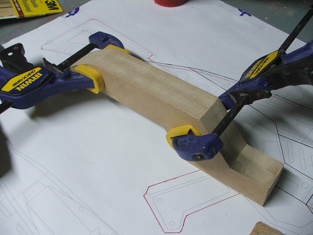
Here’s the rough parts laid out onto the center spine.
Next step was to glue and clamp these pieces together around thin strips of MDF that would serve as the center sections. This would eventually leave these pieces looking like a bunch of u-channel MDF chunks.
After drying
Additional details were added by either shaving down the existing blocks, or by adding 1/4″ MDF pieces to the outside of the forms and taking away from those. The ability to remove whatever piece I was working on from the center spine was a HUGE help in shaping these.
The upper receiver was shaped mostly on a belt sander, but some detail work was done with a palm sander, and eventually a sanding block to refine the shape.
EVERY edge on this thing is beveled! this was all done by hand with a dremel tool. Because of the strange angles of a lot of the pieces, I couldn’t use my table router.
For the lower barrel shroud, I used some scrap pieces of styrene and sintra formed around an MDF base. This is the interior – the repeating trapezoid shapes make sure the angles stay consistent.

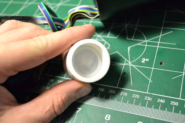
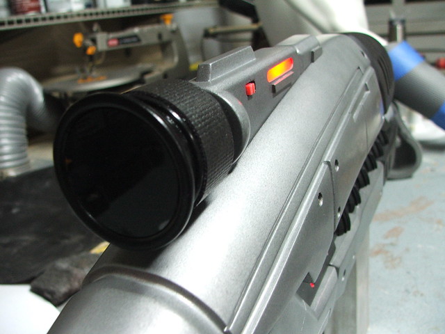
I also used some more scrap styrene to vac-form the scope assembly that sits on top of the upper receiver. These were formed around MDF bucks, and the dome shape on the sides was made from vac-forming the end of an engraving tool handle cap.

I also busted out the lathe to take care of the scope and the small cylinders on the right side of the gun. The scope from laminated sheets of MDF, and the cylinder master was made an old banister support. Really.
For the “grip” on the scope, I found some leftover rubber material used to line the insides of toolbox drawers. I think this was part of another project, but my toolbox drawers are also without liner, so who knows?

The lower grip details needed to be slotted to receive the lower barrel shroud and lower barrel assembly. The latter was made from some PVC pipe bits I had in my “scrap plastic” tub.
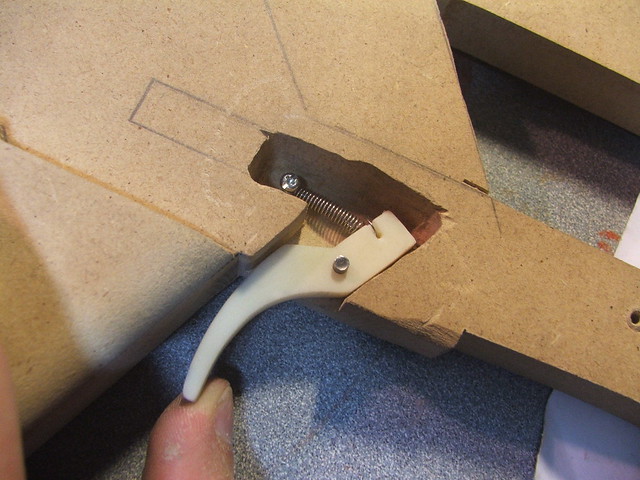
A trigger was made out of a delrin bar, and a recoil spring salvaged from a dead RC car. This created the trigger assembly.
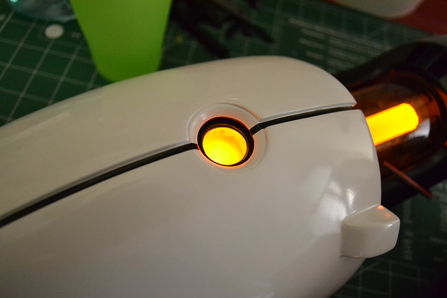
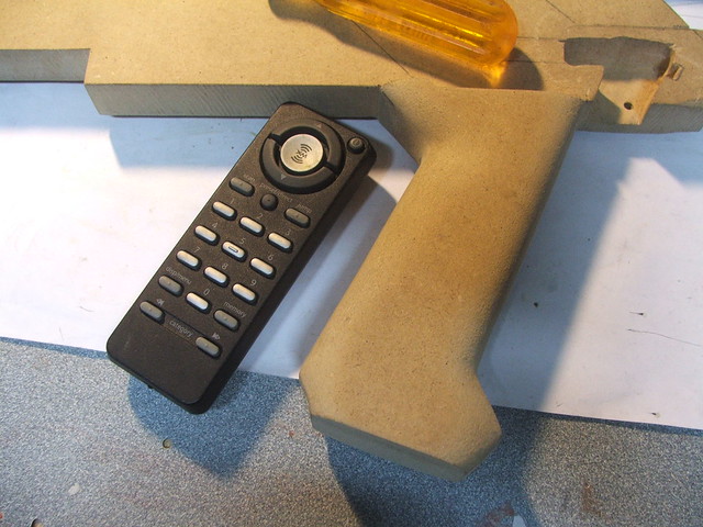
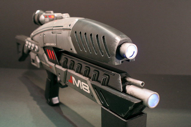
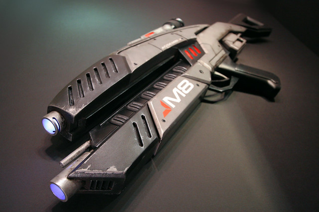
I decided I wanted to have the gun light up red in the sides and on the scope as it does in game. Additionally, to simulate “muzzle flash” I would add 3 LEDs to both barrels which would illuminate when the trigger is pulled. I added a small pushbutton switch at the front of the trigger to make the lights work, and for the battery compartment, I scrounged a double AAA cell holder from an old XM Radio remote control. This was countersunk into the handle.


THIS PIECE TOOK FOREVER! Oh man, the angles… It was very convenient to be able to shape pieces since I could remove them from the gun, but because nothing ever went back on exactly as it did before, a lot of times the alignment would change in test fitting, and I’d have to shave the edges down or move things around again. The result you see here – three pieces of styrene, took me almost an entire evening to get right.
After more beveling and shaping, this was the result!
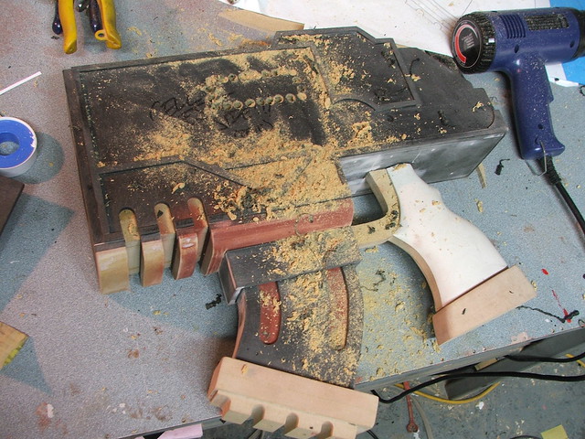
Using a dremel tool, I started carving the panel lines.
The front “vents” were made by drilling holes at the top & bottom, then using a dremel tool and cutoff wheel to connect the dots. The material on the inside was cut away with an engraving bit.

The first coat of primer on MDF always looks ugly. This also marked my first expenditure – 2 cans of Krylon Ruddy Brown, nearly $5!

After one pass with sandpaper and a little more primer, you can see how much better the pieces look.
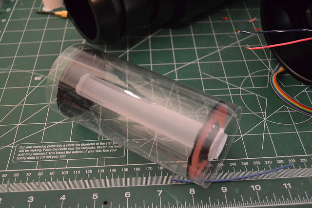
I used some spare LEDs I had left over from Big Daddy for the illumination in the center chamber. An old mobile from IKEA lent a few pieces of red translucent acrylic to tint the lights even further.

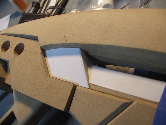
Additional details were added in styrene sheet.
For the details on the lower barrel shroud, I made a master piece out of ABS and styrene, then molded it and make 12 copies. The puck next to it is for the 4 cylinders on the right side of the gun.

Then the fun part. Primer, sanding, spot putty, repeat. About 4 passes and I had a pretty smooth piece.
I didn’t want to go buy any perfboard, so I once again reached into the scrap plastic bin for more styrene. By drilling holes and routing the leads of the LEDs in a weird little maze, I was able to make some halfway decent little dead bug boards. I made 2 for the barrels, one for the center section, and another for the scope light.
A few more details needed to be added in styrene. The vents in the front grip aren’t perfectly canon, but since this was a personal build I decided to add my own touch to it. Also, I cut the gap way too deep on that center section, and this was the best and fastest way to hide it! A great teacher of mine once said “Celebrate the Intersection. The more you try to hide something, the easier it is to see” Also… the small barrel there is an old ballpoint pen.

The battery cover was also made with some scrap styrene, by heating it and forming it to the shape of the handle. A styrene box on the inside keeps it locked in place.
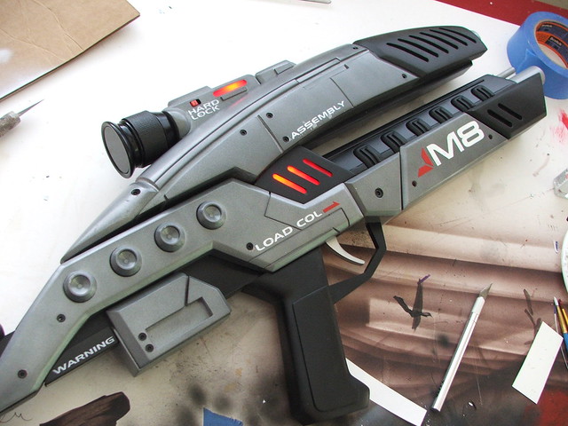
Onto paint! I had scrounged some free Ace Hardware offbrand from an old job at my office, which served as the rather bright silver basecoat. To tone this down, I dusted it with Rustoleum hammered spraypaint, then Krylon clearcoat. The gunmetal color you see here is the result.
The upper front receiver, rear stock, grip, and front grip were all painted with Plasti-dip spray to give them texture and a rubbery feel. This was another expenditure… up to nearly $10 now. All parts not painted with silver or plasti-dip got satin or flat black, depending on their location.
The scope was finished off with a piece of PETG (left over from Big Daddy’s viewports) pained black on the back to be as glossy as possible.
To control the electronics, I returned to the dead RC car and stole the switch from it. It even came with a nice plastic housing! This was placed in the scope mount. As you can see, i didn’t have any shrink tubing handy… so the leads were isolated with hotglue. Horray cheap budget electronics!

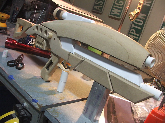
Final assembly after paint
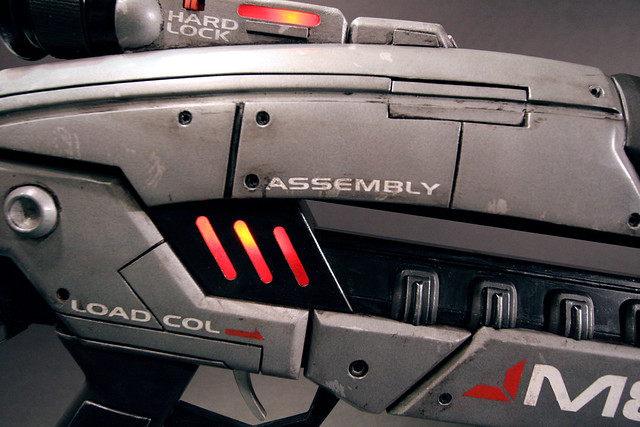
It looked good, but needed weathering. First though, I called up the shop that does all my vinyl – Signs Now Atlanta – and had them cut some stencils for me. I designed the decals for the M8 in illustrator, and the guys at Signs Now cut them in vinyl for me to use as templates. After sticking the vinyl to the piece and painting over with enamel paint, the mask was removed to show clean, crisp lettering! The nice part about this is what they’re more permanent than vinyl decals, and I can control how “weathered” the paint will be.
After that, it was time to weather it. I spent some time recording the entire weathering process for those interested, and in the coming weeks I’ll be editing that into a time-lapse video to show the overall technique I use. Don’t expect magic though, mostly it just looks like this:
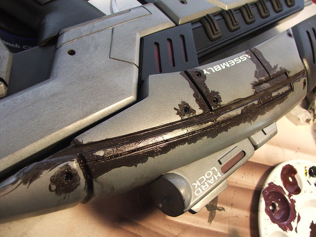
My initial pass was a bit heavy with the dirt – my favorite comment about it was “I don’t think I’d trust the fate of the universe to someone who doesn’t know how to clean their gun.” This was a good point.
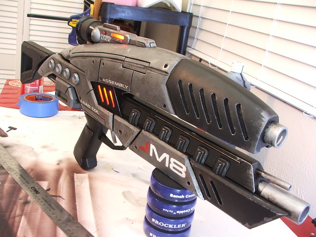
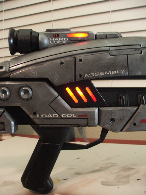
After pulling back the dirt and grime a bit though, I think the final result really shines. It looks well used, but also well cared for. The finished piece!
More pictures, and in higher resolution, are available on my flickr page!
As always, thanks for reading!

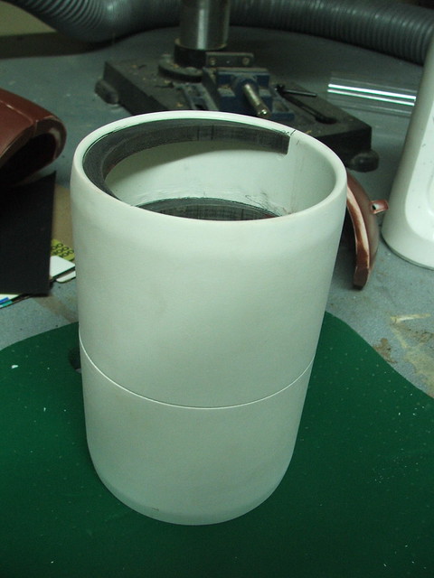
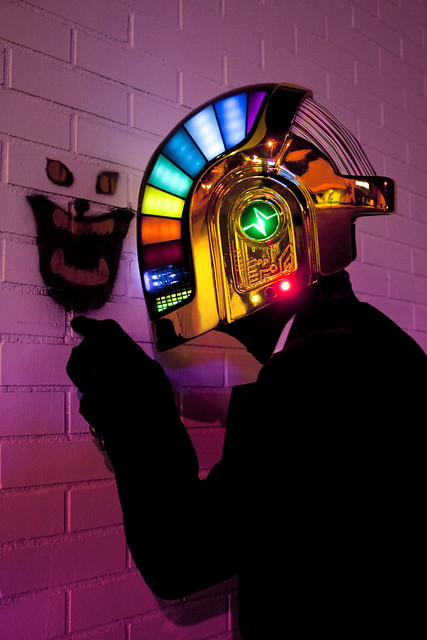
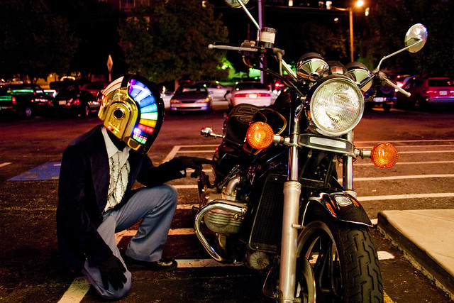
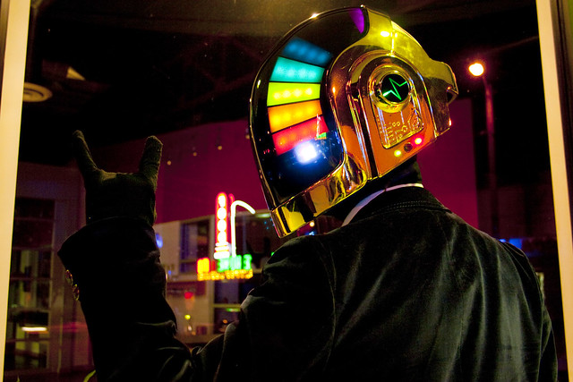
Daft Punk: FINAL!
Its been a long road. Seventeen months, countless hours, multiple dead ends, hundreds of lessons learned, and one helmet made. In the past two installments I’ve discussed sculpting, resin casting, chroming and vacuum forming. This is where the magic happens though… Illumination.
Build Archive: Part 1 – Part 2 – Helmet Q&A
If you want to know the details, grab a drink and follow along. For those of you who prefer the “instant gratification” route however, indulge yourselves in the following. Want more without reading all the boring build notes? Scroll all the way to the bottom for more prettiness, or visit my Flickr page for higher-rez pics:
Want to learn how to make a daft punk helmet in 3 minutes? Don’t blink.
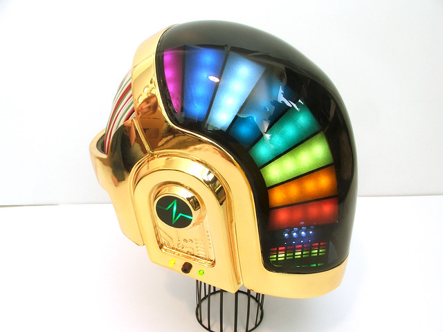
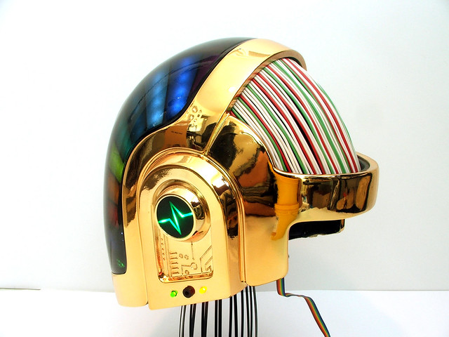
Now, for the build. We last discussed the golden bucket nearly a year ago. It was a last-minute test piece with a webbed visor and so-so chrome. The wiring color on the rear dome was incorrect, and the visor was tinted much too dark to see out of comfortably.
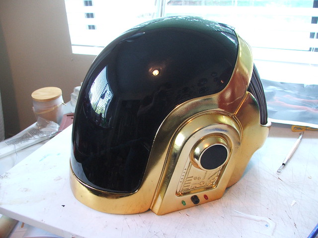
I set about pulling another copy.
This time the chroming task was handled by yet another shop – Creations N Chrome in Valencia, California. After an initial teething process in which we learned NOT to bake the helmets in an oven for them to dry, I was treated to one of the glossiest painted chrome finishes I’ve seen yet on my hand-sculpted form.

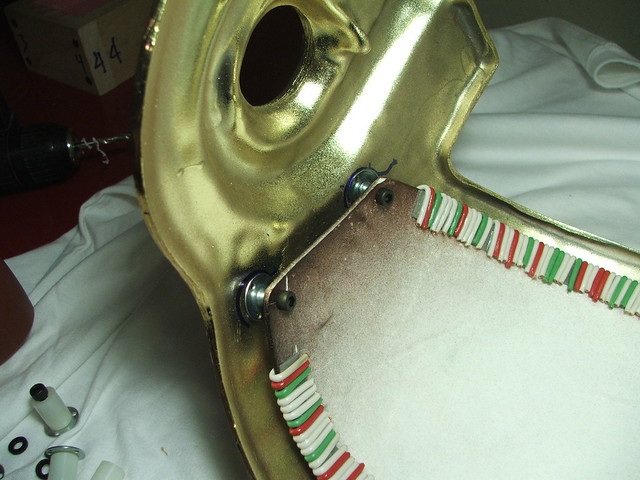
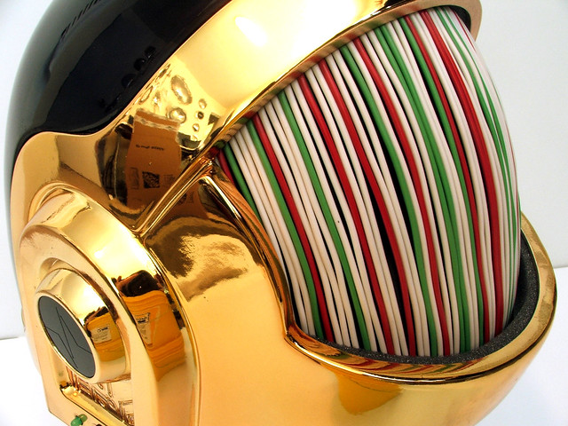
I also took this time to create a color-accurate wire dome for the rear of the helmet. Despite the holiday feel to the color scheme, its canon-accurate to Guy Manuel’s actual piece. In it went.
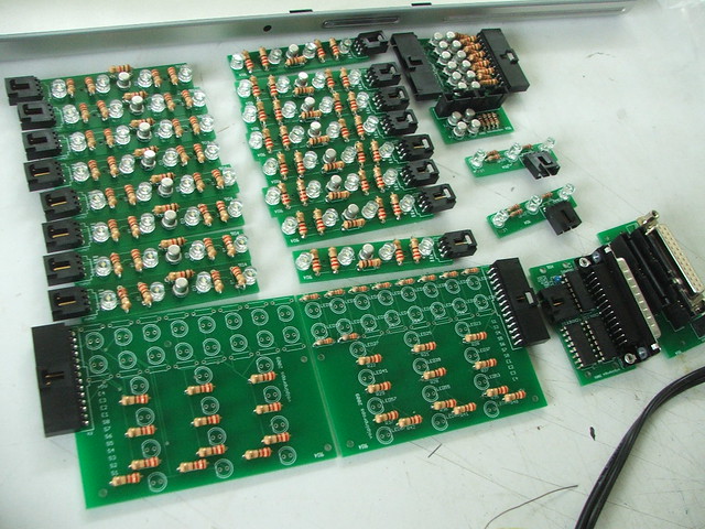
Yes, I promised you pretty lights. First, I had to teach myself to design circuit boards. After some research online, I found a program called Eagle from Cadsoft, and set about learning the interface. Many of my boards went through dozens of revisions as I found ways to make them smaller and more efficient. Here are a few shots of the final designs (top silkscreen and top copper only)
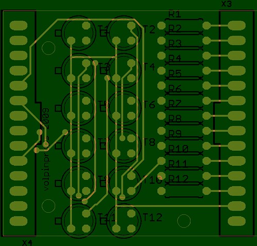
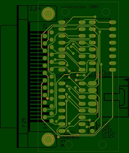

These were sent out to a company called batchPCB.com for printing. 5 weeks later, I had my boards! In the interim, I also lived on the Digi-Key website. All components except for LEDs were purchased through Digi-Key. LEDs came from Superbrightleds.com. I know it sounds like I’m hocking just about every single place I used here, but I’m bound to get emails about this eventually. Hopefully if I toss all the info out there, it’ll help other builders when they give it a shot.
So, with boards and components finally together came the soldering.
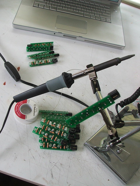
…and more soldering…

…and then some more.
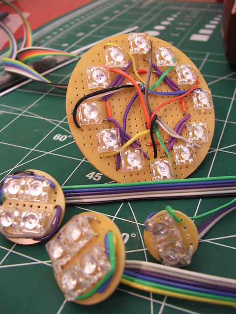
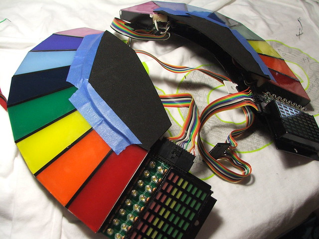
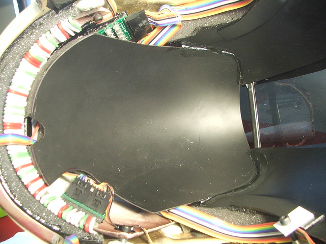
Once the boards were made, housings for the colorbars were built from styrene sheet.
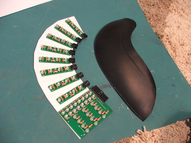
These were mounted to a vacuum-formed black styrene dome to make sure their shape lined up with the helmet.


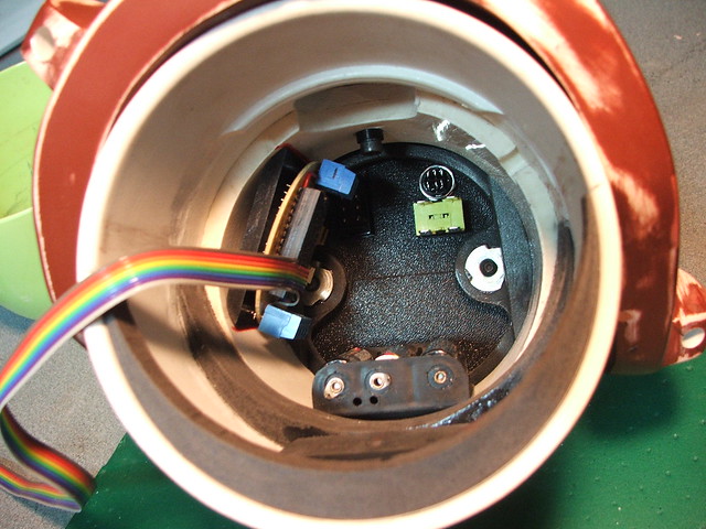
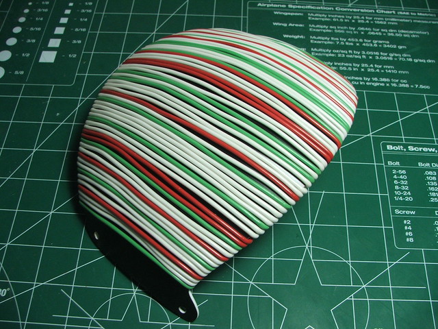
Having the housings built meant I could start building the wiring harness for all the lights. There is over a mile of wire wrapped around the inside of this dome.
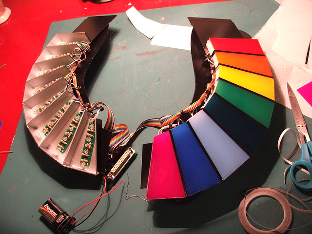
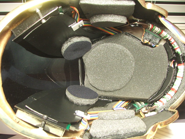
To diffuse the light inside the housings, white foam pads were placed over the LEDs. These each had corresponding gel sheets that would eventually be glued over the LED boards and foam.

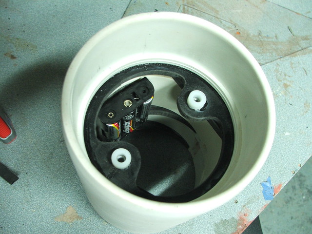
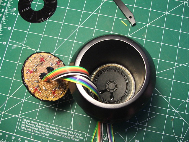
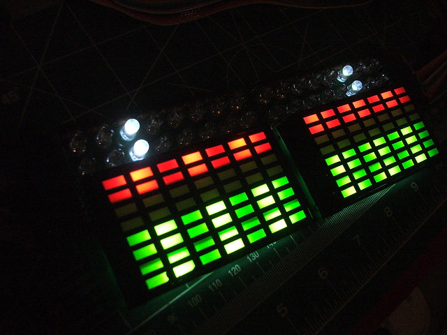
Here’s the rainbow lighting rig being assembled.
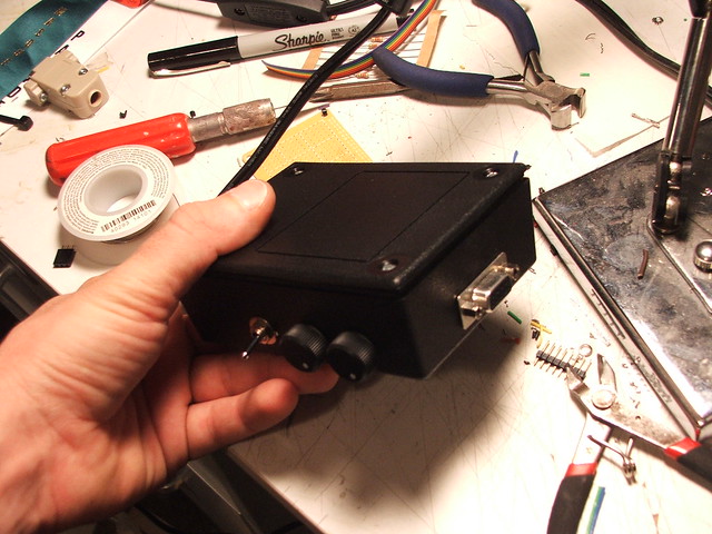
All of the signal and power would come from this black box, which houses the Arduino and AA batteries. A DB9 serial connector bridges the harness and the Arduino. There are three controls on the box – one switch that turns the lighting on and off, and 2 potentiometers which change the speed and pattern of the lights.
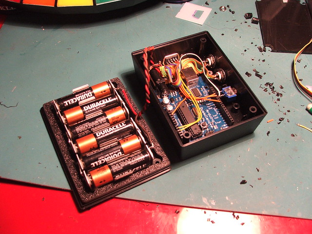
I have to give a MAJOR shout-out here to James Moss, who programmed the Arduino for me. I discovered pretty early on into this project that I had no mind for coding whatsoever, and set about finding someone who did. Thanks to YouTube, I ran across James’ own Guy helmet build and asked him if he could program my lighting array. The results you see in the videos below are examples of his stunning work.
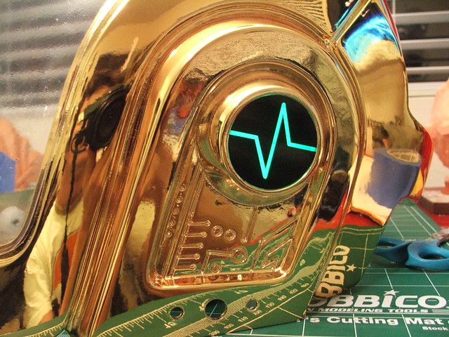
The last of the lighting was the color bars at the “chin” of the helmet, and the EKG meters in the ears. I sourced a local printer to laser-cut vinyl decals for me, and adhered these over translucent white acrylic to make masks for the LEDs.
When mounting the lighting rig, I wanted to make sure no light escaped into the inside of the helmet. All of the light areas were blacked out with thin foam 3M weatherstrip adhesive to make sure they stayed put.

Both the lighting rig and the rear wire dome were affixed to the helmet using T-nuts and allen screws. The bases were glued in place with plumbing epoxy.
After the lighting rig was secured, I started routing wires and mounting the boards.

Not wanting these to get damaged, I used a scrap piece of formed styrene sheet to make a protective cover which would keep the boards from getting knocked around or broken.
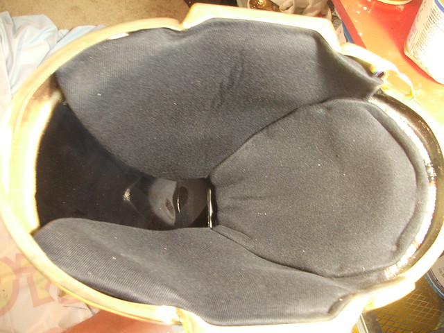
On top of this and on the sides of the helmet, I added layers of foam padding to grip the wearer’s head.
And finally, the inside was fully lined in automotive headliner fabric for comfort and style! Despite how it looks, visibility is actually quite good! Hearing anything with all this padding around your ears? Thats another story.
The first test-fire of the final piece:
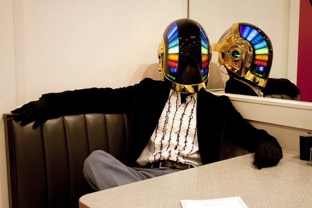
The final piece. Finished and it feels so good. If anyone is going to ComicCon 2010, you might see this thing in person!

Below are a few pictures taken by my friend Jennifer Barclay around Atlanta. I managed to cajole her into following me around in the ridiculous humidity, taking shots and answering all sorts of “what is that?!” questions. My last day with the helmet was a memorable one, and her shots are truly fantastic.

 This has been one hell of a ride, and easily the most monumental replica project I’ve ever undertaken. Higher resolution pics are available in my Flickr stream (up to 2272×1704 for you big-screen people!)
As always, thanks for reading!