
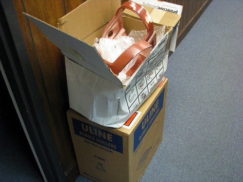
Budget Build Mini Vacuum-Former
I have long wanted a vacuum-forming machine of my own, and after scouring tons of resources online, I finally decided to try my hand at it.
My former is a little bit different from others I’ve run across. My wife and I recently received a new toaster oven for our wedding (Thanks Cindy, Susan and Terri!) so the old one that followed my wife through college was now up for harvesting. I decided to take out the heating elements – these being often the trickiest part of most people’s vac-former builds – and make myself a vacuum-former around them. This limited me to the size of the heating elements, but since this is my first ever attempted vac machine, I figured it couldn’t hurt to start small.
Here’s a few helpful links I scoured when doing research for my build:
First thing was first: I had to dig the coils out of the old machine. The flash in the picture makes it look worse than it was, but we’re talking about 5 years worth of corn dogs and mini pizzas here. This thing was nasty.

And the guts I excavated. In the end, I didn’t end up using the temperature control switch or the timer. The “bake, broil, toast” is only a rotary switch that turns individual heating elements on and off, so that was scrapped as well. The wires had a nice heat resistant shielding on them, so I re-purposed those later. They even had their very own fancy ceramic posts!

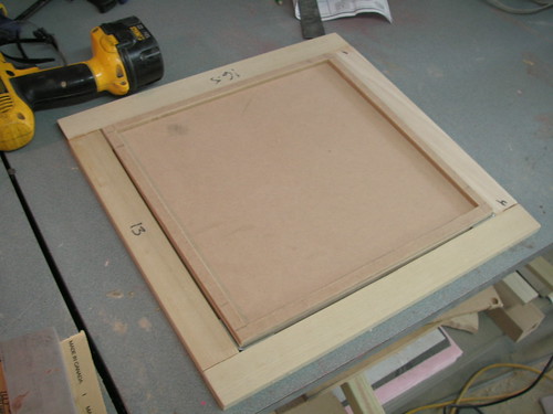
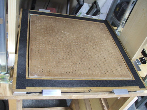
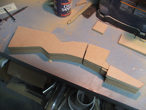
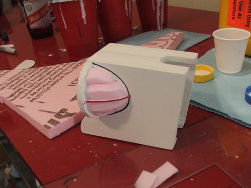
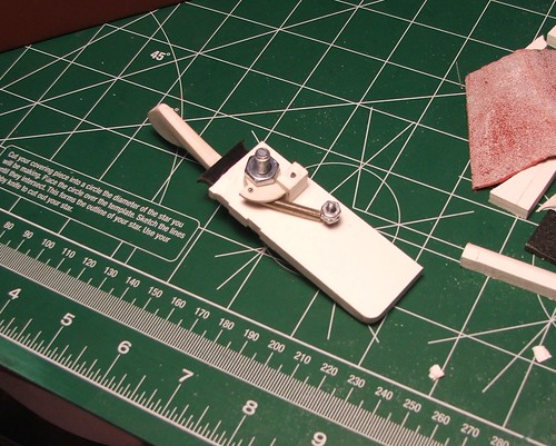
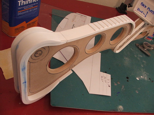
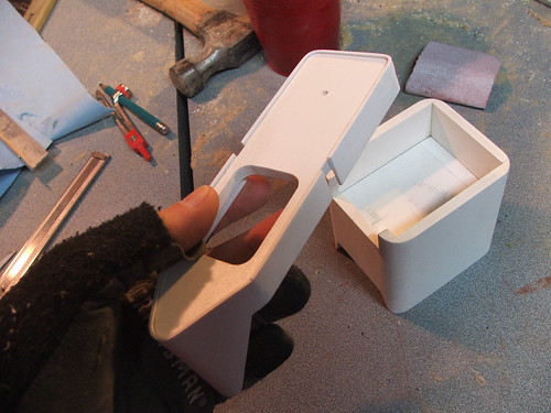
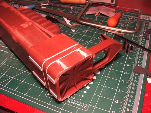
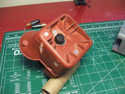
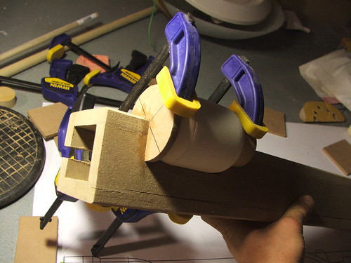
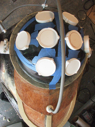
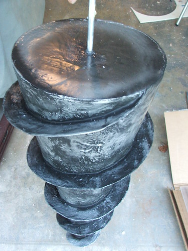
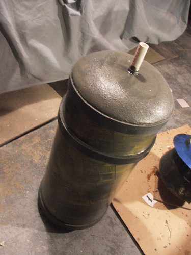
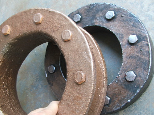
The heating elements dictated the size of the oven box, which itself dictated the size of the frame and platen. In the end I would up with a 14″ x 14″ work area. This is the oven box going together – its a maple box lined with 2 sheets of 1/4″ hardibacker concrete board.

From the dimensions of the oven, I worked backwards to figure out the size of the platen and frames. Frames are also maple, held together with L-brackets and wood glue.
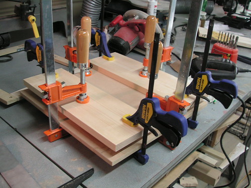
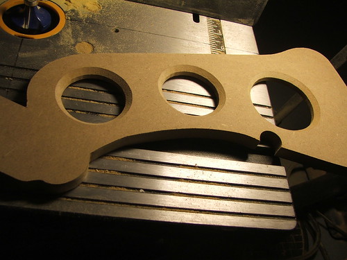
For the platen, I took two sheets of 1/2″ MDF and sandwiched them around a sheet of 1/4″ MDF. The 1/4 was trimmed to about 3/8″ wide to form the inner hollow area. These were clamped and set to dry overnight.
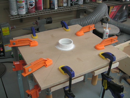
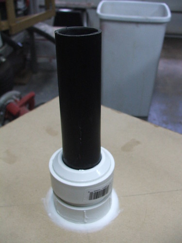
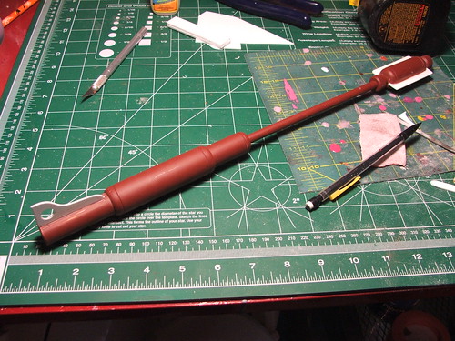
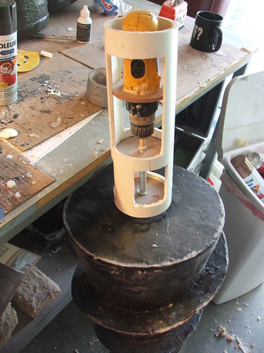
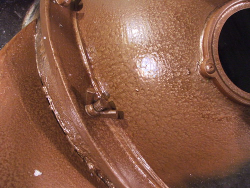
On the underside, I glued in a threaded piece of PVC and sealed the seam with caulk. The threads allow me to use a different adapter if I ever step up to a larger vacuum pump in the future.
This is the cobbled-together adapter I’m using for now. All sealed with caulk as well, it pressure fits onto my shop vac hose.
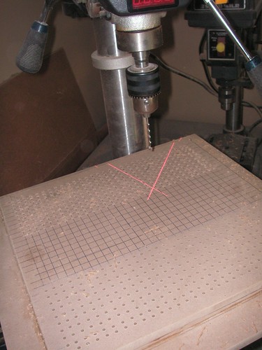
After this came the drilling. And then more drilling. And some drilling after that. I don’t know what I would have done without the laser guides on my drill press. The holes are 1/8″ and spaced every 1cm. This was based on my “well, that seems like a good idea” research, and some hinted-at suggestions online that smaller holes over a larger area work better.
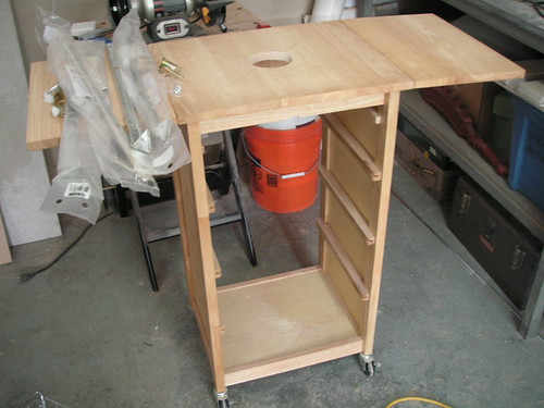
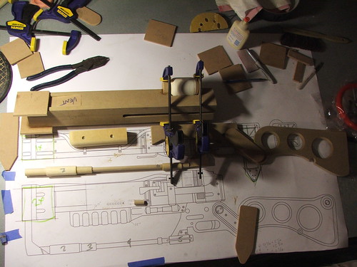
I got the rolling table when stopping by my parent’s house to pick up some of their old furniture. This used to be their kitchen telephone table. Initially, I had planned to remove the leaves, but had to include them in the end because the table top was about 4″ too narrow.
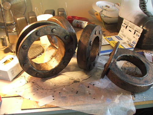
Here’s the freshly drilled platen and the oven box ready for mounting.

The oven box itself was mounted to the table using 1″ x 4″ poplar boards. 3″ long lag bolts were used to anchor the board to the sides, and it is held to the table with L-Brackets
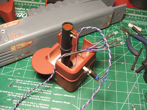
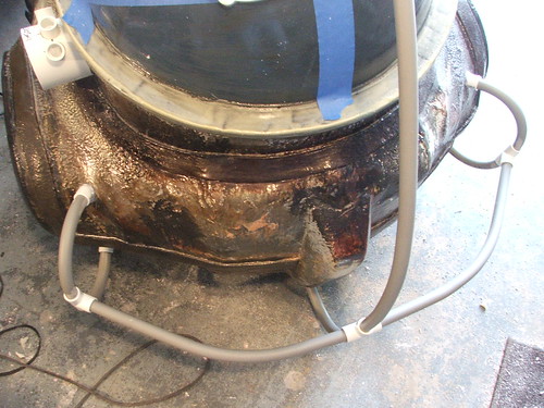
The inside of the oven before mounting the coils. I used fireplace caulk to seal the edges and seams of the hardibacker board. I also used this later to seal the wiring going into the oven.

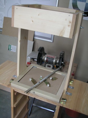
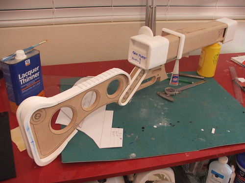
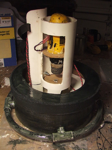
To articulate the plastic frame and move it from the oven to the platen, I tried something I’ve not seen used before: drawer rails. Similar to the idea of using toaster oven heating elements, this was something that seemed to make sense in my mind, despite never having seen it employed before on anyone else’s build. I bought 4 of these at home depot – 24″ long – and mounted them to the table and frames. They took some adjustment, but overall the result is great. Smooth action and dirt cheap!
I also stained and sealed certain pieces of the machine to protect them from wear and tear. The platen and frames were stained and sealed, while the oven and support arms got a coat of wood hardener.

For power, I ran a grounded line to a distribution box with its own outlet. The switch here controls the oven, and the outlet is used for the vacuum and heat gun. Don’t laugh at my rigged-up switch plate – I had a few of these laying around and I was trying to get this thing together as cheaply as possible!
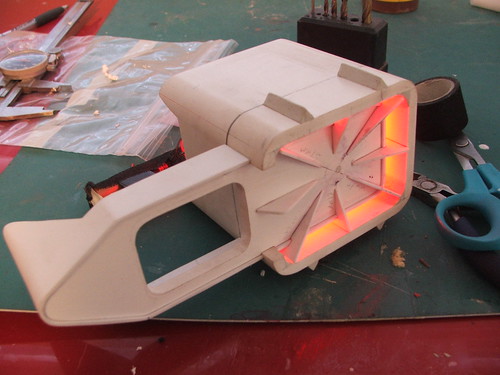
The oven wiring took a little trial and error to get right. Initially I had the entire thing running in parallel, but this tripped the breaker in my garage a few times, so I had to change the wiring configuration. I decided to do 2 coils paired in parallel, and then wire these two “banks” together in series. That worked out well, heating the elements nicely but not popping my breaker.

I had a few more things to do before firing it up. The frames needed a way to clamp to one another to hold the plastic in. I used some aluminum L-channel stock and cut 2″ sections from it. These were screwed to the frames and secured around the plastic with binder clips. I have somewhere around 600 of these things in my house from a previous project, so I’m always trying to find new ways to use them.

I also added a strip of closed-cell foam around the platen to help seal the vacuum when I lowered the frames down. Additionally, I added non-skid tape to the insides of the frames to better hold the plastic in place.
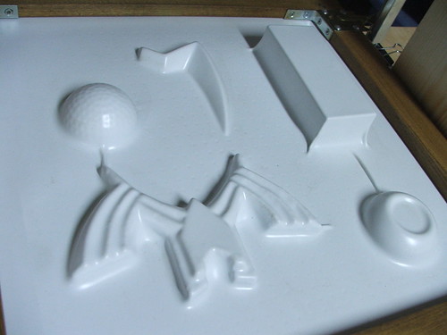
With that done, it was tine to melt some plastic! I grabbed some random junk from my shop and lined it up. Shown (clockwise) is:
- A filigree piece from my Hylian Shield build
- An aluminum block
- The mold master puck from Chell’s Heel Springs
- An old, damaged mold master from my Master Sword
- 1/2 of a golf-ball textured yo-yo

And the first pull! This was with .060″ styrene – I’m betting I can get really good definition with some thinner stock, but its what I had available.
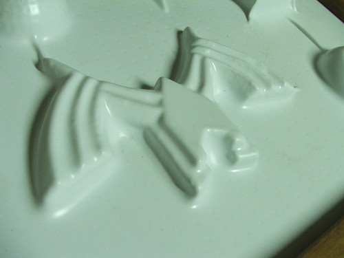
A close-up of one area. Not bad for a first pull!
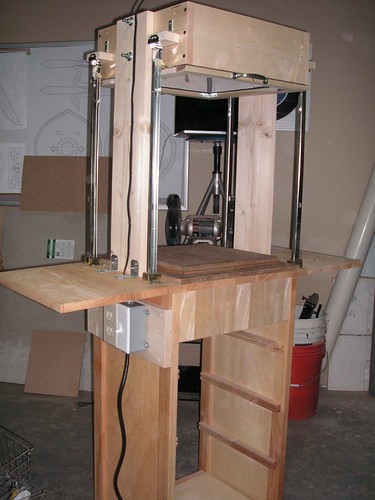
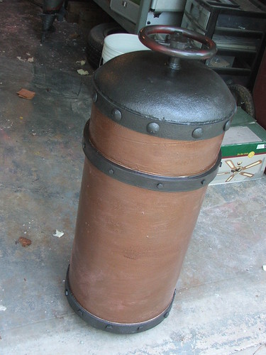
The finished beast, complete with battered shop-vac.

All told, this project cost me around $100. Most of the components I already had laying around from other builds, so I guess if you had to go from scratch, it might end up running $150-$175 or so.
- Toaster oven heating elements: free
- Table: free
- Shop vac: free
- PVC Fittings: free
- MDF: $18
- Pine/Poplar/other wood: $20
- L-Brackets: $15
- Wiring/Switches: $12
- Hardibacker Board: $8
- Caulk/Sealant: $5
- Wood stain/sealer: $10
- Various hardware: $2
- Drawer sliders: $4/ea
Best of luck fellow DIY-ers, hopefully we’ll start to see some more toaster-oven formers popping up in the future. As always, thanks for reading!

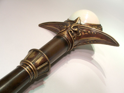
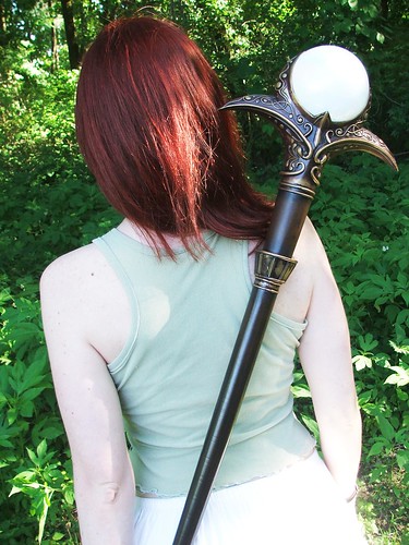
Light Staff (Final Fantasy XI)
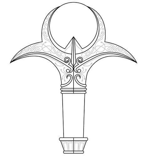
I was commissioned to make the Light Staff (Apollo’s Staff to those who only want the +1!) from Final Fantasy XI. FFXI came out in 2004, and the graphics aren’t exactly up to par with more modern games. As such, some artistic liberties had to be taken with the design of the ornamentation.
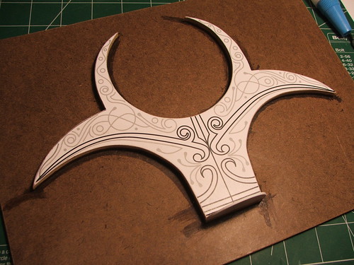
I traced the basic shape of the staff in Illustrator and set about designing the filigree ornaments on the staff head. I used a screenshot of a character wearing one of these staves to get the scaled size appropriate.
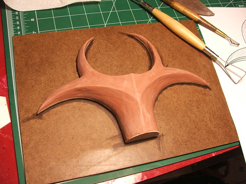
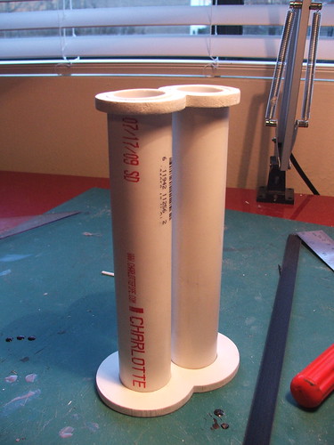
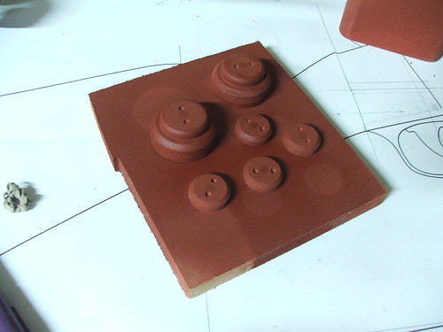
I decided to try a clay sculpt this time around, since the staff head has a fairly organic shape. First off, I printed out my blueprints and adhered them to a sheet of 1/4″ MDF. This way, my sculpt would remain symmetrical so long as I stuck to the edges.
The sculpt was done with Chavant brand medium weight non-sulfur clay (there’s a mouthful.) All in all, it was fairly easy to work with, and a lot faster to work with than if I’d tried to make the entire piece from carved MDF or foam.
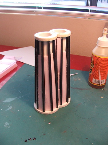
Basic shapes started rough, and I mostly just used my fingers to get the clay to the approximate shape.

As the edges got more definition, I switched to clay tools and sponges to smooth out the shape.
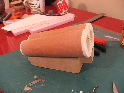
This is skipping a LOT of smoothing, adding clay, tooling, and frustration – but the final result can be seen below. I ended up lathing a puck out of MDF to take the place of the orb while I was sculpting. This was cut into three sections and the outside edges were sealed with wax to make removing the piece much easier without damaging the thin and fragile clay pieces surrounding it when I went to pour the mold.
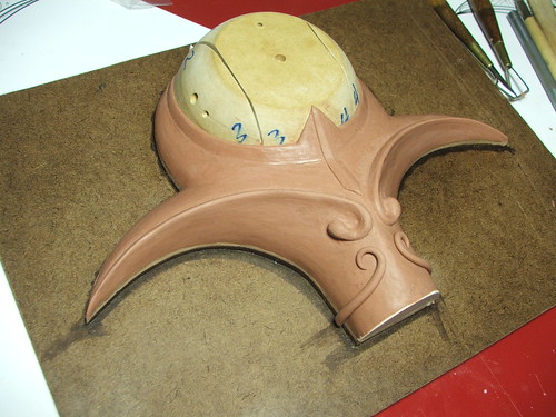
Here you can see the definition on the edge of the clay after the MDF puck was removed.
After the sculpt was finished, the clay piece was put under some Rebound 25 silicone rubber.

Once the mold was set, I pulled a resin copy. Details transferred very well, and this piece needed no cleanup at all.
Using my original blueprints as reference, I transcribed the filigree patterns onto the cast in pencil.

These lines were then (painstakingly!) carved out with a lino block carving tool.
The carved channels made it easier to line up the round styrene bars for adding the accents on top of the resin cast. Thicker parts – such as the curls at the center area – were added with apoxie sculpt.
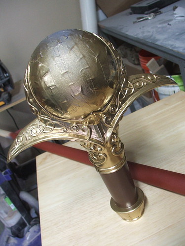
This piece was primed and painted, then molded in the same manner as the clay sculpt. I used a glass gazing orb for the central large bead at the top of the staff, and decided to create a mold of it as well so that I could make multiples later if I felt like it.
Two halves were cast in resin from the final mold and epoxied around the glass orb. The seams in the edges were then filled with apoxie sculpt.

After that, it was time for the most tedious part of the build… primer, bondo, and sanding. Repeat, repeat, repeat.

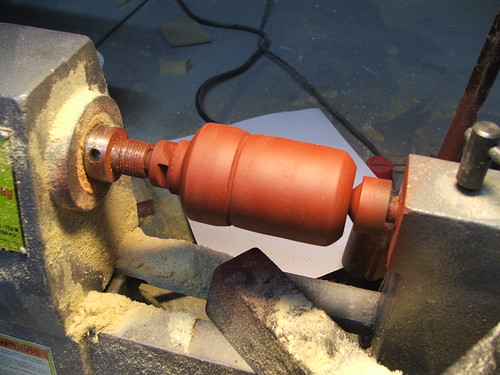
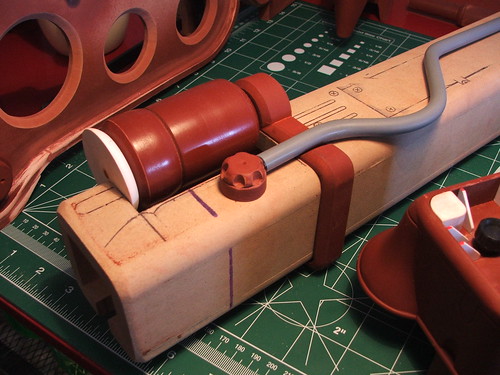
For the “neck” part of the headpiece, I lathed a pine block to shape, then added accents to the bottom area in half-round styrene.

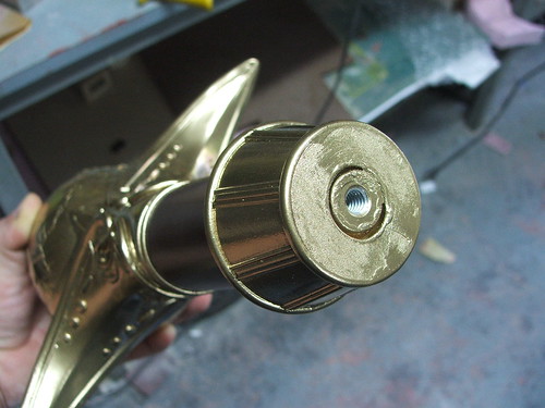
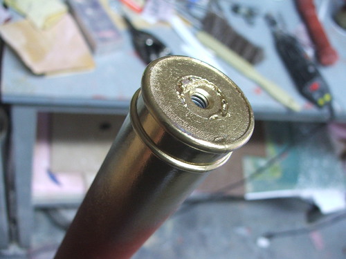
These two halves were joined together with blind nuts and threaded rod. After the glue on the blind nuts was set, both pieces were joined with epoxy.
The first coat of paint going on the staff head after all the sanding and prep work had been completed. For the brown, I used the same Krylon Fusion brown paint that was used on the Force-a-Nature build.
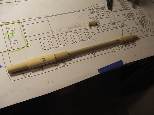
For the longer rod of the staff, I needed a tapered dowel that was about 40″ in length. Problem was, my lathe only has a 12″ working area. Solution?
Pool Cue!
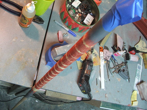
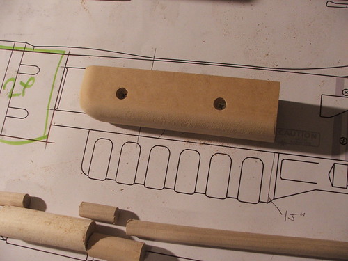
The divots in the handle of the cue had to be filled in, since the length of the staff rod is smooth. I filled these with bondo several times in order to get the edge as smooth as possible. This shot is from the first pass.

After the first coat dried, the brown area was masked off and the rest of the staff painted with Montana Gold spraypaint. This stuff is VERY shiny, and will remain that way unless you topcoat it with something else. I was going for more of an aged brass look for the final piece, so this got toned back a lot.
As with the halves of the staff head, blind nuts were used to join the upper and lower portions of the piece. These were left un-glued though, to help with shipping. The client can epoxy them later if so desired, or leave them loose if they ever decide to travel with the staff.
Finally, the piece was weathered with a wash of acrylic paints, airbrushed into the crevices and then wiped clean on the raised sections to give it an aged look.

The lower portion of the staff was weathered in a similar manner. After that, the two pieces were joined and the piece was finished!

The piece is over 45″ tall and weighs about 5lbs. Added after the fact was a small rubber nub at the bottom to protect the wood and finish.


More pics, and higher res shots are available on my flickr page if you’d like a closer look. As always, thanks for reading!

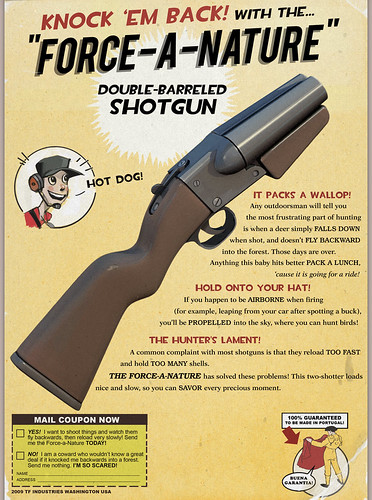
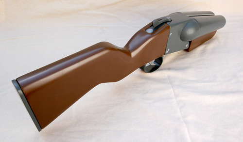
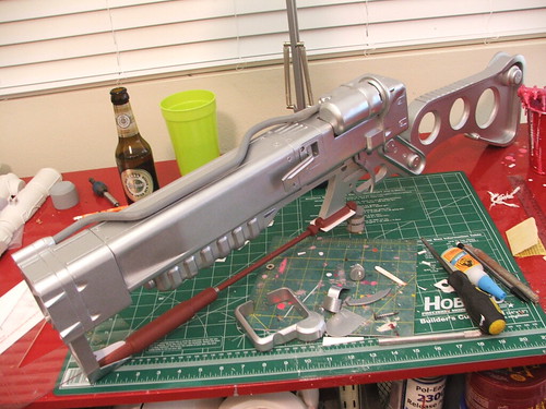
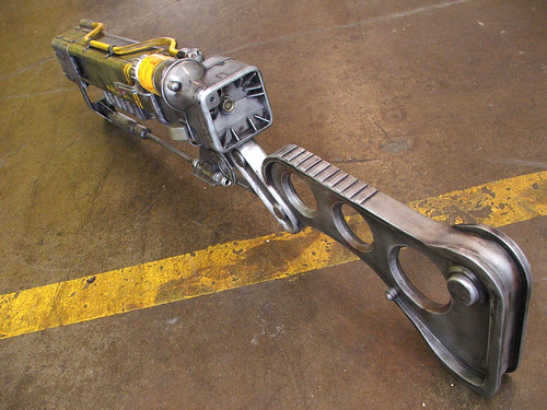
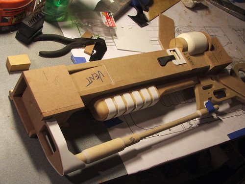
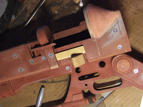
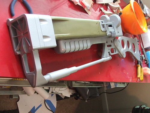
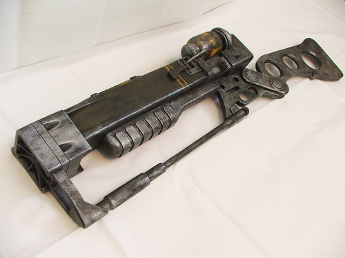
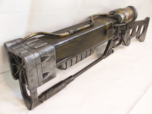
TF2: Force-a-Nature
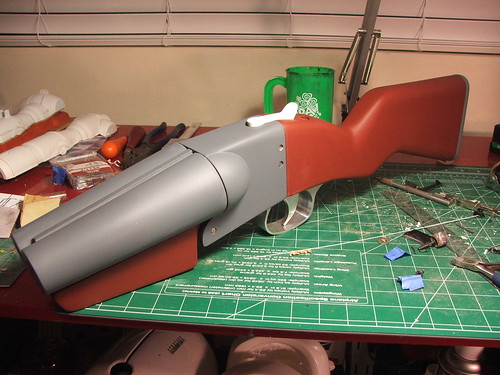
Any outdoorsman will tell you the most frustrating part of hunting is when a deer simply falls down when shot, and doesn’t fly backward into the forest. Those days are over. Anything this baby hits better pack a lunch, ’cause it is going for a ride!
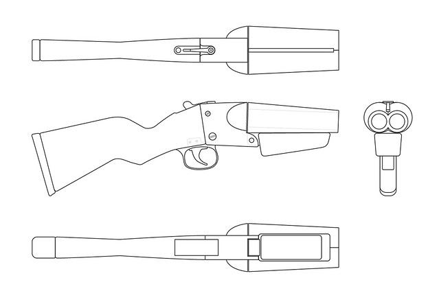
This is a very cool and ridiculously proportioned weapon. 7″ long barrels firing 4ga rounds and proportionally twice the size of regular rifle stocks, its comedy in overpowered shotgun form. How the Scout can fire this thing – from the hip – is anyone’s guess.
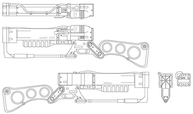
First step first, I made up some blueprints in Illustrator. The scale was determined by sizing up the scout to 68″ tall and measuring out the gun accordingly. The Scout, much like the rest of the guys in TF2, has HUGE hands which make the trigger and front grip assemblies respectively giant.
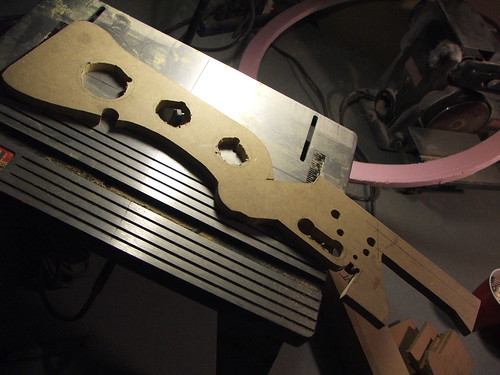
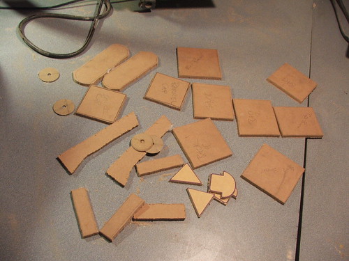
Starting off, I rough cut the stock and front grip out of 3/4″ MDF. Thinner sections were added in 1/4″ MDF to make sure I had the depth built out accurately.
These individual pieces were glued and clamped together to make large blocks. Eventually, I’d shave these down into their final shapes, but for the time, everything remained pretty chunky.

This is the front grip after some sanding. I added an MDF plate to the rear section to even this out and save myself a lot of bondo work. The piece sticking off the back will eventually act as the barrel hinge.

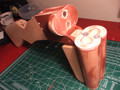
The barrels were an interesting challenge. Initially I thought of lathing them out of a solid block, then coring that block out for the inner barrel later. The more I thought about that, the less I thought I could pull it off well… so I tried something completely different and fairly strange.
I cut the front and back barrel profiles out of sintra. These are the upper and lower “8” shapes in the shot below. I then cut 1.5″ PVC pipe to 7″ long and glued the “8”s to the top and bottoms.
Strips of thinner sintra were trimmed in long thin triangles that matched the taper of the outer barrel, then glued to the PVC pipe. I also glued in wedge-shaped pieces of insulation foam to fill up the cavities in between these strips.
This was then skimmed in apoxie sculpt. The dented lines in the clay in the pic below are guide marks. I pressed a straight edge into the clay, making sure that the sides hit the two figure 8 shapes on the front and back. This indentation told me how much I needed to sand off once the clay was dry.

After a few hours of sanding I had this! Nice, smooth barrels, and as light as I could make two giant blocks of clay, too.
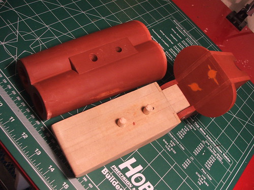
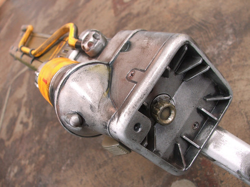
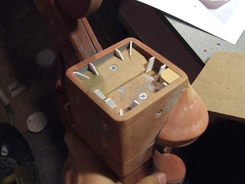
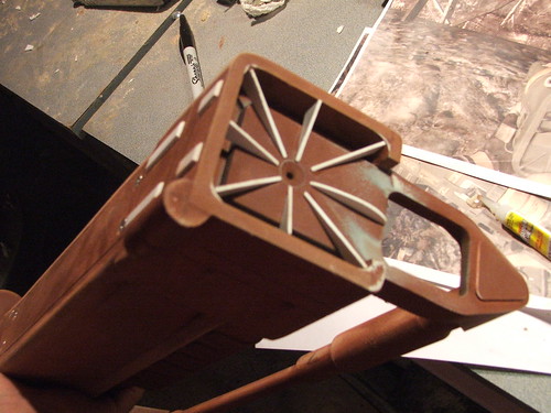
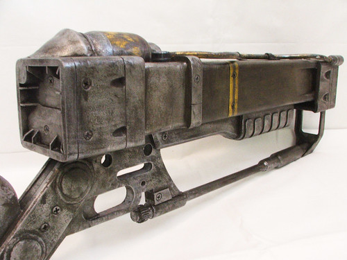
The center chamber was originally going to be MDF, but the gun needed to have a moving trigger and breech release lever, so I decided to go with something hollow instead. This box is made out of 1/4″ sintra. I used a similar process to the barrels to make the curved domes on the sides of the chambers.
The chamber section after clay and sanding, mocked up next to the barrels to check alignment.
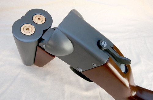
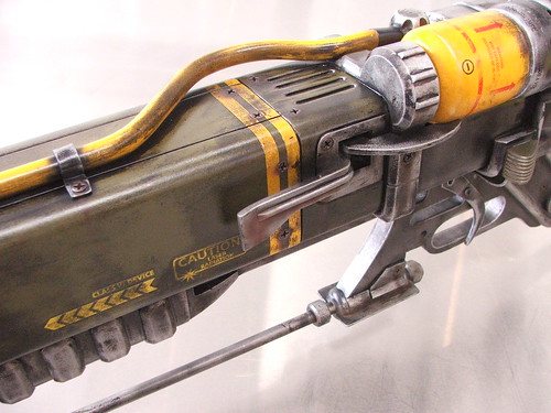
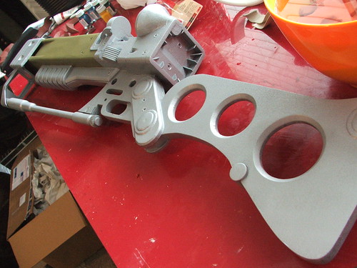
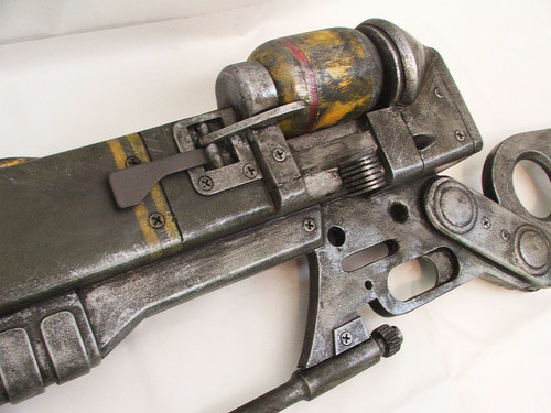
Magnets were added to the barrels and center chamber to hold the breech closed. I went with 2 neodymium 16lb pull magnets situated in the center of the assembly. You can hold the gun by the rear stock and these will keep the barrel closed well until you pull them apart. The best part is there’s no maintenance needed for moving parts!
The front grip is held onto the barrels with 2 wooden dowel pins in countersunk holes. These were filled with gorilla glue and clamped for final assembly. The orange areas in the shot below are from an earlier set of magnets that ended up being too weak to hold the chamber closed.
The rear stock was shaped with a dremel and an orbital sander. After poking around online and watching what people have done with DIY CNC milling machines, I can definitely say I’m saving up for one of those next. Shaping this by hand and getting the symmetry right is a pain in the ass.
The front grip was also shaped to better match the in-game shotgun. The sides were beveled slightly and the corners rounded as well.
For the butt plate on the stock, I shaped a spare piece of nylon stock I had lying around from another project. The two countersunk screw holes will be filled in later so the piece is flush.
After the stock and grips were shaped, I rounded the corners on the center chamber to match the contours of those shapes as well. I also carved out the area in the stock for the breech release lever. Toward the back of the center chamber in the shot below are 2 stainless steel pins which hold the grip and chamber halves together. This is a friction fit that was glued in place later.

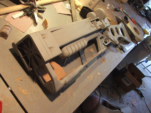
A fellow Portal junkie propmaker friend of mine offered to CNC some parts for me a while back, so I took him up on his offer for this build. He carved the trigger and trigger guard out of a block of aluminum for me based on a few drawings I sent him. He doesnt have much of an online portfolio, but you can see a kickass piece he made here.
The other moving part was the breech release lever. This was made out of layered styrene. The lever itself is spring-loaded and connected to a bolt on a copper tube that the assembly rotates on. The “guts” of the mechanism can be seen here:
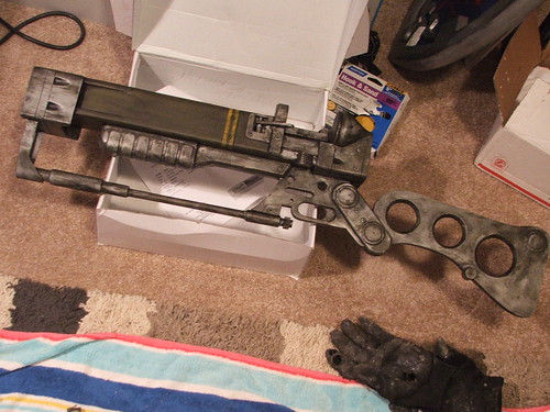
All of the parts were given a coat of primer close to the final shade, and test assembled one last time before final paint. The trigger mechanism fit perfectly, which is amazing considering it was machined in a different state. Often, even the parts I make for myself in my own garage don’t fit without at least some modification.

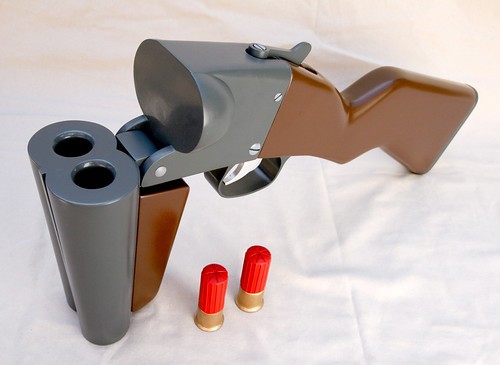
I also made a set of equally cartoony-sized shells to load into the gun. The first master was made out of lathed basswood and styrene.
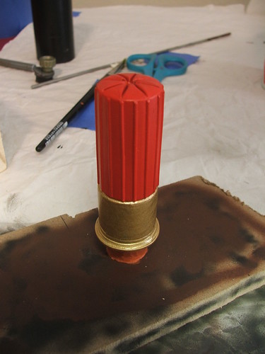
I made a quick mold of the one shell and cast 2 more copies in resin, which were painted to match.

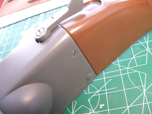
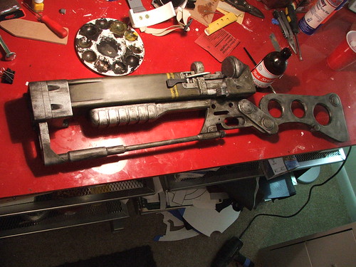
mmmm… chocolate gun parts. Krylon Fusion paint is niiiiice

The gunmetal parts of the FaN were painted with Montana brand paint, which I don’t think I’ll go with again. The color is excellent, but its far too difficult to get a nice, even coat. For $10 a can, its really not worth the hassle.

Lastly, the dowel pin holes were covered on the side of the gun with nylon screw heads painted to match. These were eventually topcoated with lighter gray testors paint to make them stand out.
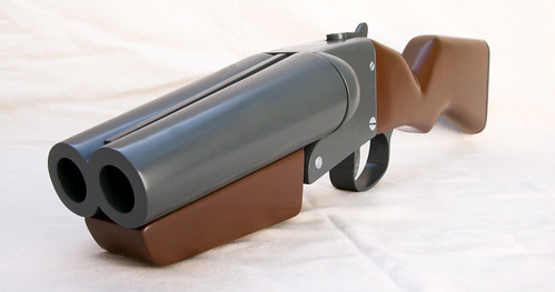
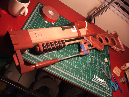
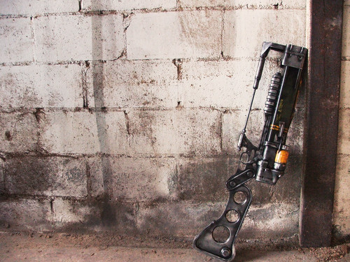
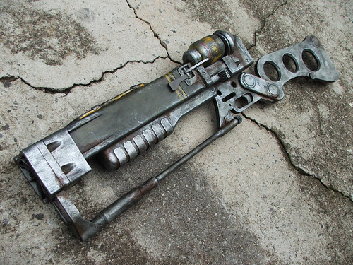
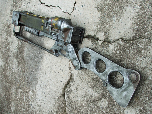
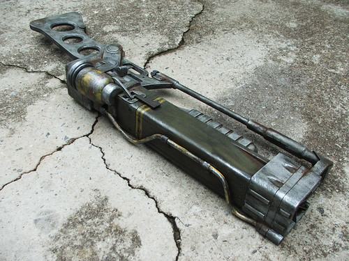
And the final product in all its backwards-blasting glory!


Higher-resolution pictures are available on my flickr page. As always, thanks for reading!

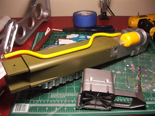
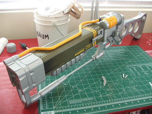
AER9: Once more, with feeling
If you’re familiar with my last AER9, you’ll recall that the project was completed in only 4 days. I recently had a chance to take another whack at it with a much more lenient deadline, and I’m very, very happy with the results.
The basic steps at the beginning were the same as my last build. Make a blueprint, transcribe it to wood, and start cutting, gluing and clamping.

I did discover a random and somewhat neat trick for scribing the lines on this though. By printing to vellum on an injket printer, I was able to directly transfer the pattern of the print from the paper to the wood. Using laquer thinner brushed over the ink, I burnished the paper against the MDF and the lines transferred perfectly! Made transcribing my blueprints MUCH easier.
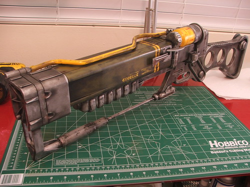
The main difference between this build and my last is the materials used. Outside of the stock base, barrel, grip and MF cell, all other parts were made from sintra, styrene, or aluminum. These materials can take detail much better than MDF which afforded me a lot of control in making the shape more accurate.
I also decided to use LEDs for a glowing barrel effect. This was a preliminary test-fire to see how the idea would work. In the end, I used the lens out of a laser pointer behind the center hole in the barrel to focus the light and make it brighter in that spot.
After the barrel and stock were shaped to the correct dimensions, I started adding details in sintra & styrene. The rounded edges on the back and front parts were made by gluing the sintra into a box and rounding the edges on my table router.

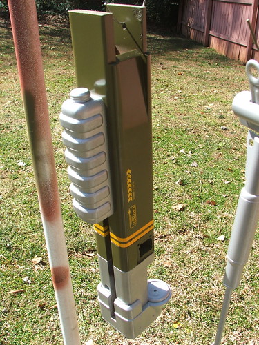
Another huge difference in this build was my new lathe. The AER9 has a TON of little rounded bits all over it. These were cut out of MDF or sintra. The microfusion cell is 4 pieces of MDF glued together and shaped on the lathe as well.
This rear knob is also lathed MDF. The tube which sits on top of the barrel is an ABS rod. This was a lot easier to shape than the 5/16″ steel tube I used on the last build.
Here’s most of the parts going on for a test fit.
The grip is an MDF block with sintra strips shaped over it. To keep a uniform shape, I heat-formed one sheet over the entire grip, then cut it into strips on my bandsaw.
The rear of the barrel is a sintra box with styrene accents. The curved part behind the MF cell was sculpted out of apoxie sculpt and sanded to shape.
Various other smaller bits were shaped out of sintra/styrene before going to primer. Below is the trigger & trigger arm, MF cell area, barrel, cell eject lever, and other bits. I also scribed the panel lines on the parts with a lino block carving tool I had left over from my art school days.
Another test assembly after all the parts had been primed. I had some really tight tolerances when putting it together, as the layers of paint actually made it quite hard to get the front and rear casings over the barrel. Yay precision!

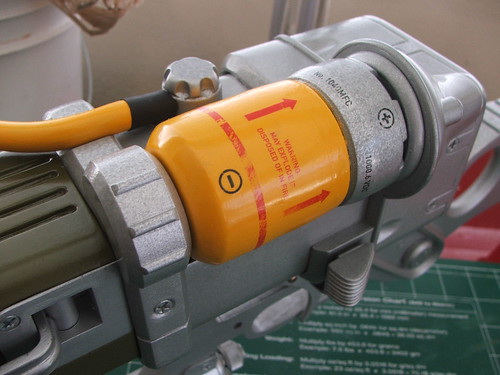
To power the LEDs, I used 2 AA batteries housed in an in-line battery holder. The knob on the back of the gun unscrews to reveal the battery door to replace the cells. I was very very happy with how this turned out. The LEDs are switched on and off by a hidden pushbutton switch on the bottom of the rifle barrel.

The last lathed part was the bottom support bar. This was carved from a pine dowel and cored out to receive a hollow aluminum bar. Styrene accents finished it off. I also found some knurled nuts to use for the two circular parts on the support bar and JB welded them in place.
On to paint!
The basecoat silver was done with Krylon chrome paint. After this, I dusted the surface with a darker silver by holding the can about 2 feet away from the part and spraying lightly over the entire surface. This gave the paint a stippled texture like cast aluminum would have (this is shown a little better on the front barrel casing in the shot below with the barrel painted green.)
Color was done with Testors spray paint for the barrel (which is annoyingly thin and loves to run) and Testors brush paint for the silver on the MF cell and upper pipe.
After this, each individual part got a coat of clear to protect the finish.
I know I’m going to get a ton of decal questions, so I hope this answers them preemptively. It seems like custom decals are the bane of every replica maker, and it took me a bit to figure out the best way to do it as well. As with my Portal Gun, the AER9 got water-slide decals on the MF cell for the warning messages, arrows, and stripe. These were designed in Adobe Photoshop and printed onto water-slide decal paper on a laserjet printer.

The barrel decals were done differently. The barrel was scanned on a computer scanner to pick up the color & texture of the paint. Then, I designed the side decals in Illustrator, taking them into Photoshop to layer them over the green background and weather them a bit before printing. These were output on adhesive-backed vinyl using a plotter, then applied to the gun. There is a slight seam line around the sides of these, but its only evident under close inspection.
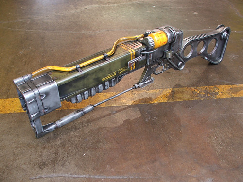
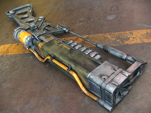
Here’s the gun all assembled and shiny brand-new! So pretty, so clean…

So needs a few coats of grime.
This was the first pass. Another new tool I had for this build was an airbrush. I’d never used one before, so this was as much a practice run as it was a weathering effort. It took some getting used to, but I was very satisfied with the results.
NOTE: If you don’t seal inkjet decals before acrylic paint weathering, they will run & bleed! This is why I clearcoated the gun before this process.
I also made a display board for the gun to sit on, in maple. This was stained satin black.

Here’s the final shots of the gun after all the weathering was completed and given another coat of clear to protect the finish. I am very glad I got to revisit this piece, but I don’t think I’ll be making another one. 2 was plenty for me, and its time to try another project with my newfound techniques and materials.
These pics and more build images are all available on my flickr page,in much higher resolutions. Thanks for reading!

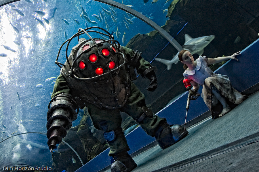
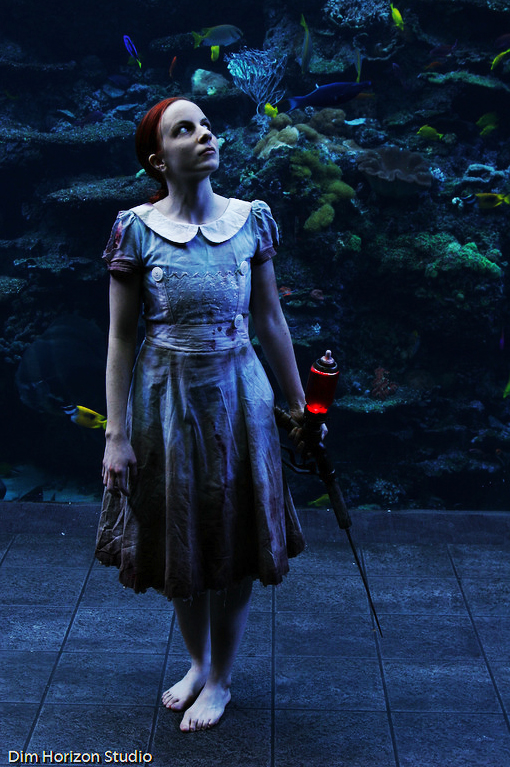
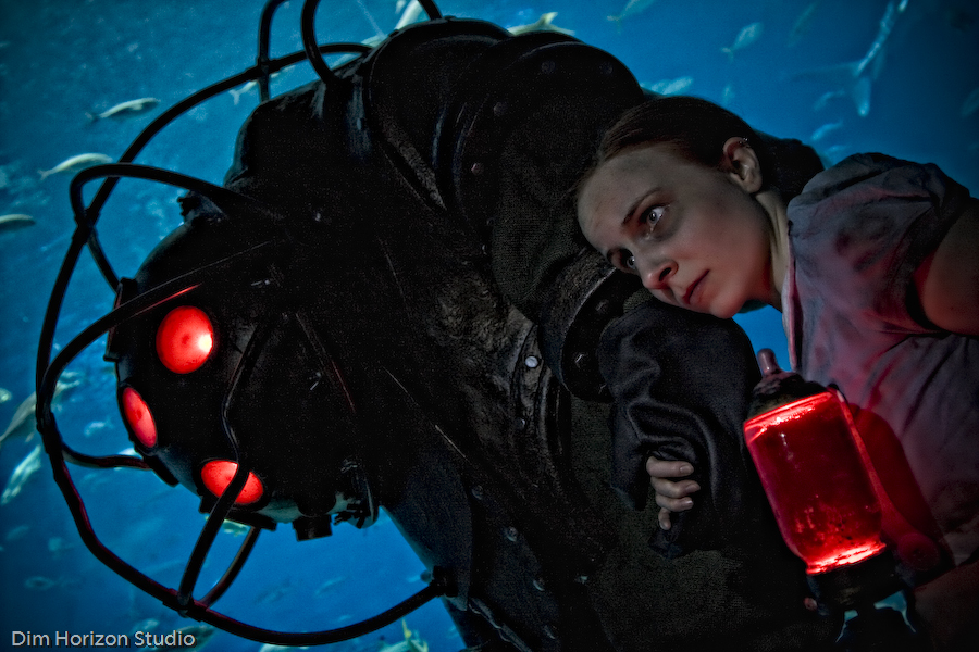
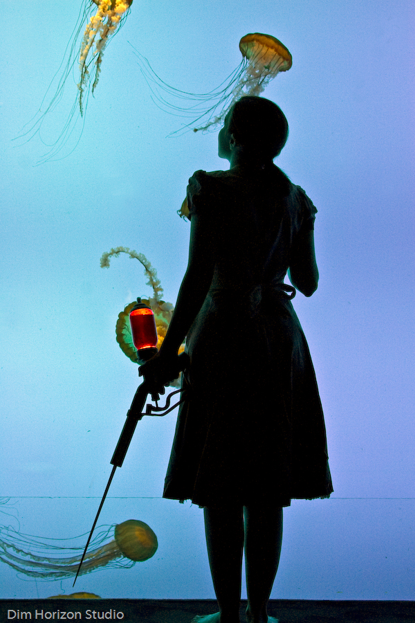
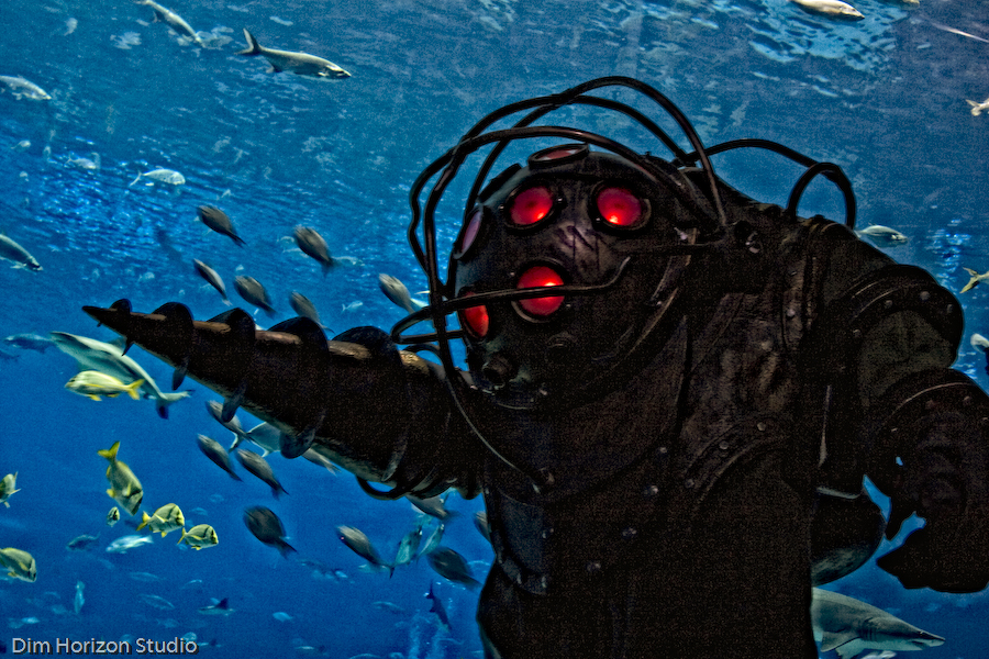
Aquarium Photoshoot!
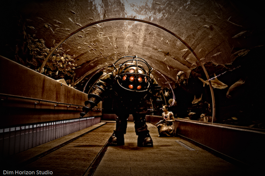
We did it! After two months of back-and-forth with the PR reps at the Georgia Aquarium, we were allowed to bring Big Daddy in for a photoshoot!
This was a colossal effort, and just like the original display of the piece, several hands went into making it happen. Much thanks to my friend Kim and Jay for getting up at 5am to come with us and be our handlers, to the Georgia Aquarium staff for this amazing opportunity, and to Matt Nicholson (and his fiancée!) of Dim Horizon Studio for doing such fantastic photography and editing.
I hope you guys enjoy these photos as much as I do.
Edit: 11.24.09 – Select wallpaper sized files now available for download!

For those interested, these pictures were taken in the “Ocean Voyager” and “Tropical Diver” sections of the Georgia Aquarium. They do offer private photoshoots for individuals and businesses, and they take place before business hours so you can have a crowd-free session. Our photoshoot took place between 8 and 10am, so we didn’t disturb the normal flow of customer traffic. If you want to contact the Georgia Aquarium about doing a private photoshoot of your own, check out this form.
There were divers cleaning the insides of the tanks when we first arrived, and as we began our shoot, some of them started to crowd around and look at what was taking place. Definitely an odd experience when you’re the one being looked at from the inside of the fish tank.
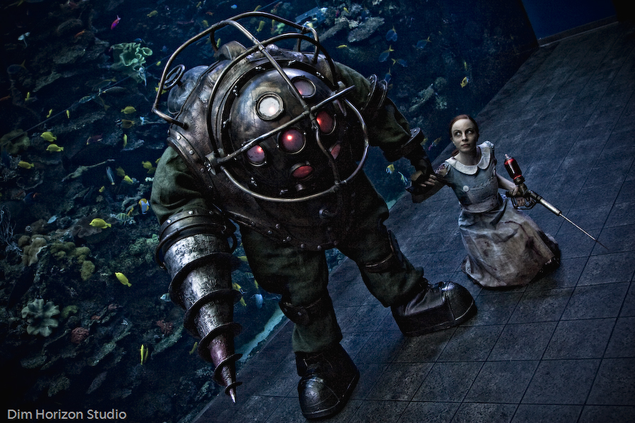


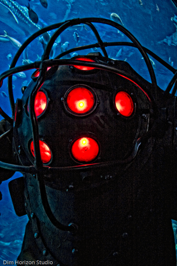
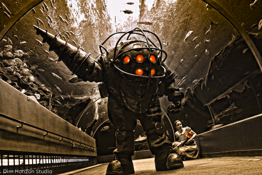
Its easy to see the biggest change in the suit: LEDs! I added light diffusion panels to the dome of the Big Daddy for this shoot, and I’m very glad I did. I also added foam padding around the shoulders, hips, and knees in order to fill out the suit a bit more and prevent that stick-like effect that showed up in some of the photography from DragonCon.
As with before, I owe all the sewing credit to my fiancée, Emily. She’s also the creepy-as-hell Little Sister in these shots.


Thanks for reading!

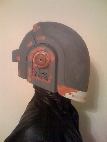
Daft Punk helmet, part 2
EDIT: For information regarding replicas of this prop, please see THIS POST
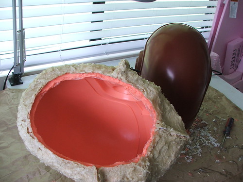
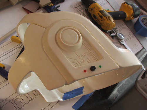
In the last post I had about this build, I ended with the finished master, ready for molding:
Silicone, silicone, silicone. Layered in stages, with registration keys and marks for the mother mold.
The mother mold was made with Plasti-paste. In retrospect, this makes for a very heavy mold that gives you some sore shoulders after slushcasting, and fiberglass may have been a better idea. At least its sturdy!

The detail captured in the silicone was perfect!
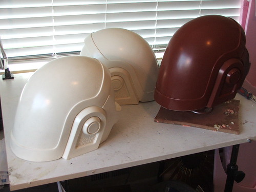
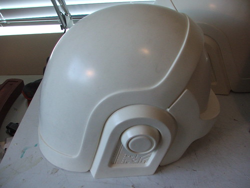
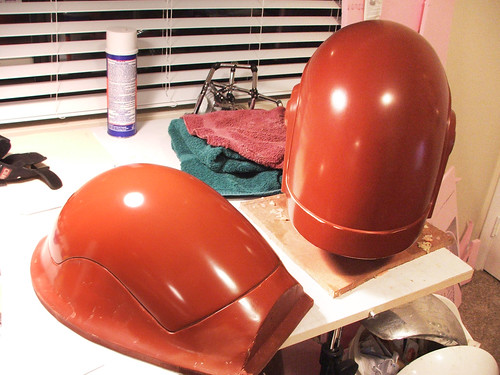
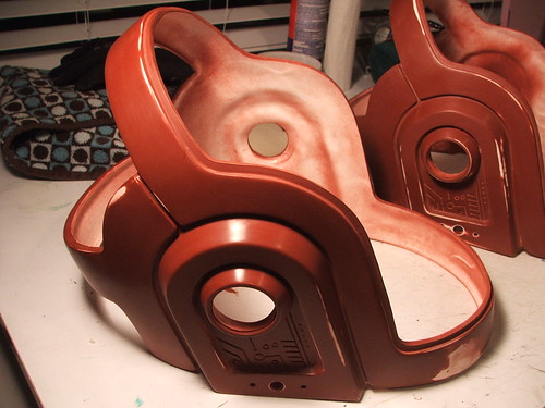
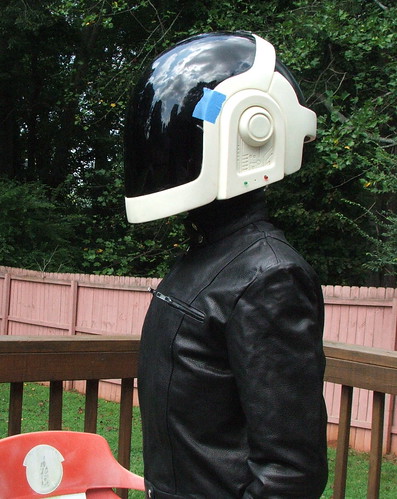
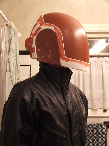
Some resin pulls. I started off with smoothcast 320, but it proved difficult to make a nice, thin pull. After switching to smoothcast 300, things got a bit more to my liking.
Couldn’t help walking around in one.

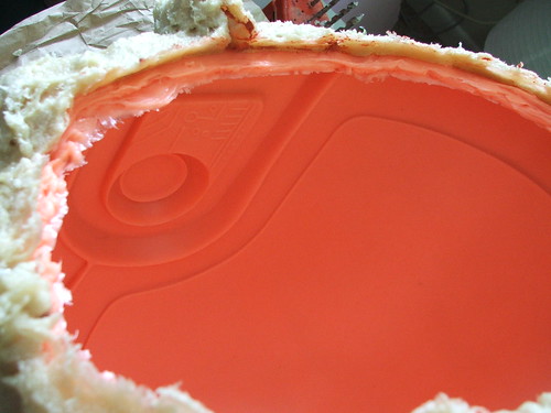
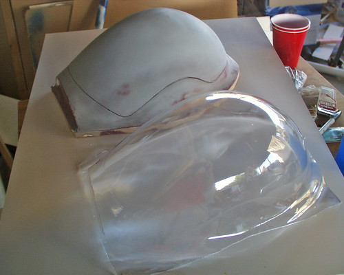
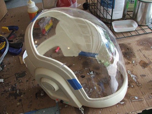
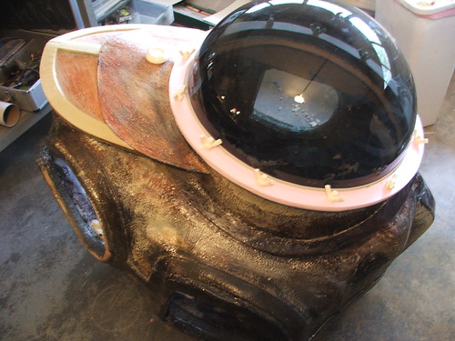
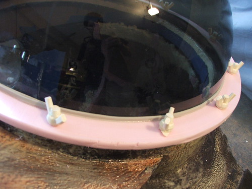
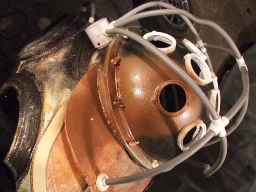
I trimmed out a casting of the visor to make the vacuum-former mold for the visors. This was mounted to a flat board so PETG plastic could be pulled over it.
Ear areas were trimmed out for the LEDs and black plate that sits in the cones.
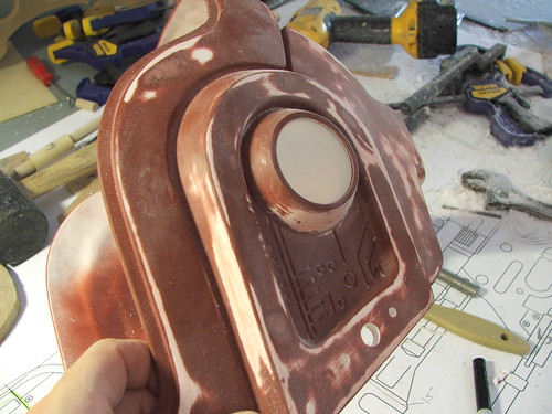
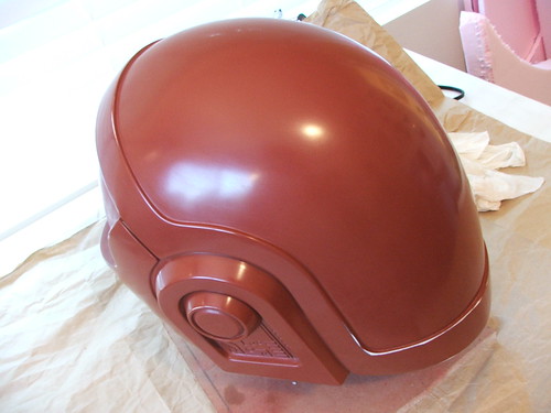
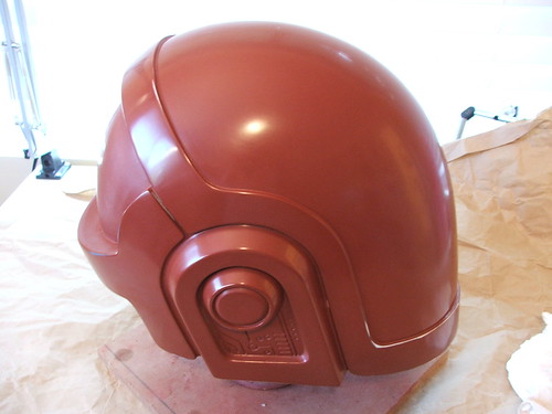
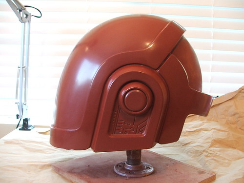
The trimmed and sanded helmets were given a coat of primer and wet sanded to take out any minor imperfections in the resin surface.
I need to take a minute aside here to go on a personal rant, and I apologize in advance for that because the last thing I want my blog to become is my own personal soapbox. This project is a large and complex one, and due to that there were certain things I had to farm out to other vendors and craftsmen. Specifically, the chrome gold plating of the resin and the vacuum-forming of the visors. I don’t possess the tooling to do either of these, so I had to look elsewhere.
Metalizing:
Initially, I had planned on going to M&M Metalizing for my gold chrome work. Over the phone estimates placed the process at $125 per helmet. I agreed, and sent two of the ones you see above (wetsanded and prepped) for finishing. The day after sending the package and an email confirming they were en route with tracking number, I received a phonecall from M&M. The price had risen to $175 per helmet, without much in the way of explanation. I was in a bind an under a deadline, and I agreed.
The day the package was arrived, I got another call saying that gold plating carried an additional $25 surcharge per part. This increased my original price of $250 for 2 helmets to now $400, plus return shipping. Angry, I requested they be shipped to another company for plating. M&M then charged me (COD with no invoice) $100 for 2-day return shipping. Next-day air had cost me $46 less than a week before.
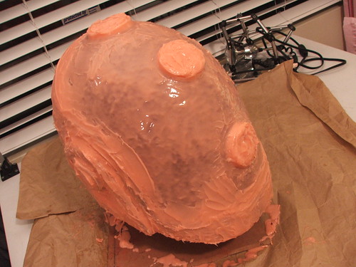
This is the condition the helmets arrived in at the other shop:
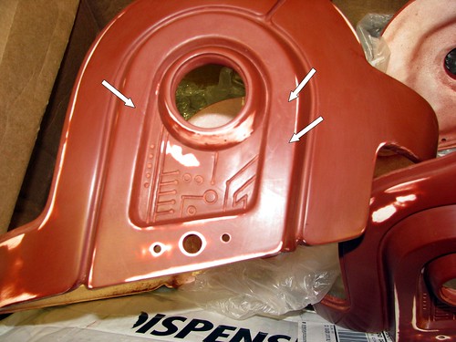
You can see the damage to certain areas noted by the arrows (larger version here) The helmets were not packaged in the box; merely thrown on top of the wrapping I had sent previously (they had been sent out by me wrapped very carefully in foam and bubble wrap to prevent the above from happening.) Additionally, the helmets themselves were greasy with fingerprints and other oils, which would have caused major imperfections in the finish.
I offer this story as an caution – and hopefully warnings like this will come infrequently – to anyone who reads these posts of mine looking for similar processes. As someone who relies very heavily on reputation in order to have a continued supply of business, I don’t see how anyone can operate in this manner. My contact there was generally abrasive on the phone, and obviously cared very little for my continued patronage.
Vacuum-forming:
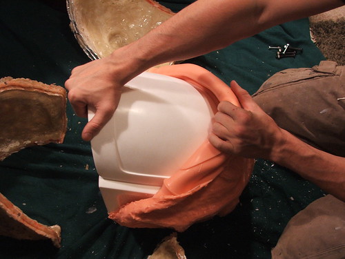
Mike (BlindSquirrel), a fellow prop builder over at My Dumb Projects, took care of the vac-forming for me. Mike is a fantastic guy, an amazing craftsman, and his work on this project well exceeded my expectations. Actually, his patience was the best part, as my mold proved to be a frustrating piece of kit to work with (mostly because I didn’t know how to build a proper vacuum-former mold) Eventually he worked out the kinks, with stellar results:
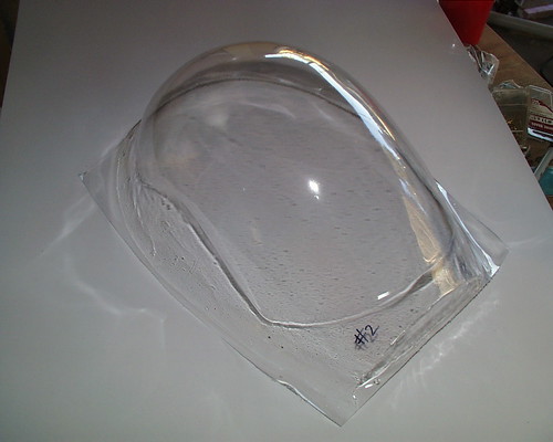
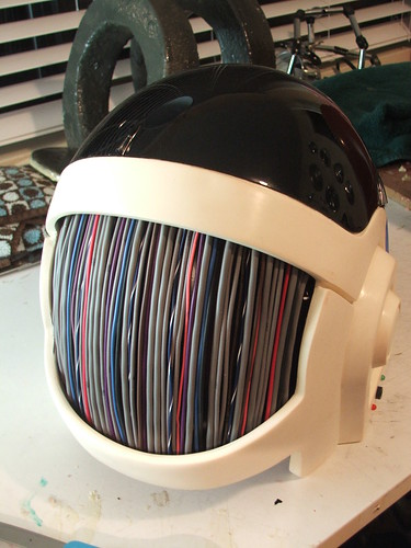
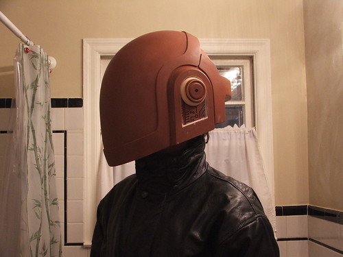
The visor was tinted on the inside with car tail-light paint, called “VHT Nightshades” The result is a nearly opaque outer appearance, but only a tinting similar to dark sunglasses from the inside. This visor, like the rest of the helmet in this post, is a test piece. You’ll notice some webbing in the PET plastic in the images. No sense testing the tint on a shiny, perfect piece!

The back wire “hair” is a test piece for now, built with pieces I have laying about from other various projects. The actual plastic dome is built from the excess resin used trimmed out of the visor area. Currently the colors are incorrect, but this is just a “proof of theory” piece.
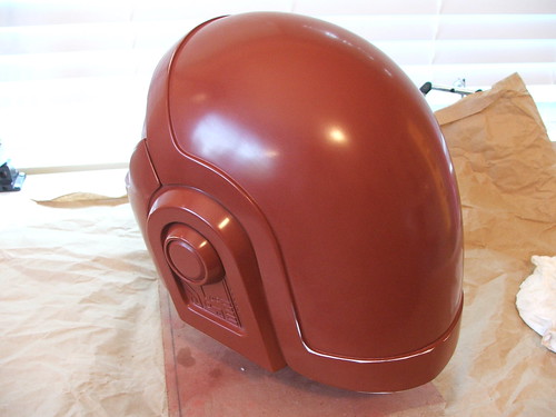
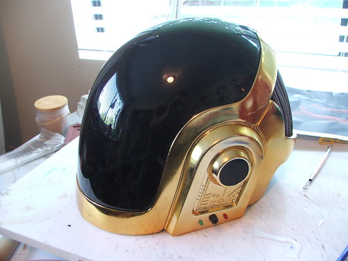
New Chrome!
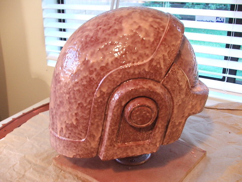
The gold plating done in these shots was completed by “E7 Technologies” and is a process called Cosmichrome. While we’re still getting some small issues worked out, this is a very cool technique. The people at E7 are everything that M&M are not. They have helped me and been very accommodating through the entire process, and have been willing to run test pieces for me in order to achieve the best result. The images below are a shot of the “dud” helmet, which had too much orangepeel and issues with the finish to be called a success.


Neat video of the chroming process:
Part three should be the final chapter in this build, with everything coming together. Look for it around Halloween!
Still to come….

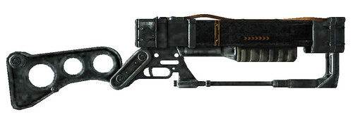
Fallout 3 AER9 Laser Rifle
EDIT: I’m currently working on a bit of a redesign here. Apologies of the site looks like crap for a little while.
A commission came to me very, very last minute for a good friend of mine. He was planning on doing a Vault Dweller costume from Fallout 3, and needed a weapon in a month. Unfortunately I had other commissions, deadlines, and large projects to finish in that span of time. I looked at my schedule, decided I could shave off some sleep, and promised him 30 hours of build time. What follows is the result of that hurried errand.
First, as always, I put together some blueprints.
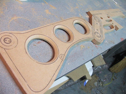
In order to save time, my friend came over and traced my blueprints onto MDF. I taught him how to use a bandsaw (nothing like a crash course in something that can leave you fingerless!) and he went to town rough-cutting the shapes I’d refine later into the gun. Here’s where we started:
Impressive, right? I had a sick idea of just scotch-taping all these together, painting the whole thing silver, and handing it to him the day of the convention… but I’m not that mean. Ignore the lighter pieces near the bottom – those are part of another build.
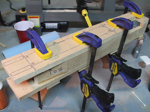
After cleaning up the cuts on a belt sander, I began the assembly of the main body in the 2 most prominent parts – the square “barrel” and the rear stock. These are both made from 1/2″ MDF. The barrel has a few sections cut out for the microfusion cell…
…and a space for the rear stock and lower receiver to mount

I used a table router to re-shape the holes in the stock and bevel the edges. This was also a low-budget build, so I didn’t have the liberty of going out and buying fancy new holesaws.
The lower support rod was made out of varying sized of pine dowel, threaded over a 1/4″ aluminum bar.
The front grip was made from 2 pieces of 3/4″ MDF, screwed together and shaped on a belt sander. Styrene will eventually make up the grip texture.
The microfusion cell was pieced together from some pre-existing elements. I had a small dome mold that I’m using on another project that happened to be pretty close. I pulled two of these and epoxied them around some 2″ PVC pipe. MDF discs were affixed to the main body to make the housing around the cell.

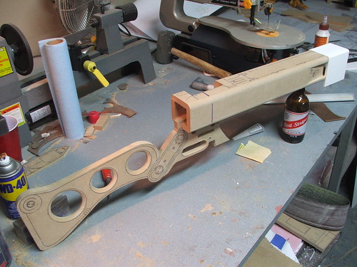
At this point, it started to resemble the final product! This is about 6 hours into the build (Yes, I’m using “build” as a noun! Colloquial English; take that grammar sticklers!)
Styrene was added to the lower grip, as well as the cell eject lever and front barrel area for the raised textures

The upper barrel pipe was made out of 3/8″ steel pipe. This terminates into a lathed pine dowel glued to the barrel corner
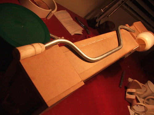
If you’re wondering why some of these shots are so dark, recall that the “extra time” I found to build this came when I should have been sleeping. The bulk of this project was done between 10pm and 1am on most days…
After a coat of primer and some sanding, I started scribing panel lines with a dremel tool, and adding screw recesses around the front of the barrel.
Other details were added in MDF around the cell loading chamber, and the rear part of this area was faired down into the barrel of the gun with apoxie sculpt. I also added the raised pucks on the grip and stock.
Recessed areas were drilled into the gun and filled with countersunk phillips screws
More styrene and MDF pieces were added to the barrel and rear area of the gun to build up the details in these areas. The shapes of these were largely improvised, as by this point I only had 4 days left until my deadline with many other projects that needed completing.
After this, the whole gun received a coat of gray primer to seal the remaining exposed wood.

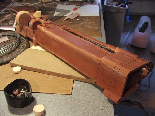
The first coat of paint went on shortly after the above finished drying. I used Krylon hammered silver, followed by a coat of Testor’s Olive Drab on the main barrel.
Fortunately for me, these guns are supposed to be 200+ years old in the Fallout 3 universe. That means its time for my favorite thing of all… heavy weathering!
The basecoat of weathering was done with acrylic paints and matte gel medium. I did an initial coat of black, followed by browns and greens to simulate dirt and corrosion.
After this dried, I gave the whole piece drybrush silver accents to simulate wear and tear from the wastelands. chipping away at the paint and caked-on dirt. The finished piece has a nice shimmer to the metallic silver drybrush, which simulates metal rather well.
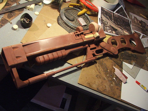
Finally, some more shots of the finished product from a few different angles. I’m still looking for a good way to transfer my vector decals to the gun. I tried water-slide as with my Portal gun build, but yellow ink on top of dark green showed up very poorly. There are a lot of details missing from the final product, so I want to return to this prop someday and build it without such an insane time restriction!
I really wish I could have given this project a bit more time and been more dedicated to the intricate detail this gun has, but for a 4 day build this turned out better than I could have hoped.
Happy Super Mutant Hunting!
Wait.
…you know… I had this whole thing written out, and then I went to preview the blog entry, and something just didn’t look right. The rifle was weathered, but it still looked too clean on that white background. The graphics of the Fallout games do a good job of making the weapons look blackened, but I felt like this needed a bit more.
I went back after thinking about it, and decided to add some rust to the AER9. The shots above is how the gun was delivered and shown at the convention. Here’s how it sits now:
And, just for the hell of it, a modified version of one shot in the “Fallout 3” graphic style:

(Higher res pic HERE, and more high-res shots of the build process available on my flickr page)
Ok, NOW we’re done!

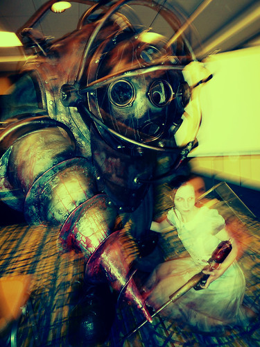
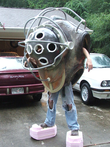
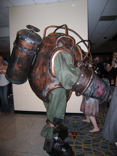
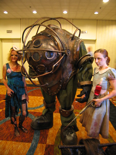
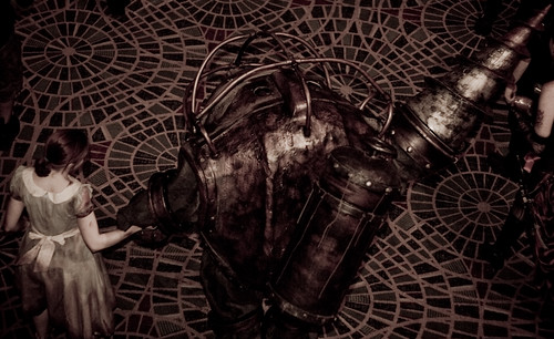
Big Daddy (Bioshock)
I finally lost my mind enough to try to tackle one of these big guys. For those unfamiliar, Big Daddys are the protectors of the Little Sisters in Rapture, an underwater city devoid of morality which has degenerated into chaos and insanity. They are huge, fast, strong, and as it turns out, a solid pain in the ass to build.
I’m going to break with tradition for a sec, and show you the finished product first. This is a long, long, long post that details nearly 7 solid weeks of work, and you guys deserve to know that the long post is quite necessary, and (I think) well worth the read.
Credit goes to “scenemissingmagazine” on Flickr for this amazing photograph:
So, here’s how I did it.
First thing’s first, I needed blueprints. I built these in Illustrator, based off some very good reference images that the guys at 2K published in their artbooks:
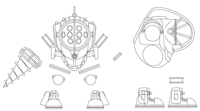
Since this is such a large project, I’ll break down the build process into partitions: The main body, the dome, the drill arm, the dome cage, other details, and the final paintwork.
The Main Body
Starting with the blueprints printed at full scale (HUGE) I made cross sections out of insulation foam and glued them into place. The empty areas between sections were filled with cardboard. This formed what I called the “skeleton” of the body.
The empty cavities in the skeleton were then filled in with expanding foam
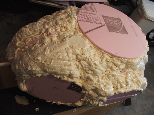
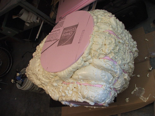
After drying, the foam was carved into the shape of the main body
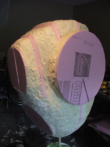
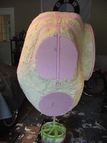
After this was completed (and the foam given more drying time so it would retain its shape) the entire form was covered in stretch fabric. This smoothed out a lot of the lumpiness of the foam
Accent areas around the arms, legs, and top of the body were made out of insulation foam, then glued to the body. Before coating with paint or fiberglass resin, these were covered with Ureshell to prevent the poly foam from dissolving. Certain areas on the body itself were also given a coat of Ureshell so they would not disintegrate. (In retrospect, I’d recommend Smooth-On’s “Shell Shock” resin over Ureshell – it’s faster curing, non-flexible, cheaper, and easier to work with.) After this was dry, the entire body piece was given several applications of fiberglass resin.
The front flap was added using more insulation foam, and also given a coat of Ureshell and resin. After this was dry, I began hollowing out the foam and cardboard.
After adding some details on the body with foam tape, more ureshell, and more resin, I had a finished form!
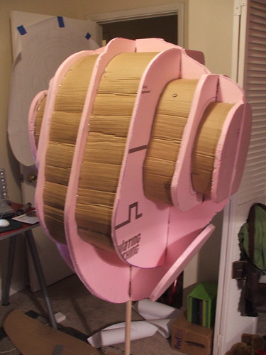
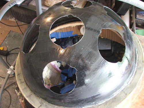
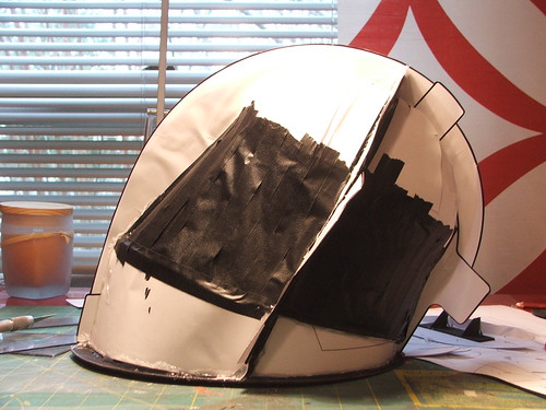
The Dome
I started with a 24″ smoked security camera dome off of eBay. This came from a demolished shopping center, and are actually hard to track down these days, given the much smaller size of most security cameras. I remember these all over the place as a kid.
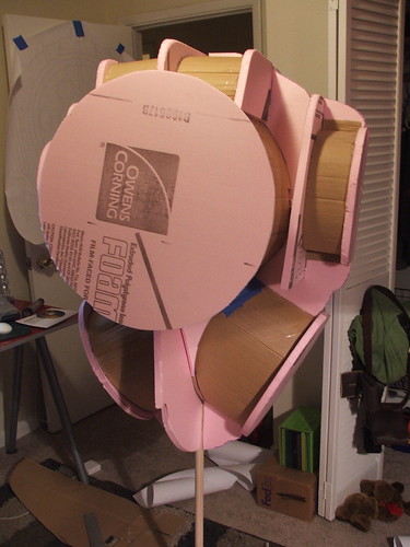
After trimming the square edge off, I cut a disc from insulation foam to serve as the “ring” around the dome.
I made resin copies of wingnuts which were glued into place on the trim ring. About 15 of these resin duplicates weighed as much as a single wingnut. Since I had to wear this thing, every ounce saved counted!
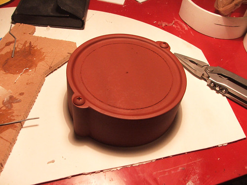
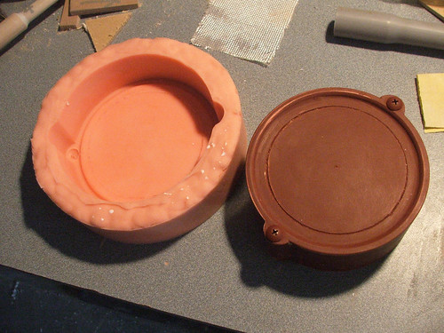
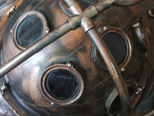
For the portholes, I made a single master out of PVC and MDF wood…
…which I molded in silicone. The portholes were all slush-cast to save weight and time in production. Also, this way, they’re completely identical.
The tape here is marking the spacing of the portholes
After coating the dome in resin to thicken it a bit, I trimmed the porthole-holes with a dremel. The dome was a very brittle acrylic, so this was a nerve-wracking process!
The drill arm
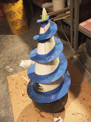
Unfortunately, since this project was done in such a hurry, my process photography was somewhat lacking. The drill started out as an aluminum rod with 4 triangles of matteboard affixed to it. Rings of foam were made around the matteboard, then paper layered on top of that to create the cone shape. The actual “blade” of the drill bit is made from masking tape which has been layered in small sections to follow the curve of the drill sides.
This piece was coated in several layers of fiberglass resin (some with tinting to check coverage)
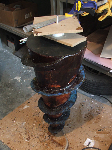
To create a really worn look, I added bits of debris to the fiberglass resin. This made a convincing textured metal finish in the end, as these parts were painted to look like rust, dents, and bits of splicer.
A PVC cage and old DeWalt 12V cordless drill make up the support frame and motor for the drill. I moved the battery inside the body of the suit to save on weight hanging from my arms.
The “housing” for this mechanism was made from a concrete tube, electrical conduit PVC and more foam tape. This was painted in ureshell to protect it during painting as well as to give it texture.
The Dome Cage
This was constructed mainly out of PVC electrical conduit. This pipe is gray in color and takes heat and bending much better than standard white PVC tubing. I bought 40 feet of it for this project and ended up using about 35. At only ¢88/10 feet though, this was an easy buy.
The sides terminate into 3″ PVC couplers. These slide over 3″ PVC pipe anchored to the body that has been notched to be a sightly smaller diameter than 3″. Since the wearer has to enter through the front porthole, the dome as well as the cage must be removable. The front of the cage is friction-fit at the top and bottom anchorpoints, as well as the sides, so it can easily be put on and taken off.
A quick test of the body, dome, and cage. This is after the dome has had all portholes carved out and secured.
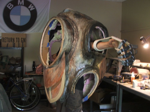
Other Details
An animatronic hand and arm extension were created for the left side of the suit. This would help prevent the “stubby arm” look I’ve seen on other Big Daddy suit builds
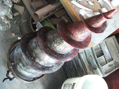
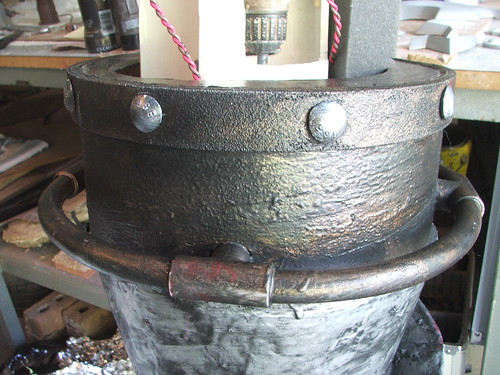
The rear tank was made from a 12″ concrete tube with foam plugs on the top and bottom carved to a dome shape. The bands around the tank were made with foam tape coated in Ureshell.
I made a pushmold of some bolt heads for texture, these were cast in resin and added to the tank as well as the banding on the main body.
Boltheads and a first coat of paint on the tank. The wheel at the top is a cake decoration from our local supermarket.
The boots were made from more insulation foam. These give me about 6″ of lift and make the feet look proportional to the rest of Big Daddy. I got this idea from a guy named “Duck” on the Replica Props Forum. Thanks Duck!
Painting, Weathering, and Details
Again, I apologize for my shoddy progress shots. Trying to get everything ready for Dragon*Con in time, I neglected my camera a lot.
These are the discs that go over the arms and legs. I don’t have any shots handy of their creation, but they were made from layered pink foam, more Ureshell, and resin cast bolt heads. The first shot shows a raw bronze painted piece next to a completed weathered one.
The initial painting was done with hammered paint in silver and copper.
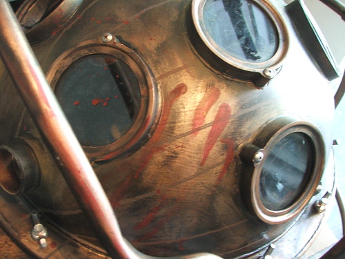
Over this went a dusting of 99¢ flat-black el-cheapo paint which was wiped off as it dried. Resin cast faux-bolts were also added to the main body as well as the drill arm before painting.
Additional weathering was done with acrylic paints, gouache, and iron powder to simulate rust. Bolt heads were touched up with silver paint so they would accent the brass better. The PET plastic in the portholes was also weathered to look grimy. After all of the above had dried, blood accents were added.
This bit of blood is my favorite part of all the weathering on the entire costume. Its details like that that I think really make the effect work.
The drill was weathered in the same manner
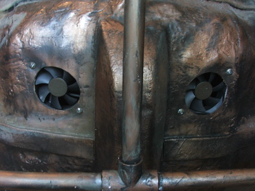
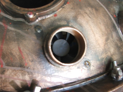
Finally, four 3″ computer case fans were added to the body and dome in order to keep the heat down. Two of these reside in the top of the suit, while the other two live in the bottom 2 ports on the dome.
Finished Result!
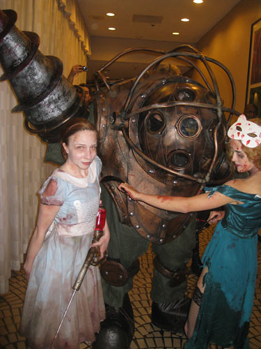
Since I was wearing the finished suit at Dragon*Con 2009, I don’t have any pictures of my own to show! Instead, I hope the owners of these respective photographs (credited here) don’t mind me showing them off a bit. My “Little Sister” is my Fiancee, Emily Keith. Our “Baby Jane Splicer” is our friend Mandie Reese.
From “mcmullets” on Flickr:
From “RJDaae” on Flickr:
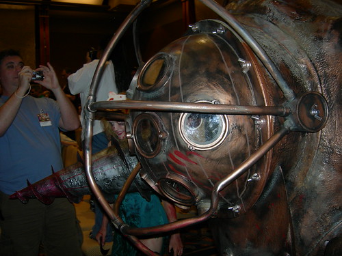

From “Hueyatl” on Flickr (note, I had taken the drill arm off at this point to make walking and navigating easier)

From “Sarcasm-hime” on Flickr
A neat video of the drill working on YouTube while we were posing for the Friday Night Costume Contest photos:
And, last but totally not least, my favorite shots of all:
From “phr3qu3ncy” on Flickr:
From “scenemissingmagazine” on Flickr, a second time just because I love it so much:
This build and the execution of wearing it was more of a group effort than anything I have ever tackled before. While I did the construction of the prop myself, I did have a number of people assisting me in handling the costume during the convention itself. Emily, Mandie and I won “Best Journeyman” as well as “Best Professional Design” at Dragon*Con for this suit as well as for their costumes.
I’d like to thank my friends Ryan Shelor and Becky White for being my handlers at the convention, as well as my friend Jay (last name omitted at his request) for his build assistance during my last-minute frantic hours. I should also add that all sewing and cloth work was completed by my fiancée Emily. I cannot sew a straight line to save my life. I’d also like to thank all the random people at DragonCon (Security, Hotel Staff, etc) who assisted in helping me get around the convention while wearing this. Lastly, much thanks to the random guy who gave me a fresh, cold 12oz can of Red Stripe after our group won at the Masquerade. A celebratory beer never tasted so good.
EDIT: The suit weighs, in total, between 50 and 60 pounds. This includes all ancillary details like the drill arm, necessary batteries, shoes, etc. I was able to wear it for extended periods of time if the arms were disconnected and I was not walking. With the arms connected, I could stay in one spot for 30 minutes or so “comfortably.” Walking outside in the Atlanta heat bordered on suicide.
EDIT 2: This costume is not 100% completed as of yet. I wanted to share the work after DragonCon, and I will update again when the suit is finished to my standards. Unfortunately, the clock was against me on this and some of the details suffered because of it.
I have plans to add padding to the arms and legs in order to fill them out more. Also, LEDs will be added to the front dome to simulate the red and yellow glow of the Big Daddys. The suit did suffer some minor damage at the convention (nicks and scrapes mostly. Have you ever tried getting a Big Daddy into a hotel elevator??) so there need to be some small repairs as well. For those wondering, the suit was supported by a hiking backpack mounted at 6 anchorpoints inside the main body. I felt terrible carving up a perfectly good backpack, but the end result was worth it. Further, I am a small guy! 5’7″ tall and 135lb soaking wet. I’m sure someone of greater stature than I could hold out much longer under the weight of a costume like this, but muscle training just wasn’t a part of the schedule. Maybe next time!
EDIT 3: The drill does spin correctly, pulling material forwards and into the bit. It looks weird in the YouTube video, but trust me on this! It also has the ability to spin much faster, albeit at the expense of my elbow joint. I tried not to spool it up to full speed too much in case something went awry (I didn’t want it disintegrating into an audience or expensive camera equipment)
Emily and I are currently interested in doing a photoshoot in Atlanta with this suit and her Little Sister costume. We’d love to see about getting into the Georgia Aquarium if possible. Any chance there is someone out there that can make some calls and pull some strings?
All of the products listed in this write up are the products that I used and can recommend. Some of them are provided as Amazon affiliate links, which help support Volpin Props.

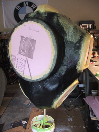
Daft Punk helmet, part 1
EDIT: For information regarding replicas of this prop, please see THIS POST
Guy-Manuel de Homem-Christo is one-half of the french techno group Daft Punk. I was commissioned to make a replica of his iconic gold helmet:

Based off a lot of research images I put together a rendering of the helmet in portrait and profile view, then mounted scaled printouts of these drawings to illustration board. There’s a really talented guy named “Featherweight” that makes a variety of props out of cardboard; this was adapted from one of his tutorials:
I know its not much, but bear with me…
I took this and covered the model in expanding foam…
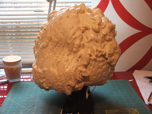
…which was then carved into a rough shape:
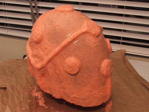
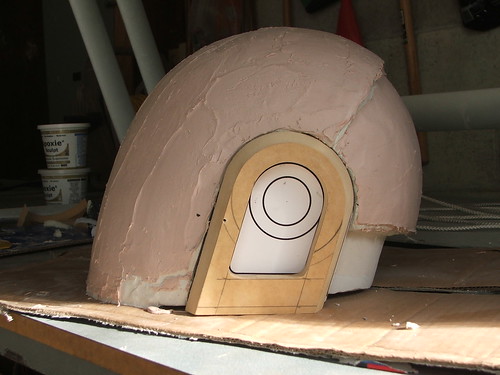
This was the coated in air-drying clay and apoxie sculpt to give me the general shape of the helmet.
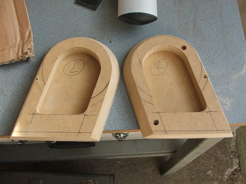
Ear areas were cut out with a jigsaw to make space for the “D” shaped ear pieces in the helmet:

These ear pieces were cut from MDF and beveled on a router, then mounted into the helmet.
Then came the spot putty

…and the bondo…
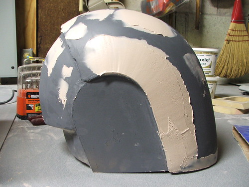
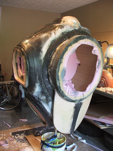
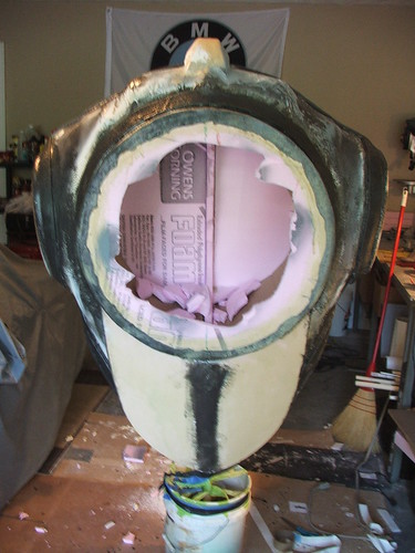
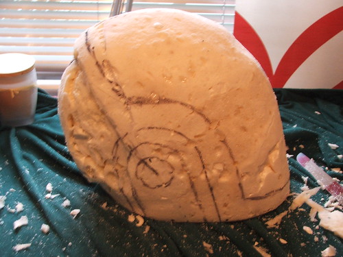
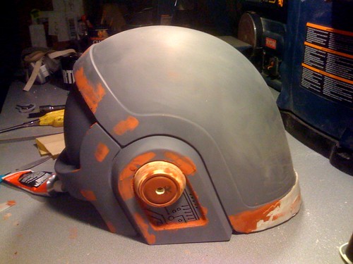
I repeated the above steps (A LOT!) until I was satisfied with the curve of the visor area. After that was defined, I added foam and apoxie sculpt around the hemlet to build up the upper and rear “hoop” areas, as well as the “chin.” I’m kind of making up the terms for this as I go, sorry if it gets a bit confusing.
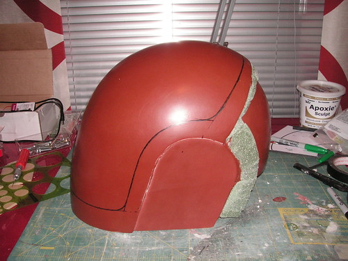
In case anyone is interested, I alternate primer colors when building very smooth props so I can see how far down I’m sanding when I revise the shape of things.
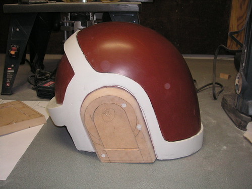
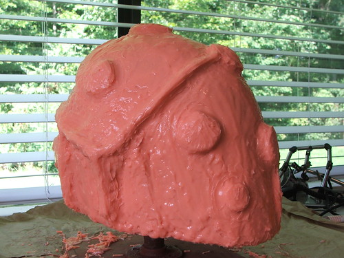
Guy’s helmet has a sort of circuit board pattern in the ears, topped off with a beveled “puck” that sits above it in the upper circle area of the ear hoop. I had a local trophy shop laser-cut this circuit board pattern into some 1/2″ poplar, which I trimmed and inserted in the ears.
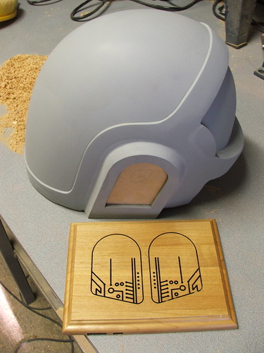
After installing these, I trimmed the lines around the ears and behind the rear hoop with a dremel tool:
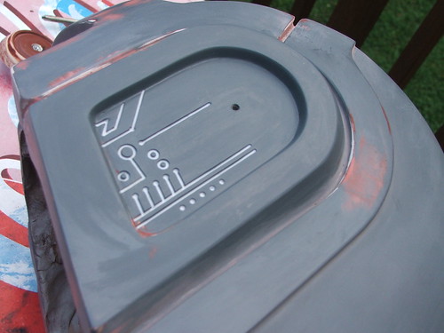
Based off some really good reference shots posted on the RPF, I noticed these patterns were cut far too deep. I filled the cavities with resin to level them out a bit:
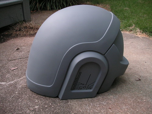
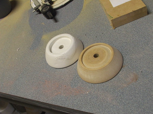
Shown here is one of the ear “pucks” next to a failed test. The one I went with is a MDF piece shaped on a lathe. The one in the background was sculpted out of foam, and couldn’t hold detail as well. I ended up molding the MDF one and pulling 2 resin copies of it.
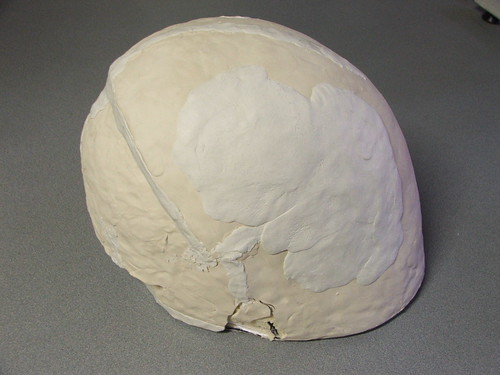
Then, there was more spot putty to fill ever smaller and more minor imperfections. This helmet will eventually be vacuum-metalized in gold chrome, so it needs to be perfect.
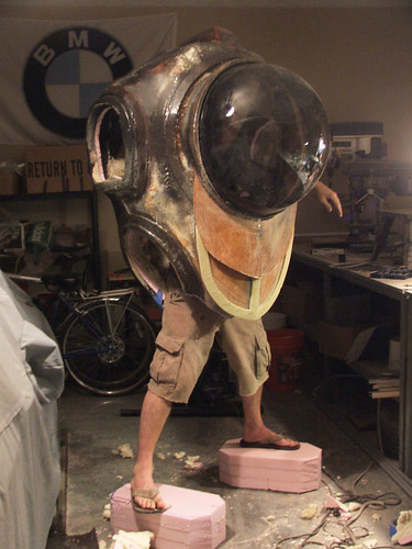
The advantage of making the helmet the way I did meant that I could try it on over and over again during the course of the build. I couldn’t see anything, but it looked cool nonetheless!
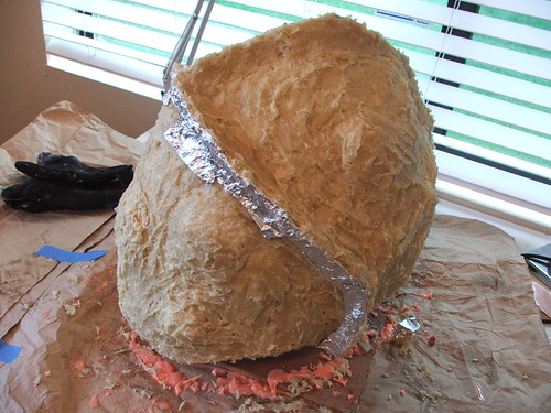
Finally, after some harrowing antics including one late-night trauma where the sculpt was knocked off my workbench, the master was finished and ready for molding. This piece has been wet sanded with 2,000 grit paper and buffed with turtle wax in preparation for molding. Can’t wait to pull the resin copies!
Next up is resin casting, electronics, and gold plating… not to mention vacuum-formed visors done by a fellow prop maker friend. Stay tuned!

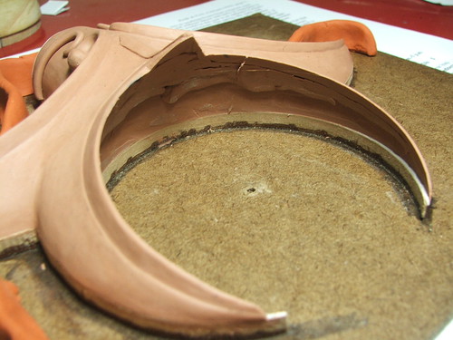
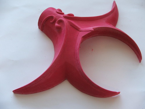
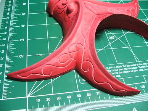
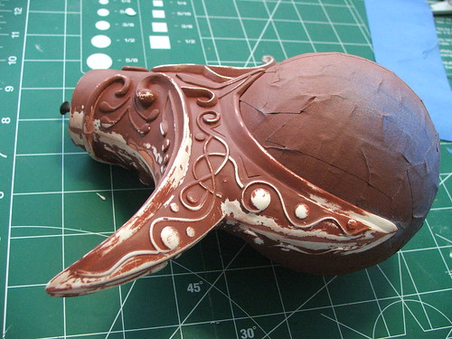
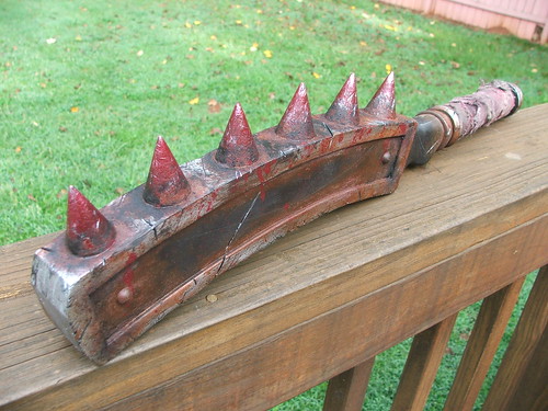
Kraken Club revisited
Normally I don’t think I’d make a post about reproducing the same prop I’ve already shown, but I REALLY liked the weathering on this one, so I decided I’d share.
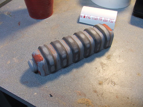
After doing numerous copies of the original club, I got an order for a more interpretive piece. According to the canon in Final Fantasy XI, there are monsters that wield similar weapons to the ones players can use. One group resides on an icy island and has been marooned there for 2 in-game decades. My client wanted to see a club with 20 years of abuse and neglect showing.
For comparison, here are duplicates #4 and 5 of my original club:

And now the more “traveled” version:

A painter friend of mine showed me some advanced weathering and texture techniques involving iron powder and water-based paint, which means this resin club actually rusts!

Check out higher-resolution pics at my flickr account!