
Planet Express Ship, Futurama (part 1)
This is going to be a 2-parter, since the total mass of the entire build log would be enough to crush most RSS readers. I’ve been told I can be a bit long winded when summarizing my process, but I prefer to think of it as “thorough.”
From my previous Holophonor build you might guess I’m a bit of a Futurama fan. When I work in my shop, I typically prefer to stream videos instead of listening to music. For some reason it occupies my brain enough so that I don’t get distracted. I can’t explain it, but the point of this bit of background is that I’ve gone through the entire series of Futurama a couple of dozen times while in my shop. I’ve never scratchbuilt a model ship before, so ol’ Bessie seemed like a great place to start.
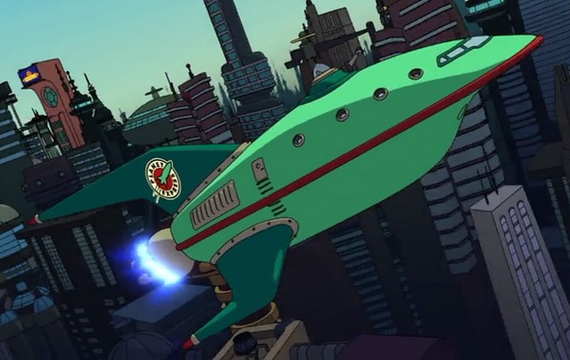
I grabbed a TON of screenshots courtesy of Netflix and got to work making a set of blueprints.
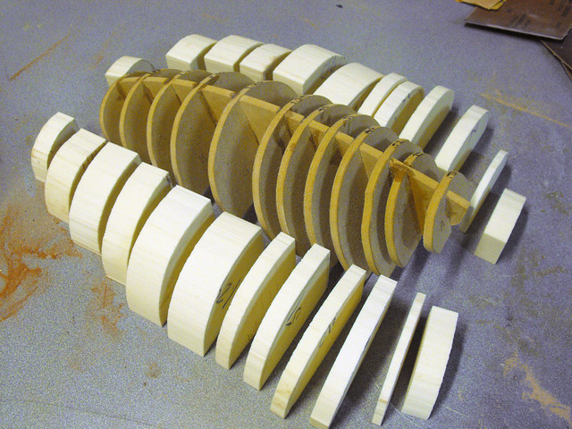
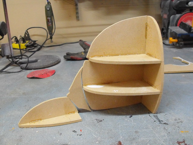
These were then transferred to 1/4″ thick MDF to create a series of spines, and the cavities in the form were filled with urethane foam blocks.


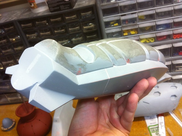
Then there was a bunch of shaving and smoothing and dust, starting with a rasp and moving through 50 grit sandpaper, followed by 80, 120 and 220. This gave me a pretty solid foundation. I also trimmed the fins out of some 1/2″ MDF blocks.


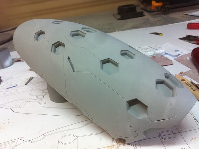
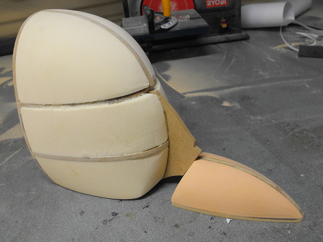
Divots on the body were smoothed out with passes of bondo and filler putty until the little bullet shape was to my liking.

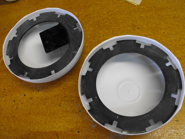
In order to create recesses for the assemblies on the belly of the ship (landing struts and staircase) I vac formed a few MDF blocks and used the negative plastic shape as the recessed form.

Pictures might explain the rest of this process better. Here’s the rear strut cavities:


And the forward landing skid stairwell:


The center cargo bay door area was done in a similar manner, using .060″ styrene to form a box for the inset area.


These doors won’t open, instead they’ll eventually be an access door to the interior electronics held on with magnets. The plug for the inset door was made from more urethane foam and styrene spacers to simulate a door seam.


Back to the fins – mostly the shaping was done with a dremel by hand, then the MDF forms were skinned in resin to give them a bit of strength.

I made a quick mold of the side fin in order to pull a couple resin copies for the left and right wings. There would be a bit if customizing done later on but the base shapes would be nearly identical.


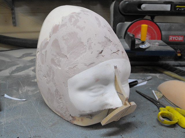
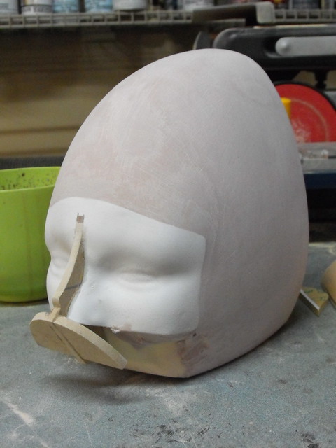
In order to make the lip around the base of each wing/fin fit flush with the body of the ship, I sculpted them directly on the ship itself. First I laid down a strip of masking tape and waxed the surface with automotive wax. After this hardened, I super glued the fin to the tape itself. The glue will still bond lightly despite the wax, enough for the purposes I’m using it for anyway.

The lip on the fin was sculpted with Apoxie Sculpt. After this cured I was able to pop the fin loose from the masking tape because of the wax laid down earlier, and any left over material was easily cleaned off the ship body by removing the tape. I repeated this process for the back wings as well.


To make assembly easier later on, I added some large tabs to the fins and corresponding slots to the ship body. The process here is largely similar to the insert for the bay doors mentioned earlier.


Unfortunately a few rough assemblies made me realize the rear wings were way too stubby. I ended up chopping them in half and adding a 5/8″ spacer to each fin to stretch them out a bit. Blending these shapes back together took way, way more time than I anticipated, but the results are worth the effort.


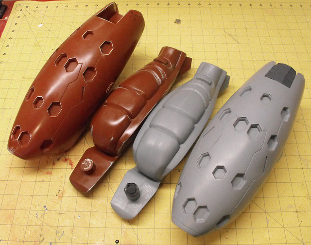
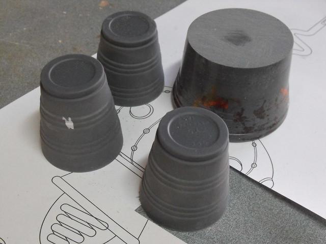
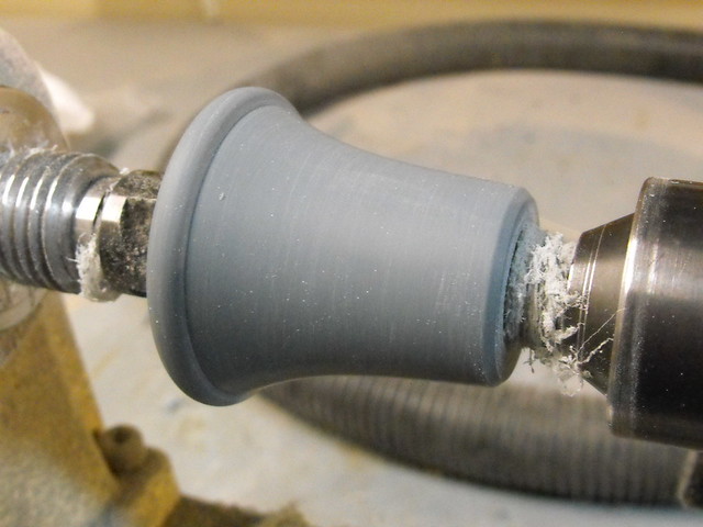
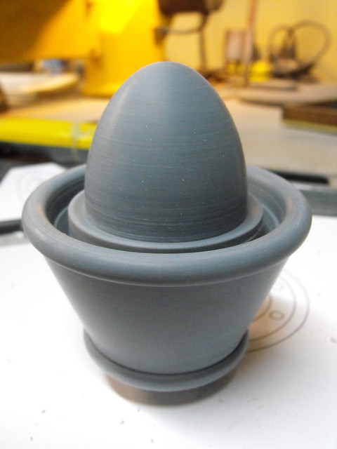
Growing a bit tired of sanding, I fired up the lathe to turn out some of the round parts. These include the landing struts, landing feet, turret, barrel and window port hole. All of these are turned from urethane resin (ONYX for the black parts and 320 for the pink barrel and white port hole) – ONYX tends to turn very harshly and will chip easily. 320 is smoother but will chatter if you try to trim off small amounts with anything but an extremely sharp chisel.


I used my laser cutter and a bajillion pieces of styrene and acrylic to make the front landing skid staircase. It was when I made this part that I realized the scale of my ship would be a nice, round 1:50.


The mounting frame for the stairs was also cut from acrylic, while the curved base is a piece of hand-shaped heated sintra.

Back to the main body! The base for the turret was made with apoxie sculpt, and a negative impression of the turret itself was made to ensure a proper fit using the “bondo squish method”


Finding half round trim nearly 3/8″ wide proved somewhat difficult, so I used some PVC rod cut in half lengthwise for the red bumper around the midsection of the ship. This was heated in sections and glued to the perimeter. Any gaps were later blended in with filler putty (U-POL Dolphin Glaze, in this case)


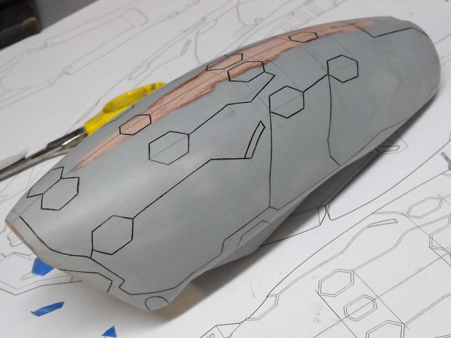
After molding the single port hole and making 8 copies, I set about recessing them into the body of the ship. They don’t seem to have a standard amount of distance between them, though I’m sure there’s a formula that can explain the incremental increase of space between each window. These were etched into the body then carved out by hand with a dremel before inserting the porthole castings.


More accents and details followed! Starting with the vents & door on the rear of the ship: I initially planned on cutting styrene and simply heating it to shape onto the ship body. This didn’t work, as the precisely cut shape warped and stretched as I laid it over the curve on the rear of the fuselage, resulting in a lumpy mess.
My solution was to cut a shape in masking tape first, and lay it on the ship in the desired location of the vent plate. I then took a larger sheet of .040″ styrene , heated it, and layered it over the taped section.


Doing this actually left a very thin impression on the inside of the styrene which I could use to trim out my curved form. In order to make sure everything was as straight and even as I could make it, I cut a mirrored piece of tape and laid it over this faint impression to use as a guide when cutting.


Small pieces of quarter round styrene bar were cut to shape and rounded over on their edges to make the individual vents. This. Took. Forever.

The process for the windscreen was largely the same, though I did spend a lot of time tweaking the initial masking tape overlay to make sure it had the right shape when viewed at various angles. half round styrene bar stock was used to make the trim, and the gaps were filled and sanded with green modeling putty.

Adding rivets to the fin trim rings started out simple. I planned on using small scrapbooking ornaments to simulate these, but after getting all of them secured they just seemed too flat and too small. Off they went, and in their places I used the heads from straightpins instead. Much better.


Couldn’t resist taking her for a spin. WOOOSHHHH….

Oh wait. The engines.
The main form was shaped in the same manner as the main hull – cross section spines filled with tooling foam and smoothed over with putty. On the back side I had a laser cut template for the placement of the individual engine nozzles.


These were added using styrene tube, trimmed roughly at first then smoothed more uniformly with a dremel and sanding blocks.

Utilizing a bit of bondo squish again, I mated the rear trim ring on the engine to the bumper trim on the ship.

(There was one little detail left on the ship before I could call it “final” but I totally spaced on taking photos of it – the ends of the fin tips. Just pretend I said something about apoxie sculpt and sintra, since this is getting pretty lengthy as is and I haven’t even molded it yet.)
FINISHED SCULPT! (EXCEPT FOR THE FIN TIPS SHHHHHH)


Part 2 will cover moldmaking, electronics and paint. Thanks for reading!
DIY Spray Booth (or “How I learned to love sheet metal”)
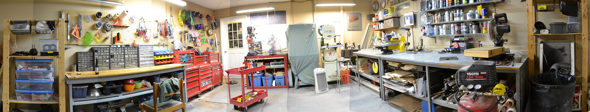
I recently spent the winter months moving into a new workspace. For the entirety of my career building props, I’ve made do in the less-used rooms of my house as well as my garage. This finally reached critical mass around October, and I no longer had the floor space needed for new tools and my expanding business. It took a lot of time and headache, but the new studio is up and running! I’ve moved out of around 540 square feet…
…to a little over 1400! (click on the pics for much higher res versions of these panoramas)
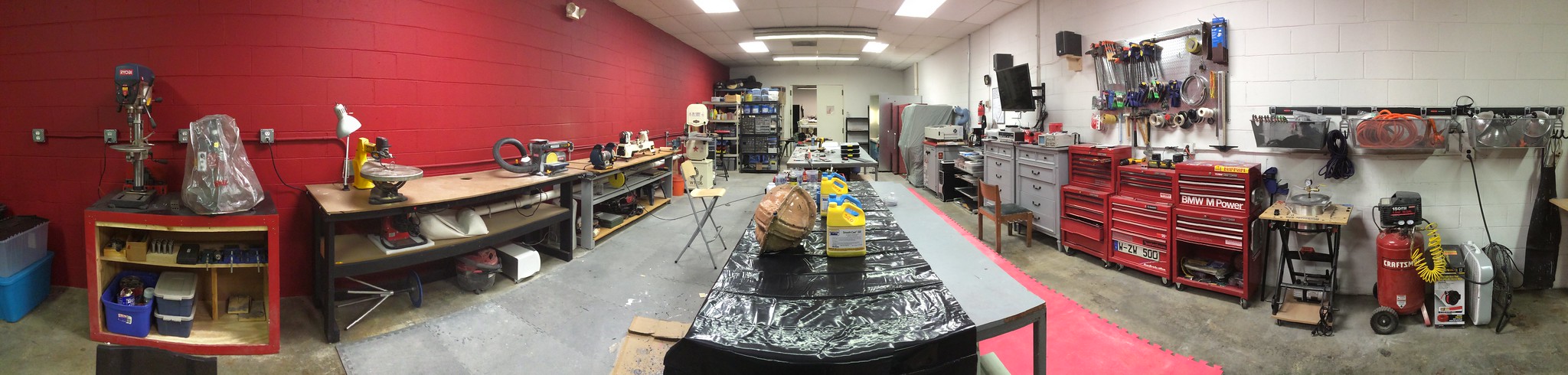
Since I was now in an industrial type space, the possibility of painting indoors with a spray booth was finally an option. Previously I was at the whim of the weather, but with climate control and proper ventilation I could now paint whenever I wanted to.
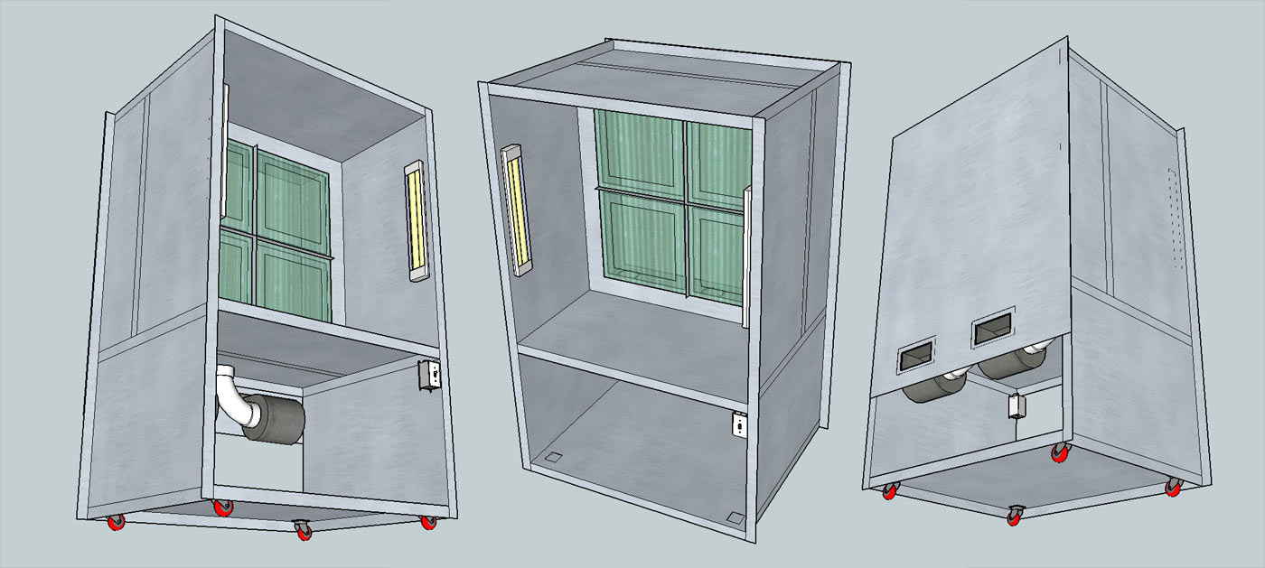
All I had to do was make a booth that complied with OSHA specifications and wouldn’t bankrupt me. I looked around at pre-fabbed pieces but I felt a bit like Goldilocks (without the breaking and entering) – the booths were either enormous and made for car painting, or tiny and built for 1:10 scale modelmakers. My ideal was something with a 4 foot square opening and about 2 feet of working depth. My initial designs were overly complicated and wouldn’t work with federal safety standards (you can’t make a spray booth out of flammable materials, for one)

Still, it was a start. I spent a lot of time fiddling in SketchUp and eventually had a design I liked that was streamlined for assembly as well. The entire piece would be built from 18ga galvanized steel. A local duct fabrication company – Dixie Duct – took care of all the metal shaping and cutting, and I was able to pick up finished sheets from them about a week after handing in my plans.

This thing is the largest tool I own now, and the SketchUp plans didn’t really prepare me for the scale of the project. Luckily, my dad came by to help with the assembly! There were 7 sheet metal components (I added an 8th in later) which would be bolted together along a 2″ lip on the perimeter of each part. We started out by framing up the sides and screwing the top panel in place. Clamps held the work table area square while we were drilling holes and adding screws.


At 24″ into the spray area, a baffle plate is mounted to hold the filter frame and filters in place. This looks kind of like a windowframe, and needed to be screwed together from the inside of the unit as it was laying down. We cut 16″ risers from some scrap 1×1 wood and used these to hold the frame at the proper height while it was secured.


I spent quite a bit of time in here. The spraybooth has somewhere around 300 screws that hold everything together and the steel ate through a couple drill bits during construction. Special shout out to my uncle James, who dropped off a couple dozen buckets of hardware at my dad’s shop back in 1998 that finally found a home in this project!


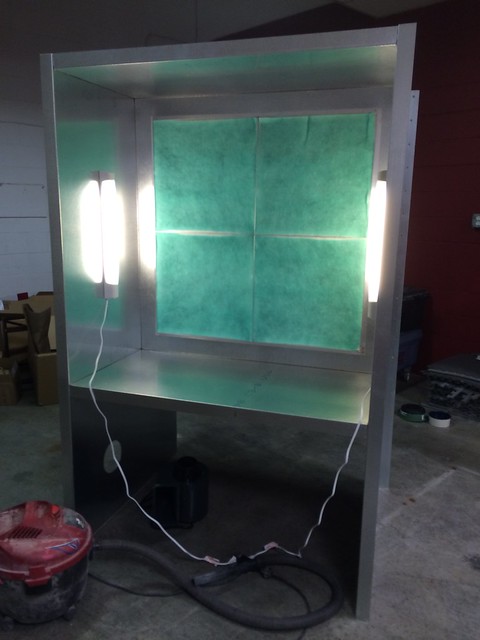
With the filter frame in place, the booth had enough structural rigidity to stand on its own. It was starting to look like something!

The frame that holds the filters in place is constructed from aluminum T-channel. There’s 24 feet of it here cut and riveted together to hold four 20″ x 20″ fiberglass filters. Behind these is a set of mesh filter frames that keep everything in place.

At this point I got antsy and chucked my lights into the booth to see how things were coming. Pretty good!

While the top was decently solid, the lack of a base plate meant moving this behemoth was a bit of a chore. Another order in with Dixie Duct and I had a base plate! I decided to put some casters underneath the skirt of this piece while I was at it, and now pushing the 300lb monster around the shop is a breeze.


Basic framework completed, it was time to add the suction and electrical bits to the project. Wiring is run through several conduit channels to the exhaust fans, lights and switch. A spare piece of conduit was added to the top of the booth to hang parts from while painting.


I found a cool paddle switch on Amazon to use, since I figured I’d be wearing clumsy gloves and such whenever the booth was in operation.

My original design used a somewhat complicated mounting plate for the exhaust fans. When putting things together I realized extending the rear cover plate down another 10″ or so would have been much easier, but this was already completed at that time. The new plans for this booth reflect these changes to make the build a bit simpler. The fans used are spark resistant squirrel cage blowers that move 500cfm a piece.

The exhaust vents for the fans were 8×3″ boxes that needed to feed into 4″ diameter tube. I couldn’t find this adapter for the life of me, so I cobbled up a buck from scrap tooling foam, MDF and PVC, then made a few copies in 1/8″ ABS plastic. I love having a vacuum former!


Here’s the exhaust tubing all set up. Right now this shares a chimney with the laser cutter, but it will have its own dedicated exhaust soon.


My first test run. Works great!

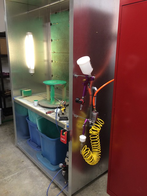
Finished booth. I’ve found out that primer will clog up a set of filters almost immediately, but spraying with my airbrush and HVLP guns is much much cleaner. Horray for indoor climate controlled painting!

If you’re interested at taking a crack at one of these yourself, you can buy my plans and 3D file of the booth in my store. This comes with an assembled and exploded 3D SketchUp file as well as a detailed PDF of the sheetmetal components needed for fabrication.
Thanks for reading!
All of the products listed in this write up are the products that I used and can recommend. Some of them are provided as Amazon affiliate links, which help support Volpin Props.
Sophitia’s Omega Sword, Soul Calibur IV
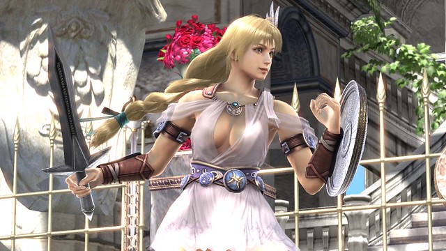
As a partner to the completed Elk Shield, I was asked to build a copy of Sophitia’s blade from Soul Calibur IV. The Omega Sword is actually quite similar to another weapon I’ve made a long time ago – Cassandra’s Digamma sword – but I wanted to try a few new techniques on this project.
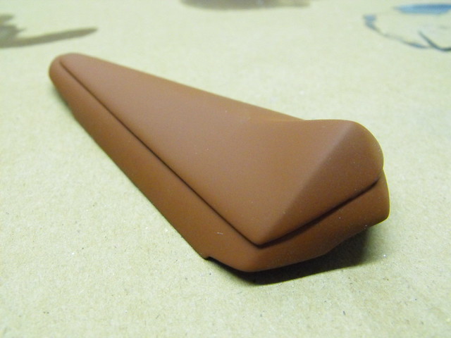
After creating a set of 2D blueprints, I set to work on the handle section first. The grip and pommel were both turned down from urethane resin blanks. The off coloration on the pommel comes from mixing two tinted resins into one cup simultaneously. This isn’t relevant to the project at hand, but it does look kind of cool.


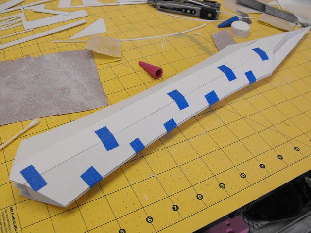
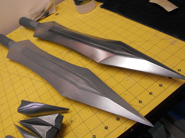
The blade was built in a pepakura-style combination of styrene sheets. This piece will end up being a master for a mold. While the technique I used made for an extremely lightweight piece, it would be very fragile. Good for less fatigue if you’re carrying it at a convention but you’d have to be super careful!
I started by trimming the center section of the blade out of some .060″ styrene sheet, then adding a center box for the raised shape that runs along the middle of the sword. To make sure this piece was secured at a 90º angle to the center blade spine, I used a piece of aluminum square tube as a jig when gluing it in place. Once one side was done, I repeated the process for the other half of the blade.


Small triangular parts were used as an interior structure for where the rest of the blade edges would be added. I also put in a few more structure-assisting shims along the center spine.

The side panels were angles I couldn’t determine exactly until the center of the blade was finished. For these, I laid paper over the opening and traced the pattern onto it, then transferred this shape to styrene. This shot shows one of the side panels being glued in place. This has a subtle compound curve down the side because of the concave blade shape.
This left me with a passable shape but it needed a bit of help to be crisp. Bondo was added in the seams and along the edges of the blade to make sure things were nice and pointy.

I repeated the process of sand, fill, repeat until the blade was ready for molding.


For the center raised letters, I lucked out and was able to re-use my mold from the Cassandra project. This piece started out as MDF sanded to shape, with styrene bar added around the perimeter for the raised details.

The lettering along the panel was cut at a local sign shop and added to the part before molding, so the finished resin piece would have a slight raised letter texture. This could also be done in reverse (letters cut out of a raised panel) if you were after a more engraved look.


For the cross guard and rain guard, I started with a few piece of acrylic that formed a perimeter shape. These were filled with apoxie sculpt and sanded down.


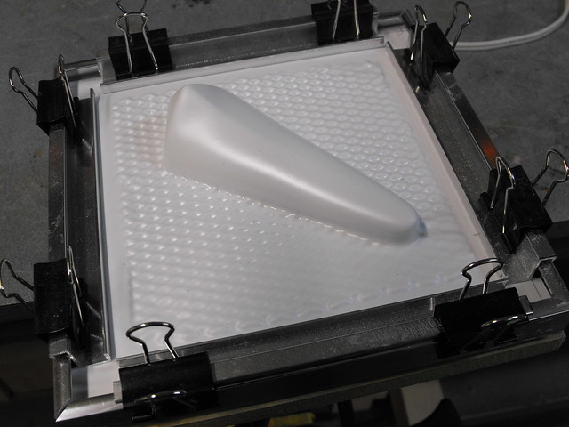
The rain guard was vacuumformed twice and the two styrene pulls layered on top of one another to create the final shape.
For the cross guard, I only made one piece – this would be molded and cast twice for one complete blade. Like the rain guard, a small piece of styrene was used for the raised detail.

Here’s the two parts being molded. I filled the rain guard with clay since it was a thin vacformed part and wasn’t thick enough for a pour mold without this backing.


The blade was also clayed up for a large pour mold. The silicone used here is Smooth-On’s Mold Max 40. All of the parts were cold cast, a process that involves adding metal powder to a resin casting in order to give the cast parts a surface that can be polished.


My process for cold casting is first to “dust” the mold with the metal powder. For these blade parts I’m using 100% aluminum powder. (This is essentially a can of tiny metal flakes, so make sure to wear a respirator any time you’re cold casting so you don’t breathe in a million little razorblades.) Dusting the mold involves pouring a lot of powder over the surface to cover the entire interior, then lightly tapping any excess out onto a piece of paper to be used later. You want a very thin film of powder without any thick pockets in the detail crevices. Too thin and it won’t polish well; too thick and the resin won’t fill the area. Ideally, you don’t want to be able to see the color of the mold material after powdering.
Some tutorials will say to add powder to the resin before pouring. I’ve had mixed results with this, as it can change the physical properties of the cured resin and make it more brittle. It can also trap air in annoying places. Most of the time, I only dust my molds and don’t add the powder to the actual plastic.


I also prefer to tint my resin gray to make sure any small missed spots aren’t obvious. Once you pull your parts out of the mold they’ll look dull and matte like this. When pouring, try to pour onto a part which does not need to be polished or will be hidden. The motion of the resin pouring into a mold will sometimes push away the dusted powder where you’re pouring and leave a small bare spot.

I start polishing first with some 0000 steel wool. This is very fine stuff and won’t last long before you’ll need to change pads. Don’t use too much pressure – you’re not sanding, just polishing. This will give you a “brushed” finish

For a polished look, I use aluminum wheel polish (my preferred brand is Mother’s) applied with a soft cloth. Excess in cracks and nooks needs to be cleaned out with q-tips or an old toothbrush. After a couple polishing passes, you’ll have a much shinier part! On the left in these photos is a piece with only 0000 steel wool, on the right is a polished blade.

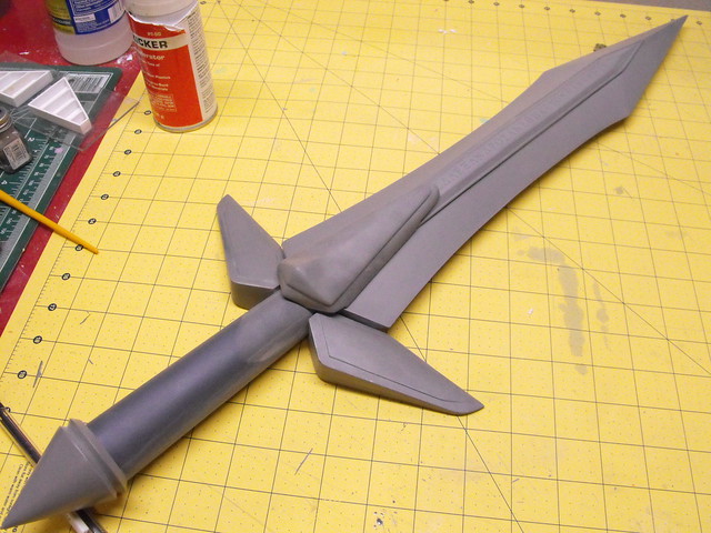
After polishing all the parts to a high shine, I drilled holes in the blade for mounting pins. Pinning parts will make them far more stable than just putting glue on a joint, and this is especially useful for cosplay props that get knocked around a lot. The clearances on these parts was a bit tight, which is why the pins are all labeled down to the thousandth of an inch. I used 2 part epoxy to secure all the parts in place.


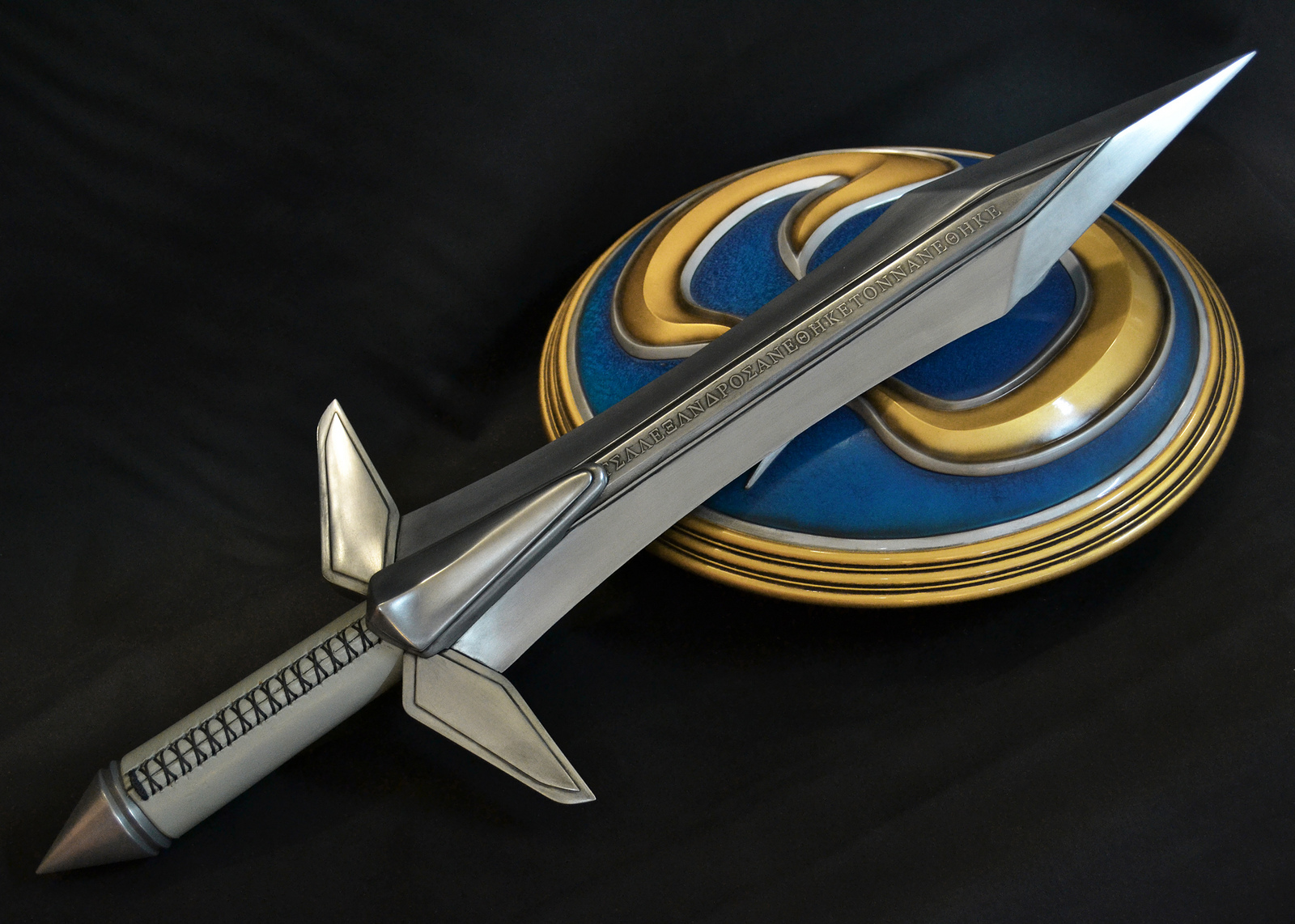
The handle wraps are gray leather and were created by my friend Cathy at God Save the Queen Fashions. After that, the swords were complete!

Here’s a few shots of the finished weapon – for higher res pics be sure to check out the gallery. For more process photos (I take too many to be included in every blog entry) take a look at my Flickr page.


Thanks for reading!
All of the products listed in this write up are the products that I used and can recommend. Some of them are provided as Amazon affiliate links, which help support Volpin Props.

Nightingale Bow, Skyrim
I decided to build a weapon as a companion piece to the Ancient Nord armor built for DragonCon 2013. There’s no shortage of cool things to make from Skyrim, but I had only had three days to devote to the project and I wanted to use as many existing materials as possible. I haven’t ever made a bow before, and after scrolling through the wiki a bit I decided that the Nightingale Bow had the perfect combination of aesthetic qualities and construction materials for what I wanted.

Blueprints were done in Adobe Illustrator.

I started off with some very light whitewood. These were chunks of a 1×12 I had sitting around from some shelves. I clamped two halves together and let them cure overnight.

To expedite tracing, I cut out one half of the bow from my printed blueprints and used primer to mark an outline. These shapes were trimmed on my bandsaw.


There was a lot of shaping after this, mostly done with a heavy rasp and a heavy tooth grinding drum. Thankfully the whitewood is little denser than urethane foam, so this work went quickly if a bit messily.

Here’s a contrast of a finished bow limb next to the raw cut piece off the bandsaw. Another benefit of this wood was the weight; a sanded piece weighed under half a pound.

Both limbs sanded and shaped. This was about 6 hours of work to get to this point.


The bow arms each were brushed with two coats of a polyurethane/stain mix. I had three cans of various dark colors that each had just a few ounces left at the bottom. By mixing them all together I had juuuust enough to coat the bow limbs.


The grip and arrow rests were a combination of MFD and PCV pipe. I trimmed the pipe ends off at an angle first, then drilled holes in the MDF at a matching angle on my drill press. Once assembled these parts were superglued together. There’s a recessed hole at the front to hide the bow limb mounting screws.


Each limb was secured to the handle with a 3″ long wood screw and a lot of wood glue.

I traced the pattern on the bow onto the limbs so I had an idea of where to sculpt the filigree. This was mostly done with a few patterns trimmed out of the printed blueprints and a few curves done by eye to blend those shapes together.

At the base of the limbs there’s a large amount of detail and raised metal parts. I was planning on sculpting all the shapes with Apoxie Sulpt but a chunk this big would have been heavy and expensive in material costs. I have a bunch of Smooth-on’s Free Form Air, which I used as a sort of sub-structure to fill in the larger voids.

Some time with the Apoxie later, here’s one limb detail section nearly complete. This is a rough sculpt, which I cleaned up later by sanding the cured surface.


After one half cured, I repeated the process to the second limb.

Here’s a head-on shot of the arrow rest. The cavity in the buttress was done with a set of hand files after the clay had cured.

There’s little Nightingale emblems that fit into the open wood areas on the front and rear near the grip. These were laser cut from some 2mm craft foam so they could be easily glued onto the compound curved areas of the bow after painting.


Speaking of painting, the masking on this thing took forever. I found the fastest method was to wrap the wood areas in tape and then trace along the edge of the filigree with an exact blade. This produced a fairly clean edge, and any slight misalignments were fixed with a bit of weathering later. The paint used here is Rustoleum hammered silver. I’ve got tons of this stuff sitting around.


Tape removed! Quite pleased with the results.


To pattern the grip, I wrapped the handle in masking tape and cut along one side. The tape was laid out on a piece of leather then cut to shape. I’m not much for soft materials, but I do like the braid/knot thing I came up with for the cover. It’s remarkably non-canon, which isn’t typical of me, but I like to be inventive every now and again when the mood strikes.


Since there wasn’t time to make a quiver, I only made a single arrow to pair with the weapon. The arrowhead is laser cut acrylic and the shaft is stained the same mixed color of the bow limbs. I wrapped the fletchings and arrowhead with jute, though this is really ornamental since they’re superglued in place.


The serving on the bowstring was a macrame knot done with more jute, and was strung in a way to hold the arrow nock in place even when not being held. The string itself is elastic and provides enough draw to pose with the bow, but not enough force to fire the arrow more than a few feet. This is supposed to be a convention-safe weapon, after all!

The final detail was a bit of grimy weathering and a few highlights on the raised edges of the filigree, then all done!


The completed project totaled around 35-40 hours and had almost zero new material costs.

Take a look at some higher resolution final images in the gallery, and if you’re interested in more build photos please check out my flickr page.


Thanks for reading!

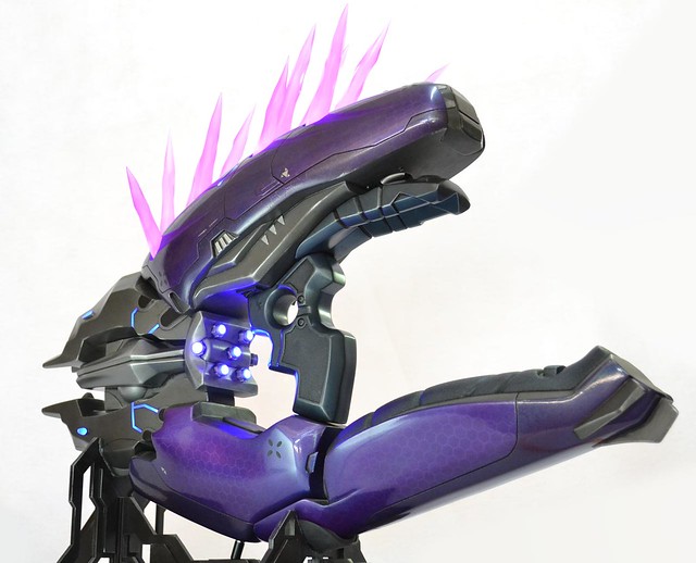
Needler, Halo 4/Reach
The HALO Needler has been on my personal list of stuff I really want to make since I first played HALO: Combat Evolved back in college. The design has undergone a lot of changes in the past 12 years and 6 HALO titles it has appeared in, but it’s always remained one of my favorites. The complexity of this thing rivals that of my Daft Punk helmet replicas, and I couldn’t be happier with the results.
If you’d like to see the whole process unfold before your very eyes in a bit under 4 minutes, then watch as 1400 build photos fly by in this recap video! That’s seven months of project time you’re watching.
This blog entry is going to be a bit out of the norm from my prior articles, because I’ve actually already written the whole project up over at Tested.com. The Needer was commissioned as a series of DIY/follow along build articles, broken down into 13 segments. Below are links to each one, and they cover their individual topics with great detail. Re-posting them here would make a blog entry ten miles longer than my most bluster-filled long winded article, so in order to help from destroying people’s RSS feeds, here’s a list of links to peruse:
Introductions – Well, if you’re reading this you probably know who I am and what I do already, but here’s a refresher for that sort of person that read every page in a book down to the publisher’s information.
References and Blueprinting – Exactly what it sounds like: how I make my blueprints in Adobe Illustrator and how to gather references from videogames. Also included is information on scaling props proportionally into the real world.
Selecting Materials – Plastics, resins, wood, and glue. See what I chose to make the Needler out of and why. Also covered are some of my personal favorite materials that get used on nearly every project.
Taking Shapes – Details my “slicing” and “ribbing” technique for creating complex geometric forms.
Bondo Strikes Back – Additional shaping of the above step, and how to create symmetrical details such as panel lines and indentations.
Details, Accents, Refinements, and Mockups – Taking basic shapes and adding in recessed areas, panel lines, and seamless intersections.
Introduction to Moldmaking – One and two-part block pour moldmaking

More Complex Moldmaking – Multi-part brush on molds with complex mold jackets.

The Casting Process – Creating hollow, clear and tinted resin castings from the molds created for the project. This covers mold prep, slush casting, and various kinds of urethane resins.
Illumination and Audio – Electronics for illuminated LEDs and a simple audio circuit with embedded amplifier.
Prepping for Paint – Cleaning up cast parts, priming, and filling casting imperfections.
Finally Time to Paint – Basecoating primed parts, airbrushing, complex masking and clearcoat.
Weathering the Needler – How to avoid the “toy look” by making shiny new stuff look aged and worn.
Putting it all together – Epoxy, wiring, soldering, nuts, bolts and screws. Time to make all these individual parts into one complete Needler!

Lessons Learned – Most of the time I really have no idea what I’m doing. Here are a few tips to avoid some of the mistakes I made, as well as a few personal favorite hacks from my bag of tricks.
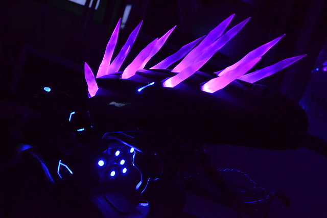
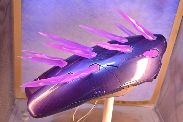
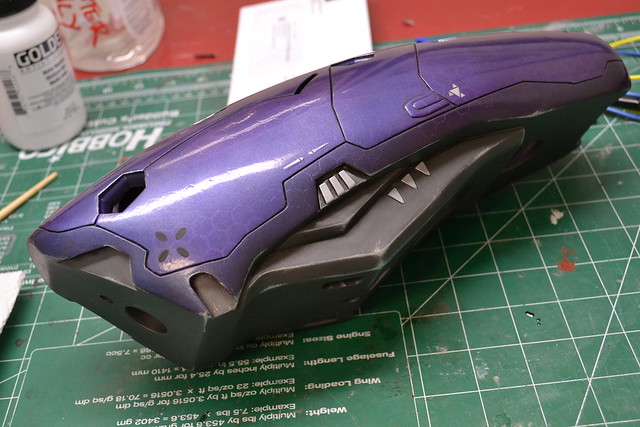
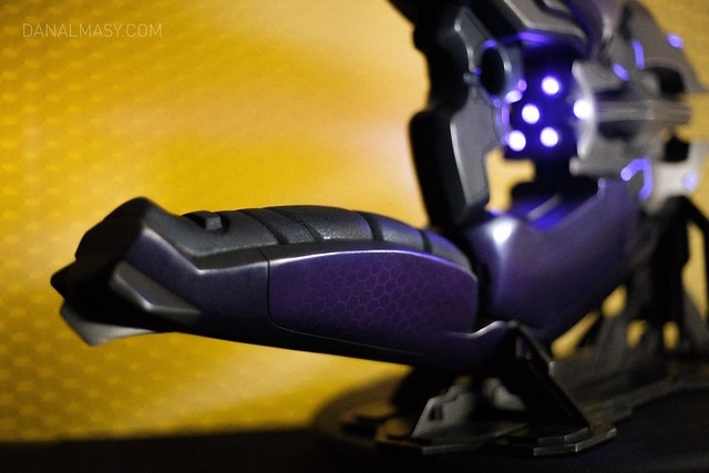
Here’s a few fancy shots of the finished product – watermarked pictures courtesy of Dan Almasy. You can find higher res shots of the finished Needler in my portfolio gallery.
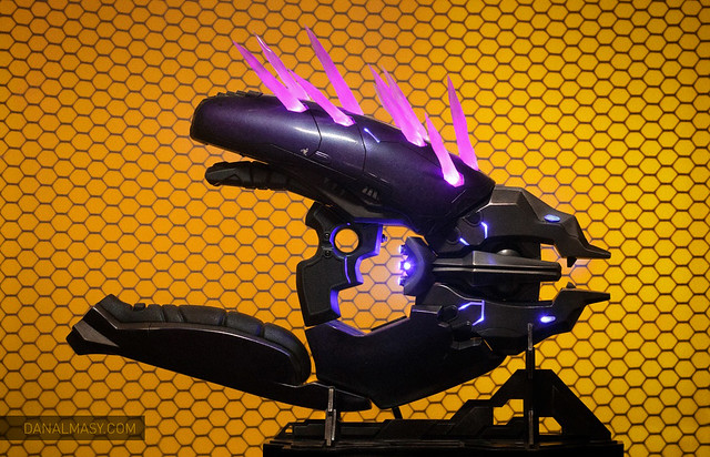


It’s a very fortunate artist who gets to select the works they are commissioned to build, and I can’t thank the guys at Tested.com enough for sponsoring this project. The Needler is something I’ve wanted to bring out into the real world for a very long time now, and I hope the articles above help you to bring your own creation to life as well. As always, thanks for reading!

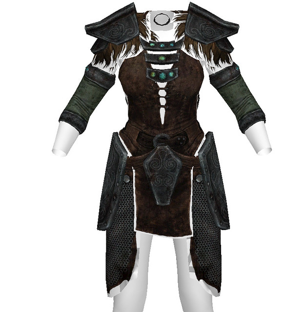
Ancient Nord Armor, Skyrim
It should come as absolutely no surprise that I’m a pretty big Skyrim fan. For DragonCon 2012 I made a set of Banded Iron armor for myself to go along with my helmet, axe and shield. I actually didn’t document that project on this blog, but instead detailed the process in a much more in-depth series over at instructables. That particular armor was done mostly with Wonderflex, a material that’s been around in the costume hobby for as long as I’ve been involved. It’s versatile and pretty easy to work with, but for my next set of armor I wanted to try out the new hot show in town.

Worbla is the name of the game this time, and anyone who is involved in cosplay and the convention scene has likely heard of it already. One of the most prolific artists to use this stuff is Kamui, a German costumer who makes amazing armor sets from (primarily) the Blizzard universe. I was curious about taking a crack with this stuff myself, and for the Ancient Nord Armor, I used a roll that I’d gotten from Yaya Han to try out.
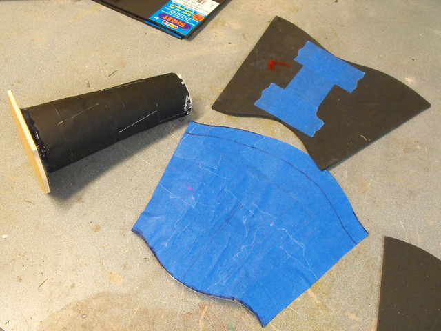
I spent a fair bit of time on scaling the armor and creating blueprints of each part. I was lucky enough to have a friend of mine (thanks David!) pull the 3D model out of the game and send it to me as an OBJ file I could manipulate in Photoshop. I gathered a bunch of reference and started making line art files for templates.
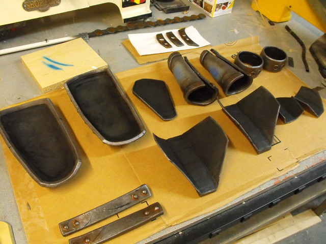
My approach initially was very similar to my Wonderflex build. Essentially Worbla is a low-melt plastic with embedded wood pulp fibers. The plastic gives it elasticity and adhesion to itself, and the fibers allow it to keep its shape. The downside is that, once heated, it sticks to pretty much everything. I’ve found that ducting tape is a good barrier to this, so I started off with simple cardboard forms wrapped in aluminum tape.
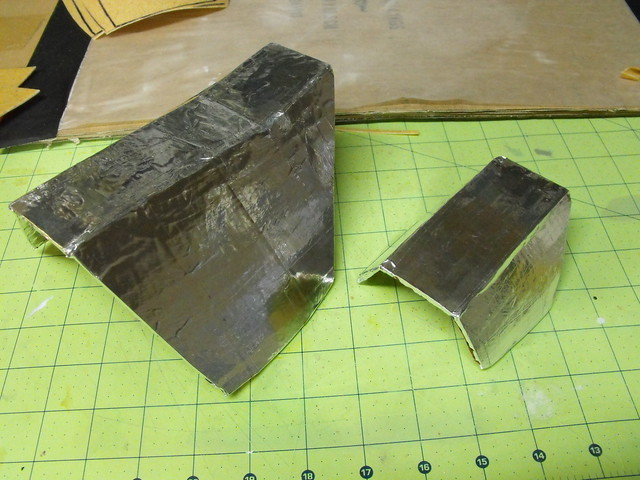
It is possible to shape Worbla without a form, but getting an exact curve will be trickier. For most things in this project I made a buck; the piece here is for the “crotch plate” and the buck was just a slab of MDF I had laying around.
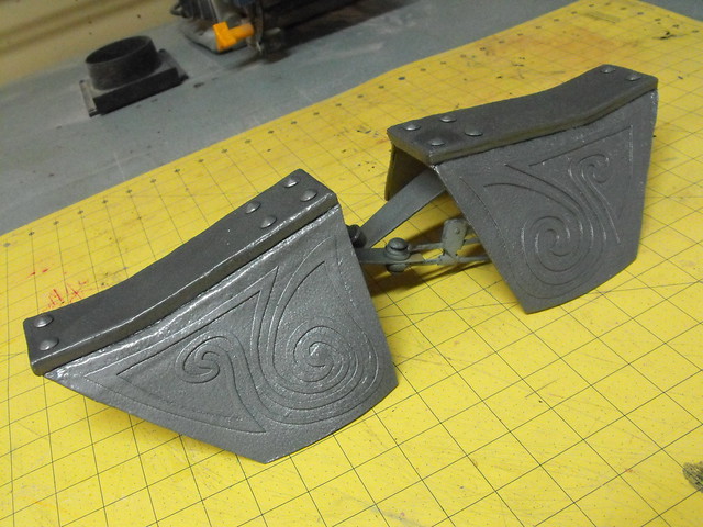
Here’s the base shape for the pauldrons. The large square block on top was made by wrapping 6mm craft foam with a sheet of worbla.
The hip plates were shaped mostly by hand. Since it takes some time for the material to cool and become rigid, I have found that working next to a bucket of ice water is very handy. Bend your part to the shape you want, then hold it in place while you submerge it in the bucket. The part cools quickly, sets into it’s desired form, then you’re free to heat a new section and tweak the shape as necessary.
The sides of the hip armor needed to be quite thick, so I repeated the craft foam layering along the perimeter edge.
Another cool thing I found out about Worbla is that you can cut it with a laser cutting machine! I will say the amount of smoke it puts out is pretty significant (similar to cutting MDF or other woods) so it’s a good idea to clean the mirrors in your machine afterwards. Still, being able to make super intricate shapes like this after tracing the patterns in Illustrator saved me hours of cutting time.
Here’s the hip plates again after adding “rivets” (just furniture tacks from Home Depot) and a bit of primer. Looks a lot more like armor now!
Same trick was repeated for the pauldrons. There were around 70 tacks on this costume all told.
Another laser cut filigree. I found out with this piece that you have to wait for the Worbla to cool after cutting before removing a piece this delicate. The first one warped and all I had was a twisted knot to show for it. Also, in this shot I have it taped to the piece of armor to keep it positioned while heating. This seemed like a good idea, but pins would have been better. The Worbla stuck very well to the tape once it was heated and those sections required a bit of repair later on.
First pass of primer. Something you’re not going to see here that was used a lot on my Wonderflex armor is filler and a lot of sanding. The Worbla has a pebbled rough texture that I decided to keep intact for the purposes of this armor. If you’re after smoother stuff you’ll need some sort of filler (gesso, filler primer, spot putty) but after priming these parts I thought the raw Worbla looked great. Wonderflex, by contrast, tends to have a definite woven pattern that doesn’t really match much of anything, which is why my Iron armor requires so much filler.
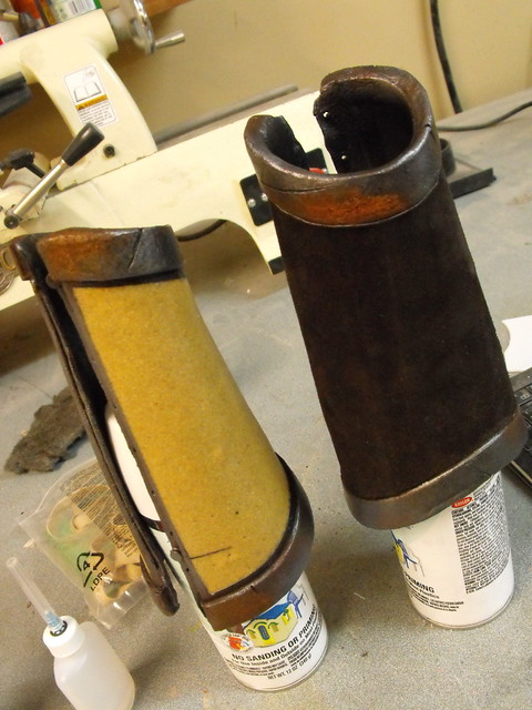
The wrist cuffs on this set were a bit trickier. There aren’t any seams or obvious way to get the parts on. I started with a tape and foam copy of my wife’s wrist (similar to a duct tape dummy, but only a forearm) and made a pattern in tape and craft foam.
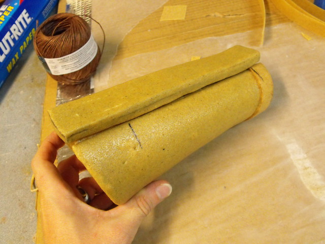
This was transferred to Worbla. I used a sheet of 2mm craft foam as a core to give it a bit more rigidity.
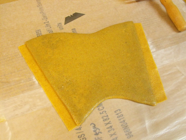
After wrapping around the arm copy and allowing to set, this is the basic shape. The large bar on top is made from 10mm craft foam, again wrapped in more Worbla.
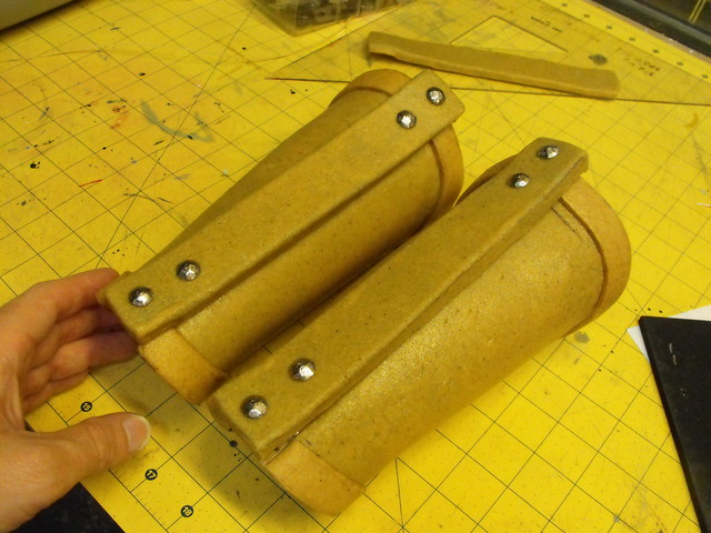
Since there isn’t an external clasp or seam, I hid the lacing for these under the large top bar plate. Six neodymium magnets on the bracer match up with 6 more embedded into the cover plate. Once the cuff is on the arm and laced up, the plate snaps into place to hide the lacing.
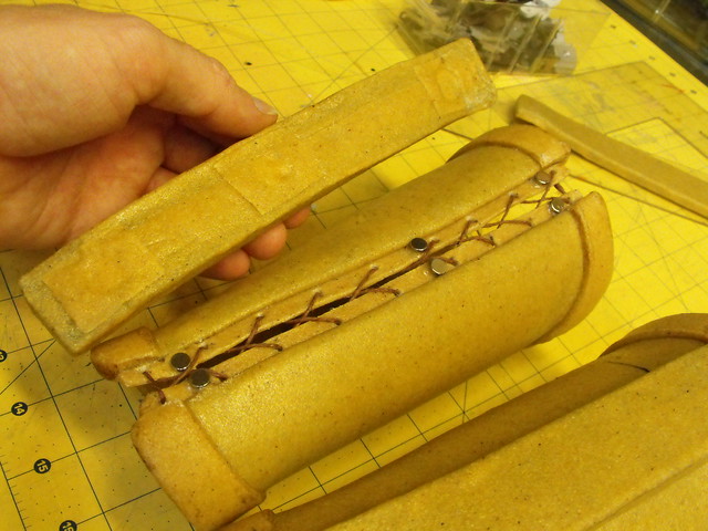
The last bit of detail here is something I found out with my Wonderflex armor and I think everyone should do with Worbla. By using a hot knife, you can blend edges and layers together to look like one solid part. On the left is the bracer edge, and you can clearly see the ~5 layers of material that make it up. On the right is Worbla thats been melted and blended tougher with a hot knife to make one continuous part.

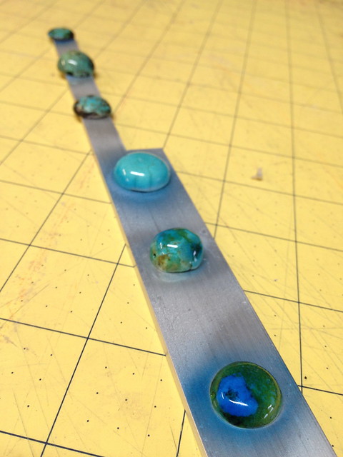
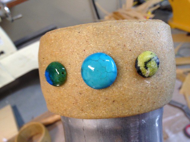
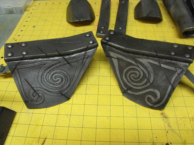
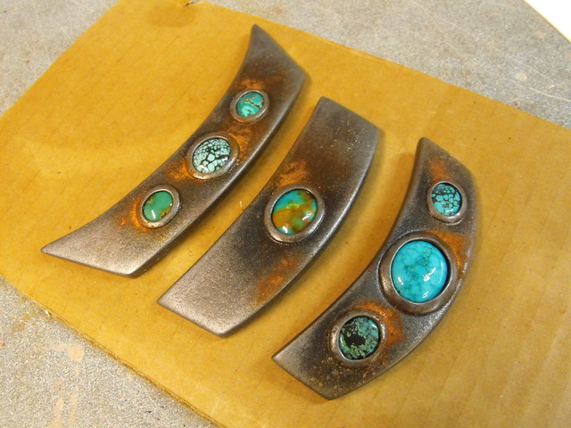
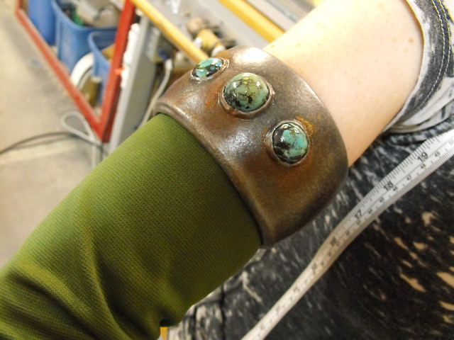
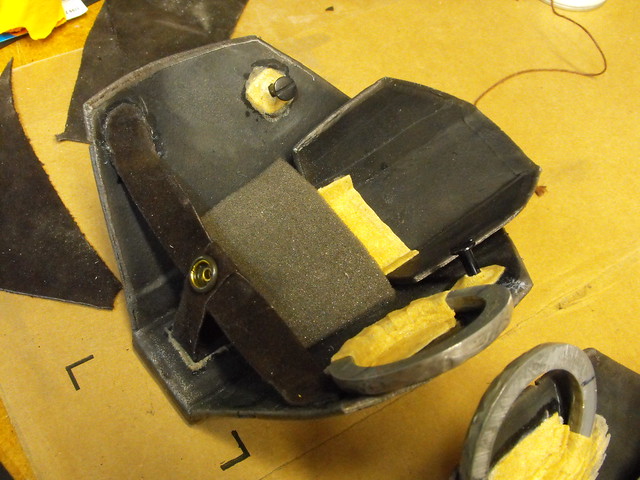
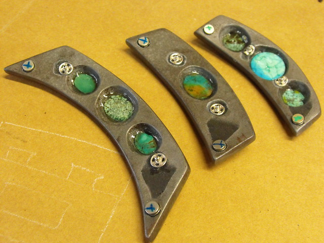
There are a lot of little blue and green stones on this set of armor (I think 13 in total) and my client (wife) was very very picky about which ones looked best and just how green or blue they should be. Trouble is, it’s hard to find just the right rock in just the right shape, so I got to learn a lot about lapidary – the process of shaping and polishing stones – in order to get everything just right. Some stones just didn’t have the perfect exact color though, and they got a bit of airbrush clearcoat in blue to tint them to the appropriate shade.
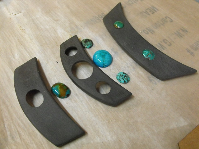
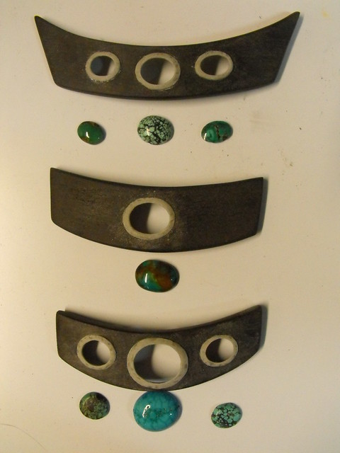
The necklace/chest part of the armor has 7 stones set into the plates. I used sintra for the armor itself, and cut out the insets for the stones from the back side so they would sit recessed when finished. The setting itself is made from Apoxie sculpt; I waxed the front faces of the stones, set them into the plates temporarily, then sculpted the settings around them. After the Apoxie cured I was able to pop the stones out (the wax prevented the Apoxie from curing to them) then clean up the setting with a small set of files.
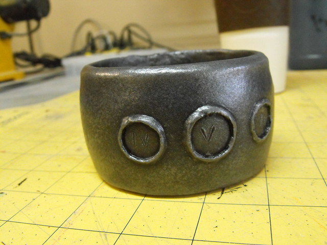
For the arm cuffs, I wasn’t able to set the stones in from the backside, so I used a small bead of Worbla wrapped around the perimeter and secured with a hot knife to make the settings. They’re rougher, but I think the end effect is still nice.
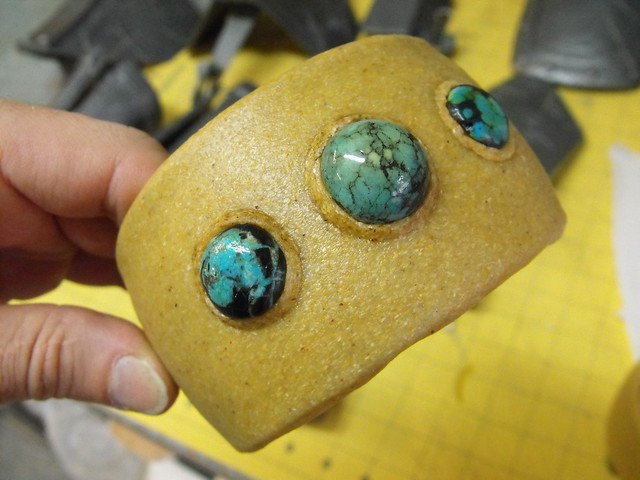
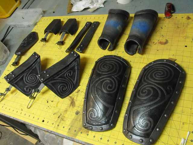
After removing them I labeled all the stones with a numeral so I’d know which ones went where later on.
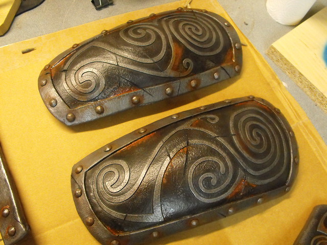
With all the armor constructed it was time for paint and weathering. I started off by coating all the parts with primer, then Rustoleum Hammered Silver paint. This stuff is super durable and great for costuming. Each armor piece received 2 thick layers and was left to cure for 72 hours.

After the paint dried, I took a dremel tool and cutoff wheel to the plates and carved in a bunch of slash marks. Half of these are game-accurate but since the texture map just mirrors damage from the left to right sides, the other half is my own haphazard placement. Deeper gouges were accentuated with a hot knife after using the dremel.

Weathering is a layering process and there were several steps to get to the finished product. First, the entire part was covered in a mixed acrylic brown, then excess paint was wiped off with a damp rag.
You can see the contrast in this one step alone between the two parts here:
I tried a process intermittently in the weathering that a friend had suggested to me a while ago, and used a small sponge roller with metallic silver paint in between passes of weathering. This gives the armor a sort of iridescent sheen and helps it look much more metallic.

The next step involved airbrushing a more washed out brown, nearly gray, into the background parts of the armor. Any overspray onto the edge or filigree design was wiped away with a damp q-tip.
More contrast between this step and the previous one:
After all the airbrush work is finished, all parts got another light pass with the silver metallic sponge roller, then were left to dry for 24 hours. They were coated with acrylic matte clearcoat, then left another 24 hours for full cure. When it comes to painting, it’s really best not to rush.
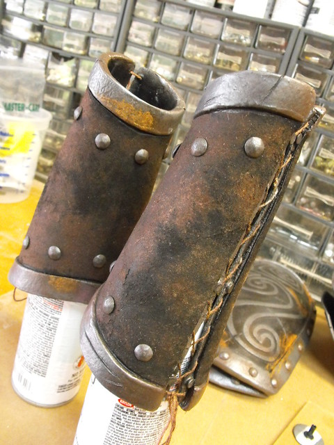
With all the undercoat and clear sealer cured, it’s time for rust! This is my favorite part of old armor, and I’ve detailed the process many times but here we go again. Start off with Ferrous Iron Powder – not red iron powder – this stuff has to be gray. If its any other color (red, yellow, etc) it’s already oxidized and won’t rust again.
The powder is applied to the armor by wetting a section of the part, then lightly dusting the iron powder over the damp area. This will get it to stick in place. After you’ve got the armor dusted to your liking, you’ll need to mix up something I call “hamster pee” – thats a mix of 50/50 vinegar and hydrogen peroxide, with a bit of iodized salt. Once you mix it up, you’ll know why it has earned that awful name in my shop. Spray this awful concoction over the rust powder and watch as it bubbles and transforms into rusty armor! Leave it to do it’s chemical thing overnight, and you’ll be greeted with pretty orange and red rust the next morning.

Oh, and lay down a sheet of cardboard or something, because you don’t want rust runoff all over your workbench, floor, carpet or otherwise. It’ll never come off.
A last bit of soft work needed to be done to complete the bracers. While painting, the Worbla in the middle area was masked off to stay clean. This allowed me to epoxy a leather insert in place later on without needing to scrape away any paint.
The leather needed to look old and grimy – it is Ancient Nord armor after all – so I went after it with several passes of bleach and acrylic paint in various spray bottles. It might be a little scary to spritz bleach all over an expensive leather hide, but weathering really does make the difference when it comes to believable props and accessories. That said, always try on a test piece first!
I also like to paint all of the armor inside panels flat black to hide any wonky seams or weird patches that might show in photography later on. This is a luxury if you’re not rushed before the convention, but I think it helps the final product a lot.
The very last part – and unfortunately the most rushed aspect of this and lacking in photography – was strapping and rigging. I cover that in a bit more detail in my Wonderflex tutorial, but really it’s a matter of placing snaps, chicago screws, D rings and blocks of foam everywhere until your armor hangs right. Sometimes this can result in some odd looking arrangements, like the inside of the pauldron here.
For other parts, think outside the standard. When the snaps on the chest plates resulted in a weird hinge-forward look, my wife suggested we just use magnets to hold them in place. The inside ones aren’t even attached to the costume itself; they just hold the plates on through the fabric, allowing for easy repositioning of the part.
Now, I can’t sew to save my life, so really the bulk of this costume credit needs to go to Emily for all her hard work on the leather, fur and chain mail. I did make the bow though (write up coming soon!) and had my first trial with airbrush makeup as well. Fun times!
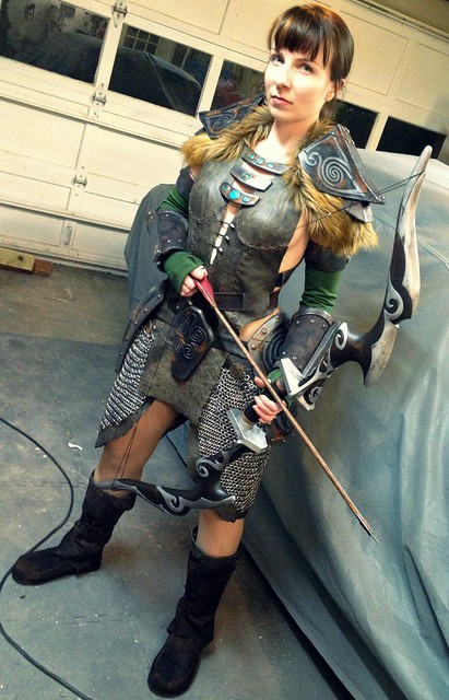
Photo (below) courtesy of and © Joseph Lin
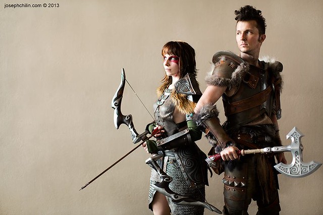
Photo (below) courtesy of and © chriswithcamera@gmail.com
Thanks for reading! There are more progress shots available over on my Flickr page so be sure to check those out if you’re interested and want to see my latest up-to-date progress!

Holophonor, Futurama
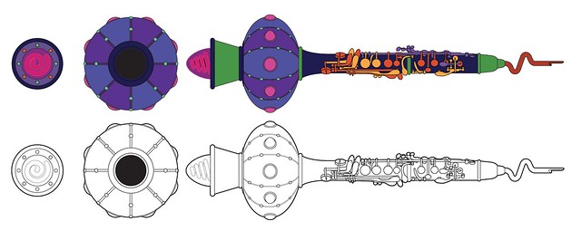
At the beginning of the year I put a post up on my facebook page listing off some various replicas I wanted to make in the hopes that some people might ask me to build them. I feel like I do my best work when I’m really invested in a project, and it was my hope that there were like-minded fans out there that would think some of the crazy stuff I felt like building was something they’d feel like having built. One of the stranger ones was the Holophonor, an over the top holograph-projecting clarinet/oboe hybrid bristling with lights.

I had a client express interest in having a full scale real world model built, so I started gathering about a billion screencaps from the series. Since Futurama is hand drawn, the Holophonor varies wildly from shot to shot. Sometimes whole sets of keys are missing, sometimes it looks about a foot shorter then normal, and the lower bell seems to be anywhere from 6″ around to over 18″ depending on which frame you’re looking at. I fired up Netflix and grabbed a ton of reference. The keys in some of the more detailed shots reminded me of a clarinet, and the more I checked, the more that I was certain the Holophonor was inspired by one – the grouping of the 4 long keys at the bottom, the same number of front facing valves, even the very long upper hinged keys. I drew up some blueprints.
Since this piece is mostly a clarinet, I decided to mod an existing instrument instead of building one entirely from scratch. After scouring craigslist for a used piece, I found a, uh, “winner” – a $70 “Vito” brand clarinet at a thrift shop downtown. This thing was disgusting. I don’t know who owned it or for how long, but it was filled with… well, it was gross. We’ll leave it at that.

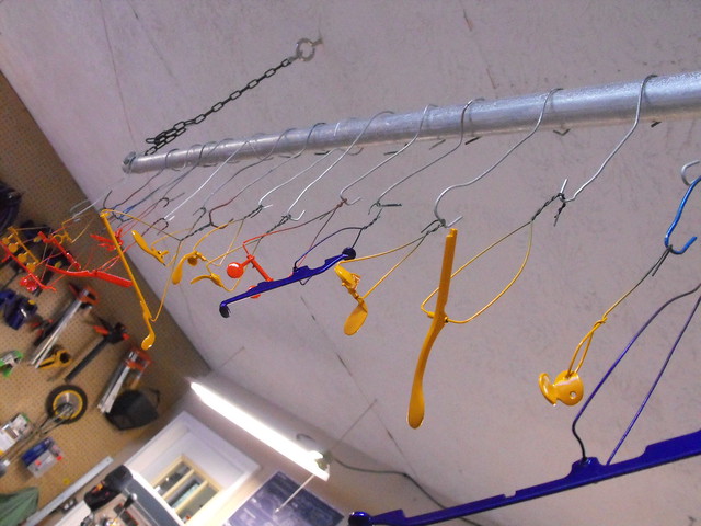
Referencing the blueprints, I marked keys and triggers with different color paint pen before dis-assembly. This way I know which ones to paint what color later on down the road. I also took a ton of photos like this, as well as some time lapse shots of the tear down, so I’d know how things should be assembled when the time came.


Fun fact if you’re planning on doing this – cheap plastic clarinets are injection molded ABS plastic. Those little standoffs in the pic above aren’t screwed in – they’re pressed in place while the peg is heated, and the cooling plastic keeps them locked in. To remove them, I heated each peg carefully with a blowtorch to soften the surrounding plastic, then pulled them out before it cooled.

The body isn’t a perfect match – the lowermost valve is missing on the Holophonor, and has been replaced with a widened bell that flares out before meeting up with the illuminated ball on the end of the instrument. I had to lop about 2″ off the bottom of the clarinet body, which I did with my lathe.
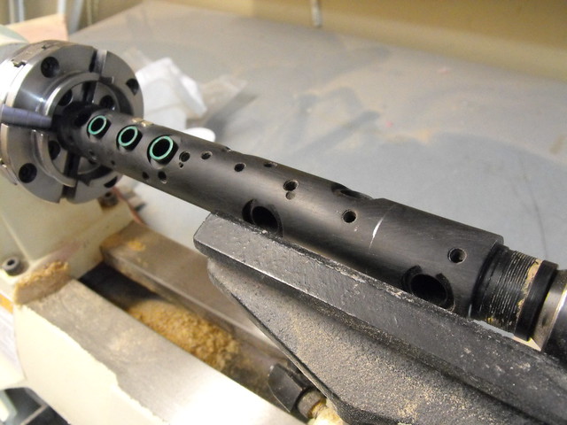
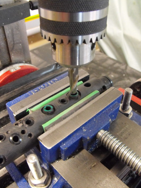
The Holophonor also doesn’t have any open keys, so these need to be plugged. The body of the clarinet has raised portions here that also needed to be milled flush if the keys were getting capped off. The associated open keys were filled in with epoxy clay and sanded smooth.
Now it was for a lot of lathe work. I made some turning blanks out of smooth cast 300 and black dye. I think the dye actually makes lathing this a bit easier since you can more readily see what you’re doing than with white plastic. These chunks became the following parts:
The “mouthpiece” where the eventual reed will sit.

Flared bell to replace the 2″ of the clarinet body I lopped off.
The lower horn.

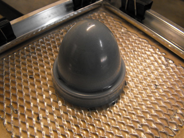
Lower horn with bulb blank inserted. The bulb will eventually be vacformed from clear PETG and dyed red. This is just the vacform buck.
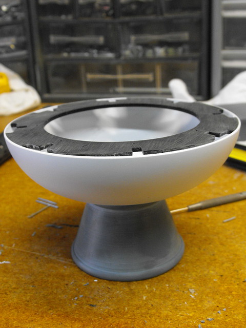
The illuminated lower ball is going to be made from two styrene halves. I made the vacform buck from some 20# urethane tooling foam.

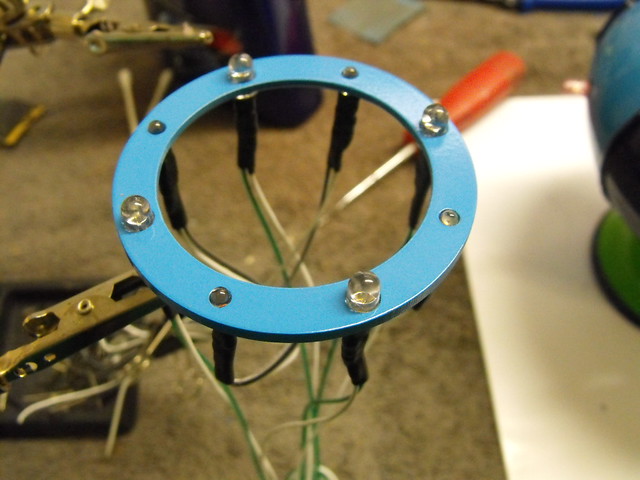
I pulled the two halves in .060″ styrene and made a support ring for the interior. These shapes serve a few purposes. First, they make sure the dome keeps a consistent shape. Second, they have small holes so the two domes are registered to one another for assembly. Third, they provide mounting points for the curcuit board and perimeter LEDs, and lastly they give me a point to sand the domes flush to. I ended up not needing the circuit board flat mounting point, and really it just got in the way while I was installing the LEDs…
The, erm, lower horn is mounted to the lower section of the bell with 4 screws. Once the two halves are assembled, this guy isn’t going to be able to be removed again.

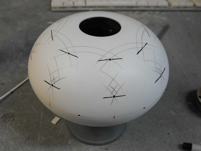
Two halves glued up, and seam filled. The small holes are markers for the perimeter pink LEDs.

From these little holes I was able to extrapolate the distances to the 8 rows of 4 LEDs that make up the 8 painted sections on the bell. First I marked everything up and drilled small pilot holes where the 4-row LEDs would sit.
Added some .1″ styrene to the bell and drilled out the LED holes – started with a small drill bit then gradually moved up to an engraving bit on my dremel to open to holes up.

Mockup of parts in place. This is also after I blended the upper horn into the clarinet body.

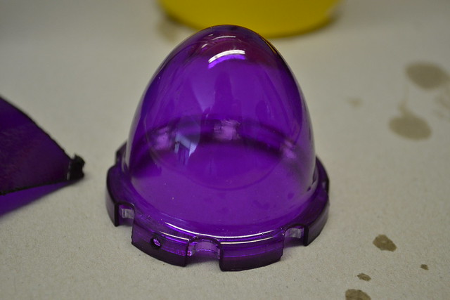
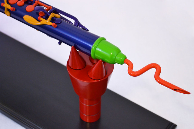
After this I spent some time on the little bulb thing at the end of the horn. The dome itself was vacformed from 1/16″ clear PETG
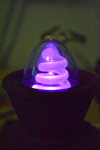
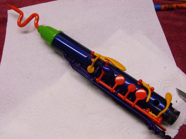
The little curly element inside is 1/4″ acrylic rod. I heated it and bent it around a cone-shaped piece I had left over from a previous project to get the tapered spiral.

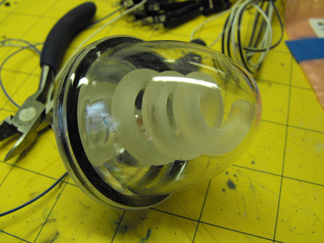
(I also used the same acrylic to make the wonky reed/mouthpiece thing)

I dyed the lens purple with Jaquard “iDye Poly” which was suggested to me by my friend Eric. It has to get hotter to dye plastic, but it does a much better job than RIT and the color is much darker, achieved after just one pass in the dye bath.
The squiggle thing is illuminated with 2 pink 5mm LEDs.
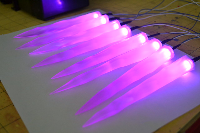
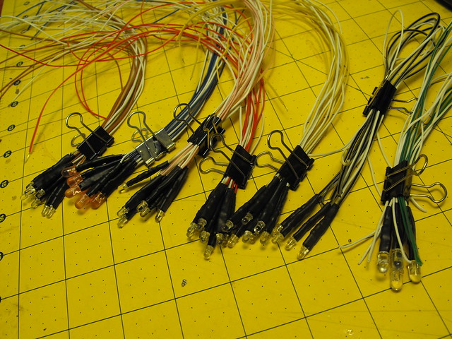
Speaking of LEDs, I spent a looooooong time soldering pigtails for the 54 LEDs that will be housed in the lower bell. There are 40 aqua bulbs, 10 pink, and 4 orange.
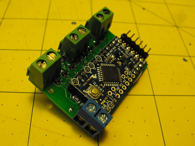
I also designed a breakout board for the Arduino that will end up controlling the illumination sequence. For this I needed 4 fading channels and 4 blinking channels. I’m not exactly a coding genius, so this took me a little while.
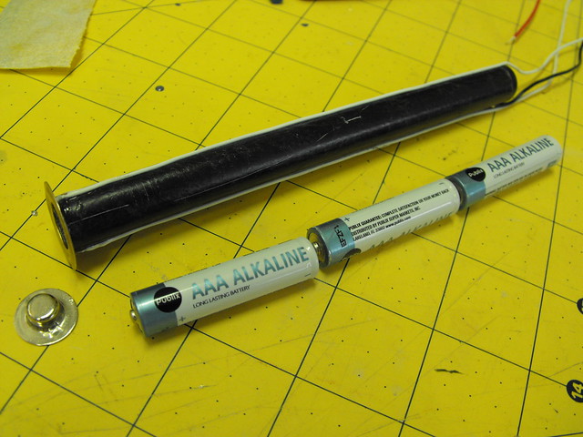
The holophonor needed to be able to illuminate from battery or a wall power adapter. A 3 position (on-off-on) switch selects power from either 3 AAA batteries housed in the lower section of the main body, or from a jack situated just above the power switch that will eventually go to a wall AC adapter.

I couldn’t find a battery holder that would fit inside the clarinet body, so I needed to make one from scratch. The tube here is a piece of fiberglass pipe with a small spring secured to its base. This spring is soldered to a wire which makes up the ground connection for the 3 AAA batteries. Up top, a steel ring is soldered to two white wires which make up the positive side of the circuit. When batteries are placed in the holder they don’t make a connection until the clarinet is assembled. A metal plate secured to the upper section of the clarinet body completes the circuit on the positive side when the two halves are put together.

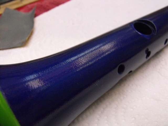
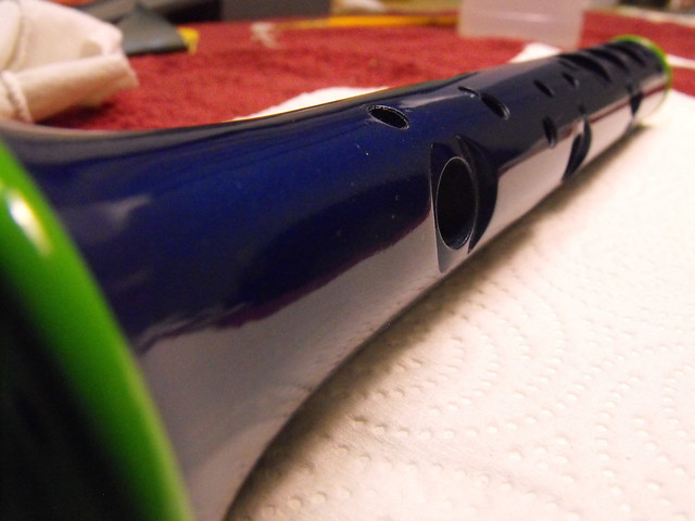
With the fabrication complete, it was time for paint. The paint I’m using here is Testor’s spray lacquer in a multitude of shades.


I spent a lot of time wet sanding orange peel out of the clear coat for a smoother look. 2,000 grit paper, then fine cut rubbing compound, then a few coats of wax makes a huge difference.
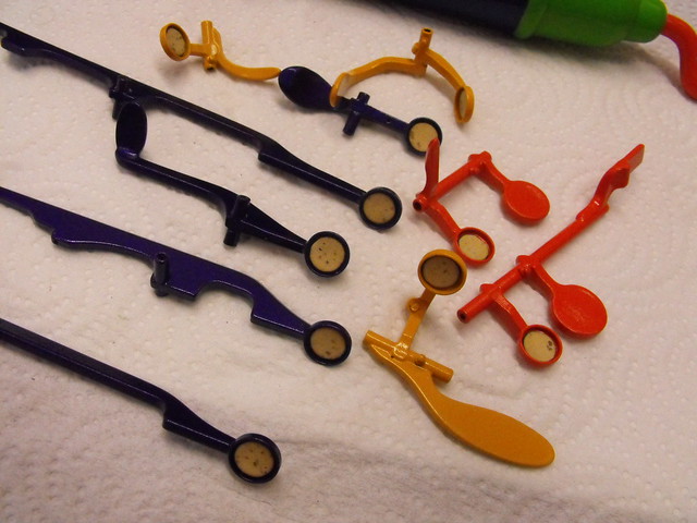
Each of the metal keys was first prepped with a wire wheel before zinc etching primer to make sure the paint would be as resilient as possible.
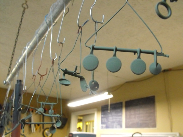

I added cork pads to keep them from scratching the finish on the main body when they’re pressed down.
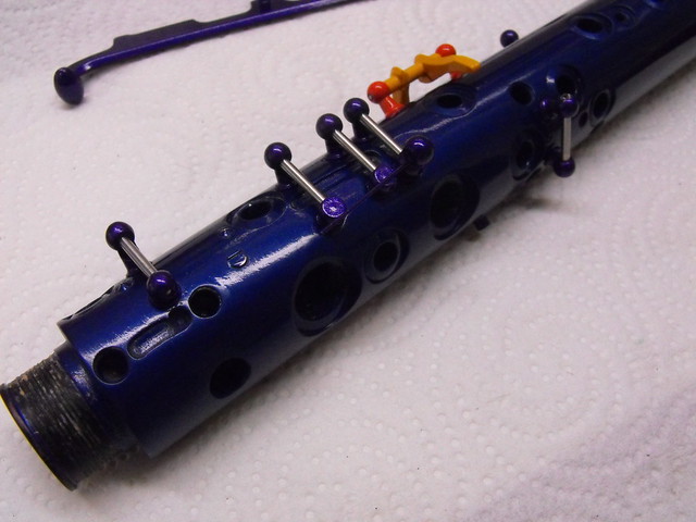
Assembly was very tedious and nerve wracking. All the mounting pins were first epoxied into place with their pivot pins in place to make sure they were all in register to one another. Once that cured, the keys were screwed into place.
It took quite a long time to get all the LEDs glued in place. I used 5 minute epoxy to secure them but because of their somewhat loose mounting positions I could only do 4 at a time before leaving the assembly to cure. If I tried to do more than that I’d knock the other ones loose from bumping up against the wiring.

Here’s a shot of the wires for the first two rows of green and half of the pink LEDs. That’s about 1/3 of the wires that eventually fill up the bell. In retrospect I might have been able to daisy chain them together to make the wires shorter, but I’m not sure if that would have made mounting and assembly more difficult.

This is the light ring that goes around the curly bell at the bottom. 4 orange 5mm bulbs and 4 green 3mm.
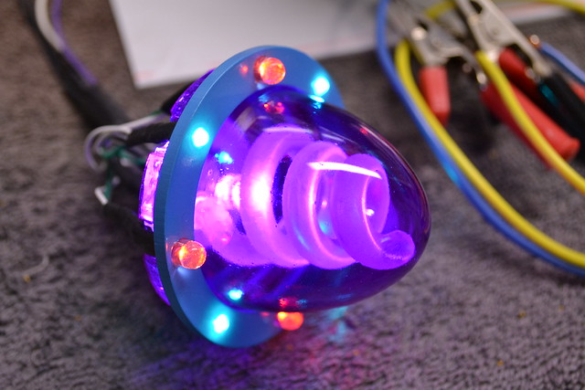
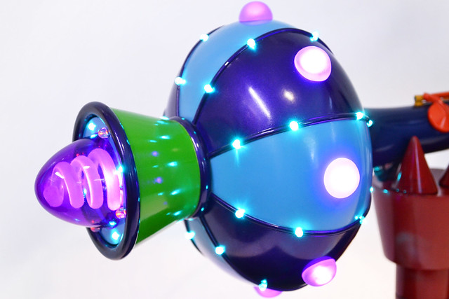
And all illuminated! This part is BRIGHT. The Holophonor might not be able to project holographic images, but it will make cool patterns on the wall from 15 feet away.
The large pink lenses that fit over the perimeter lights were sculpted from apoxie sculpt then pressure cast in translucent pink resin.

In order to get the lens bases to fit flush against the side of the holophonor bell, I made a sanding jig. The profile on this piece is the exact shape of the perimeter of the holophonor. By sanding the lenses in one direction along its perimeter, each piece was shaped to fit flush against the lower bell over the pink LEDs
These lenses were epoxied into place over the pink LEDs and left to cure overnight.
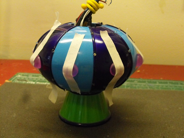
Here’s the Holophonor with all the wires crammed inside and running the blinking code off an Arduino Mini.

At this point the instrument was pretty much complete, but it needed a fancy display stand. I think anyone familiar with Futurama would see where this was headed.
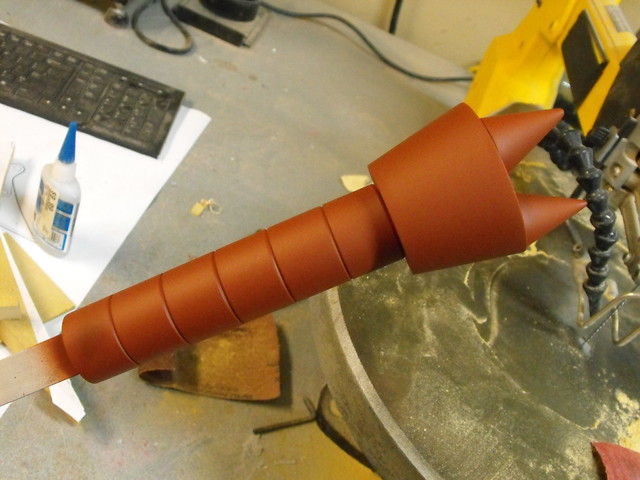
Obviously you need a set of Robot Devil hands if you’re ever planning on playing the thing! I made two copies and ran the power supply wire up through the one situated near the lower bell. A poplar base was painted semi gloss black for that classy look.


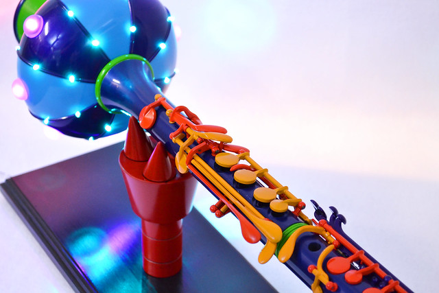
Here’s the finished product! I can say this is definitely one of the stranger things I’ve ever built, and I’m very glad to have had the opportunity to build it. I just never want to take apart and clean a thrift-store-purchased clarinet again for the rest of my life.
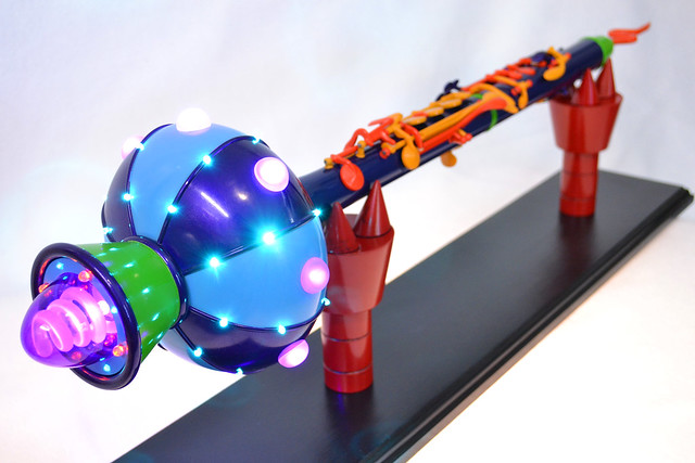
Check out the gallery for more finished photos, and my Flickr for more in-progress shots.
Thanks for reading!

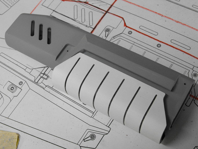
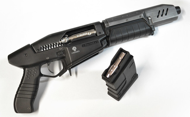
Militech Crusher, Cyberpunk 2077
Back in January I got an email from one of the PR reps at CD Projekt RED about a potential replica to showcase a new game from a familiar franchise. For those more into the tabletop RPG scene, the name Cyberpunk is probably an old favorite, and the guys at CD Projekt RED will be bringing this universe to the video game world with their upcoming title Cyberpunk 2077.

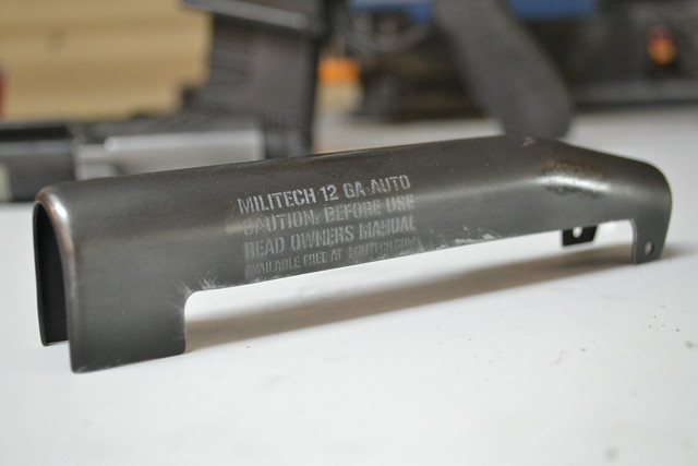
The replica they were after is a new take on a staple of the series, the Militech Crusher. This new version fired 12ga slugs and is a sort of SMG layout with a short body and forward grip. It’s a deceptively complex design that was challenging and very fun to build. I got a lot of references from the studio, and started out by drafting some 2D blueprints.
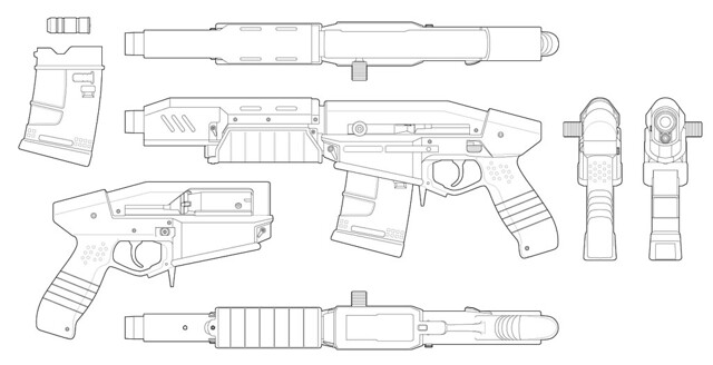
There are a lot of individual pieces to this gun, so I’ll talk about their construction separately.
Many of the parts were trimmed on my laser cutter to create the inner framework for things like the magazine and barrel shroud.
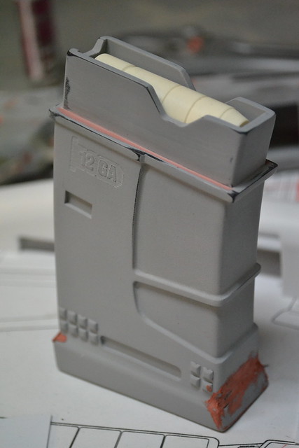
Laser cut acrylic was used for 90% of the gun magazine. The curved forward and back sections were made by bending styrene into place along the curve of the acrylic and gluing it into place.
A ribbed detail on the bottom of the magazine was made by using textured styrene. You can get this stuff at many hobby stores and it’s typically used to make model housing for railroad scenes.
Here’s the magazine after a few coats of primer and a little spot putty to fill in the gaps. The small squares at the base of the part are plastic stick-on shapes used for scrapbooking. These types of things come in handy a lot more often than you’d think!
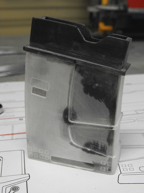
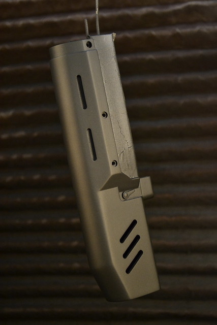
Onto the barrel shroud – this needed to have a curved upper section, so 1″ PVC pipe was cut and sanded to shape and glued in place. I repeated a similar technique in making the vacuum-form buck that would eventually be used to make the rear bolt shroud.
The rear angled face of this part was made with apoxie sculpt blended into the small step on the side of the shroud. There was a lot of sanding done to make this look like a smooth transition but (unfortunately) with the deadline and turnaround being pretty quick, sometimes my photography of the process suffered a bit.
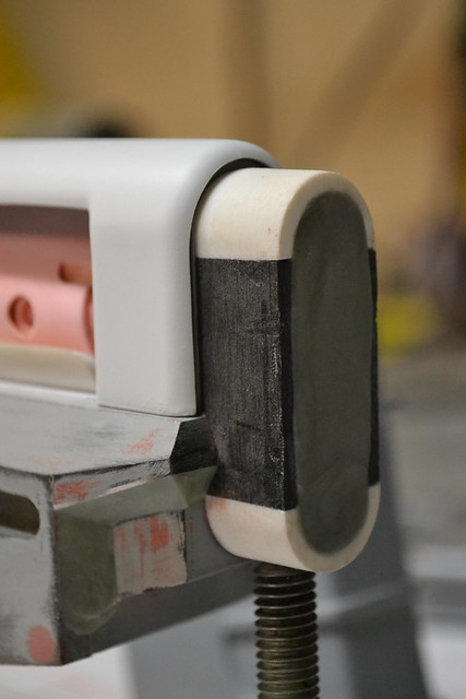
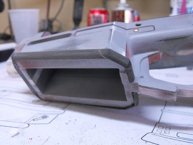
Mounting the barrel shroud to the main body of the gun was something I thought about for a while – this needed to be a very stable intersection as it would hold up the entire front part of the prop. The back section of the barrel shroud had an oval-shaped cavity built into it which would eventually fit onto a matching plug created on the front edge of the gun body.
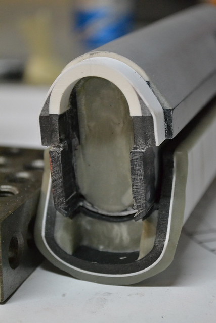
I discovered new and terrifying angles with my mill when I cut out the oval slots on this part. Nerve-wracking, but it turned out very clean!
Thicker pieces that I couldn’t trim on my laser were hand cut on my scroll saw. These three layers make up the bulk of the main body of the gun and are 6mm sintra. I used a white center spine to more easily determine the symmetry of the part.
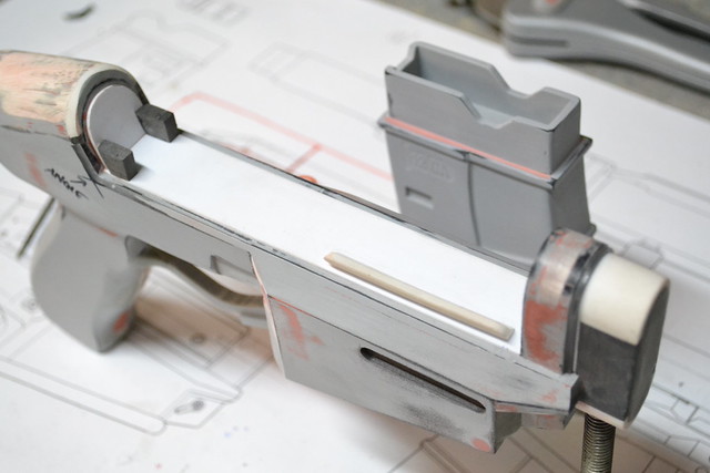
The main body needed to be able to house a removable magazine, so a square cavity was left in the lower portion during assembly. The side walls here are made up of .060″ acrylic.
An in-progress shot of a lot of components in their earlier stages. You can see here how the areas around the magazine well were built up in thickness by using 8mm sintra and styrene for the angled bevels.
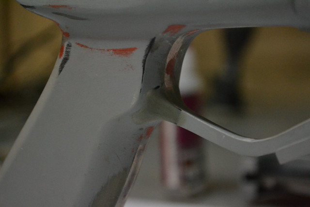
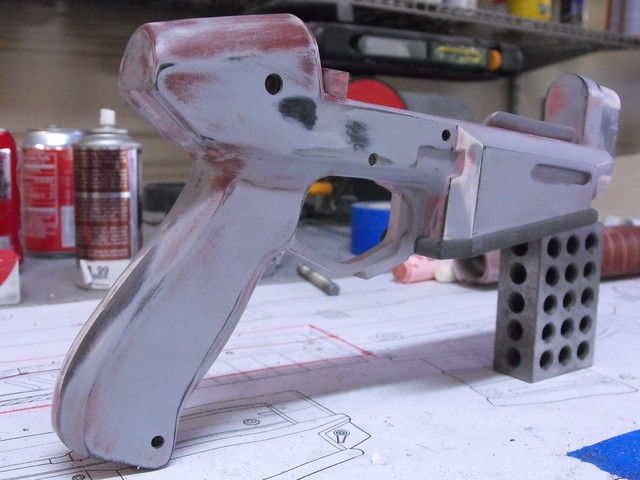
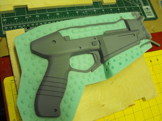
Contoured areas around the grip and trigger were added with apoxie sculpt and sanded down to a smooth curve.
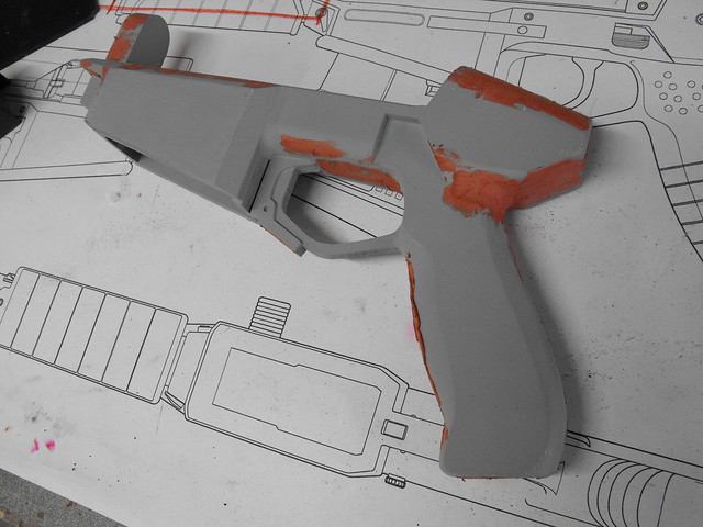
The upper portion of the gun was smoothed out with a piece of .020″ styrene. This was much easier than trying to sand all the individual layers perfectly flat. The two black tabs at the back are mounting points for the bolt shroud.
Recessed parts of the receiver, such as the logo indentation and magazine catch, were slotted on my mill. The mag catch was made with thin styrene.
A rounded accent encompasses the perimeter of the mag well. I couldn’t get half round stock in that thickness (and the part itself has a slight upward angle to it making it not *exactly* half rounded material) so I cut sintra strips out and sanded them to shape before gluing them in place.
A bunch of holes were milled into the gun body for recessed screws.
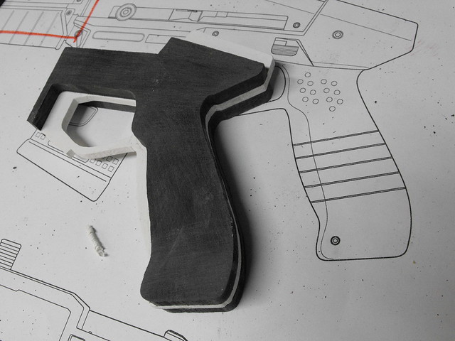
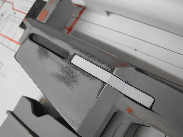
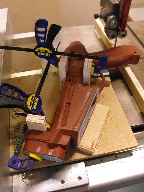
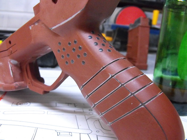
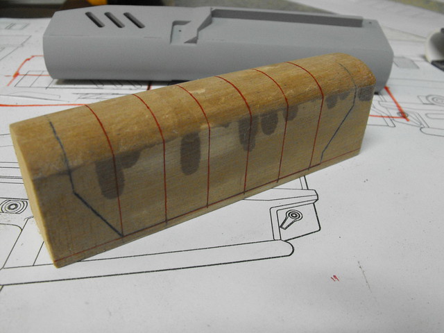
The grip was something a bit trickier to tackle. In the concept art, the grip has five shallow recessed lines which go around the entire perimeter of the handle. I decided the best way to get this look accurate would be to chop the grip into 6 sections and glue them back together with thin spacers placed in between them. I started by making a jig which would hold the gun steady against the fence of my bandsaw so I could make each cut at an identical angle.
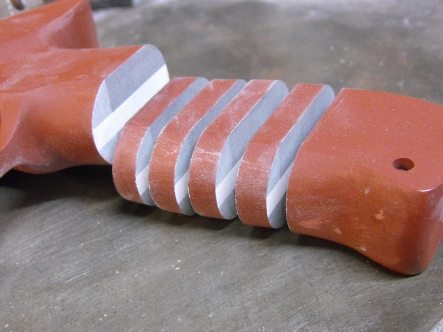
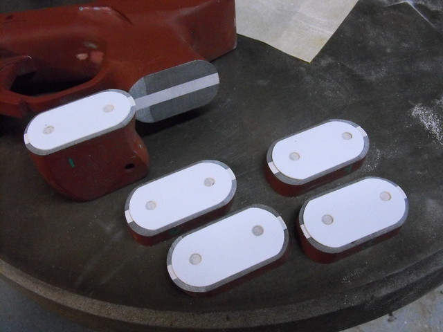
By moving the fence in equal intervals while cutting the handle, I ended up with 6 parts and 4 inserts of identical thickness. I affixed a piece of .040″ styrene to the top of each piece before gluing them all back together. Also in this shot are more scrapbooking accessories – these little blue dots were in a packet of “raindrop” stickers.
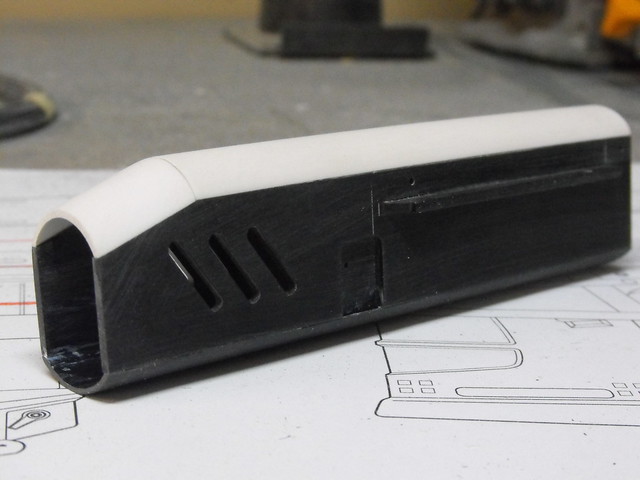
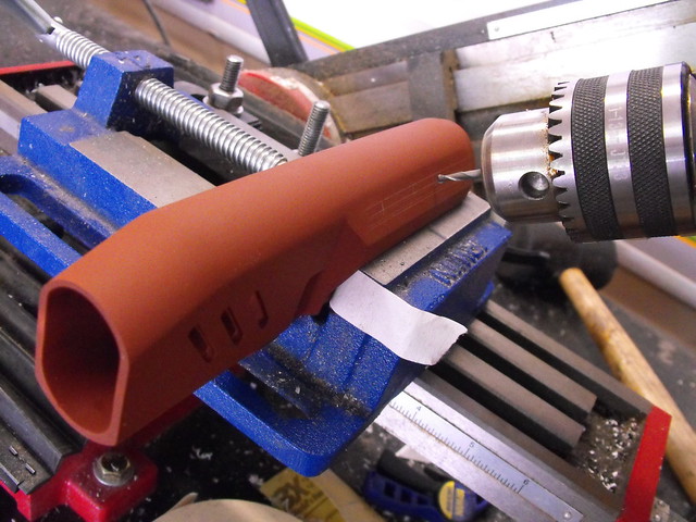
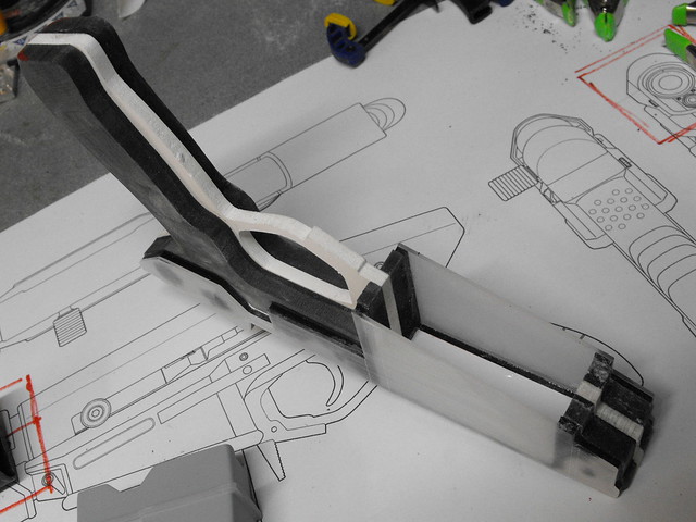
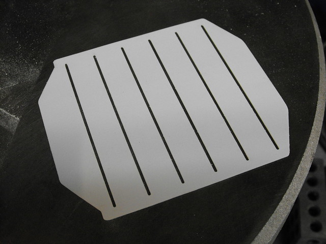
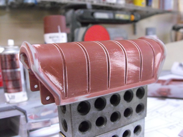
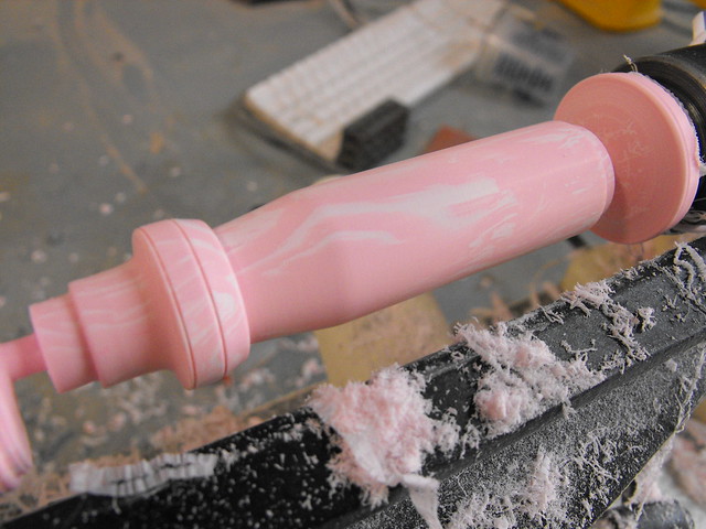
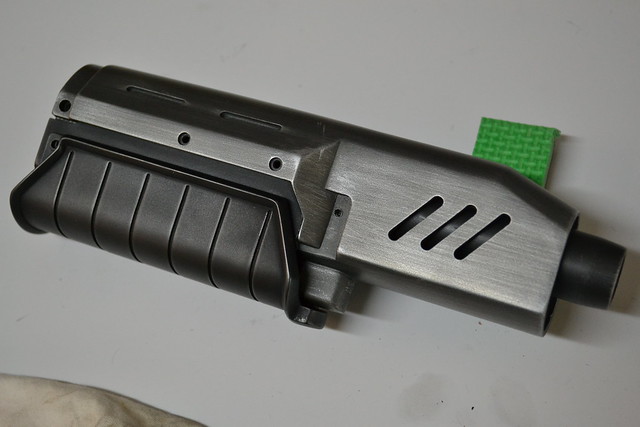
The forward grip was a bit of a tricky piece to get right. I actually made this part twice, since my first attempt was about .25″ too narrow. I started out with a wooden buck and heated a sheet of sintra over the form to get the base curved shape. A piece of .020″ styrene was then cut in the shape of the grip on a flat plane. This was then glued to the U-shaped sintra piece and sanded down to the edges.

There’s a sharp angled ridge that defines the outer edge of the grip. I started out by sculpting this roughly in apoxie sculpt. It might not look like it, but I took care to make the inner edge as even and straight as possible, since cleaning that up after the clay cured would be difficult.
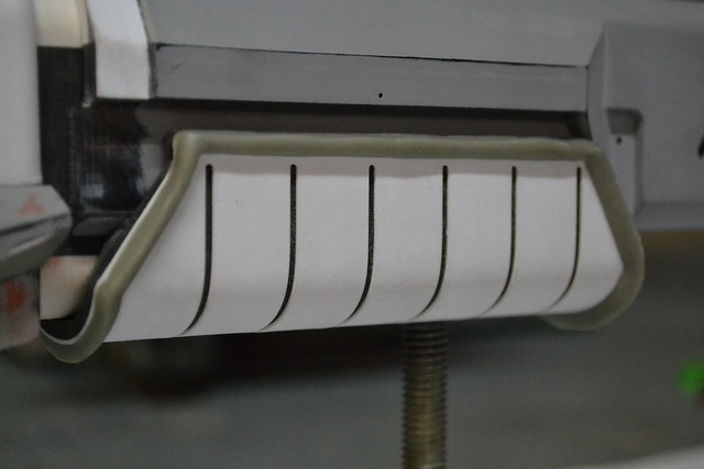
Here it is again after a lot of sanding and a few spots of filler.
A small semicircular detail was added to the front to act as a mounting point for the grip to the rest of the gun.
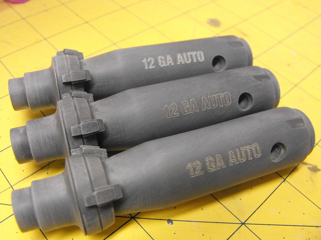
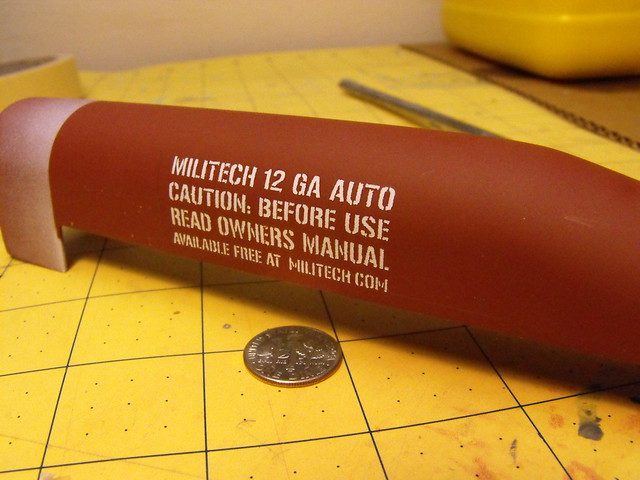
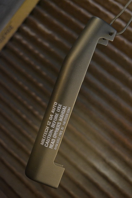
The bolt and shell were both turned on a lathe from blocks of urethane resin. The lettering on the bolt was laser etched into the surface.
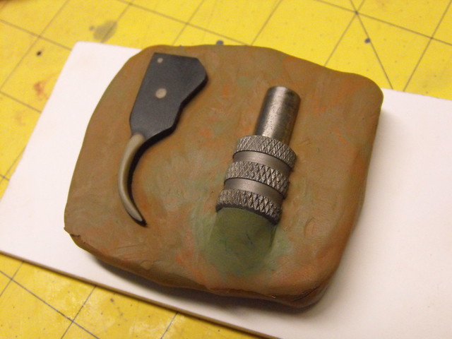
Smaller bits here – the trigger is a single piece of laser cut acrylic with apoxie sculpt detailing for the wider paddle shape. The bolt lever is actually a 3/8″ nut insert with a piece of stainless steel rod epoxied into place. This shot shows both parts embedded in clay awaiting mold silicone.
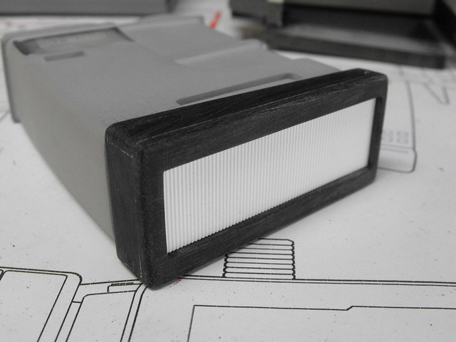
You can see the upper bolt shroud in this shot – this is just a mock up part, but the vacuum form buck I showed earlier was used to make copies in styrene and ABS.
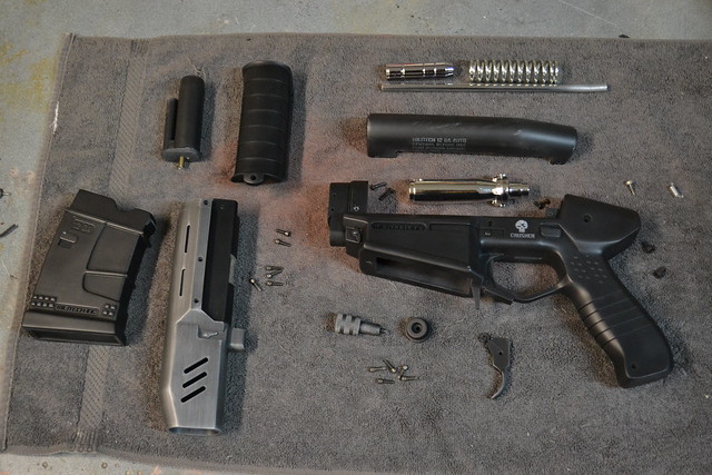
Here’s the whole kit ready for mold making!
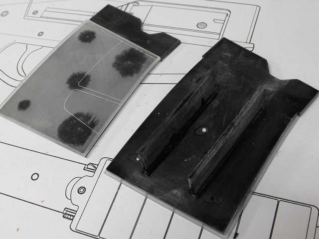
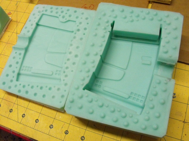
Each part was half embedded in clay and surrounded with mold walls. All parts were block molded, since this is the fastest process and easiest to do in a short timeframe. I used Smooth-On’s Mold Max 40 silicone for most of the parts.
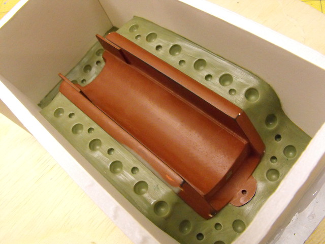
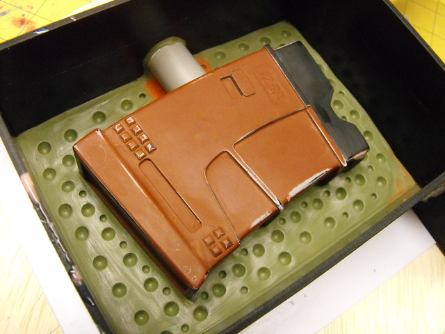
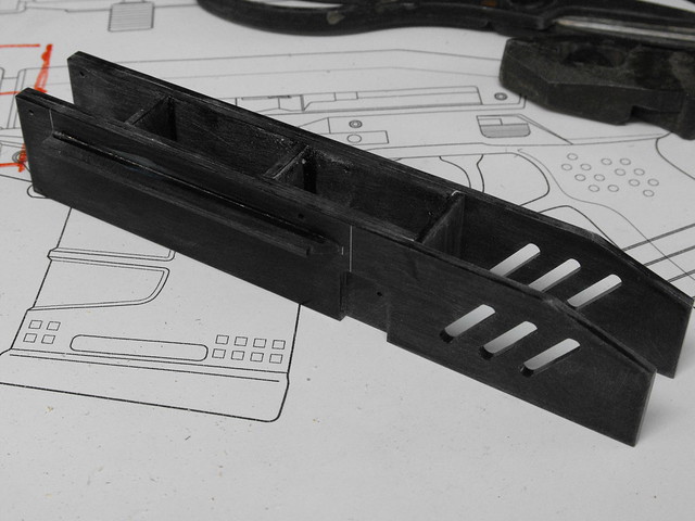
The receiver and barrel shroud each needed to have a third section added to the block molds to create the cavities for the magazine and barrel. I left clay plugs around these areas and capped off the openings with styrene and masking tape in order to keep silicone from flowing into these areas and locking the parts in place.
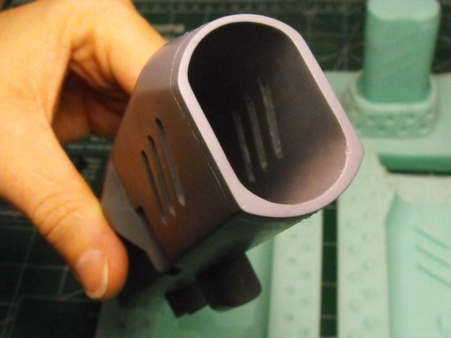
These three shots illustrate the cavity of the barrel shroud. The upper thin plug ensures the forward section of the part is cast hollow. A similar plug allows the magazine well in the receiver to be cast in a similar way.
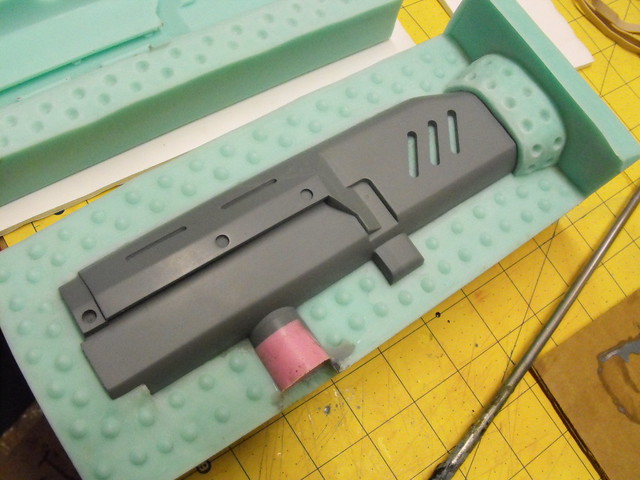
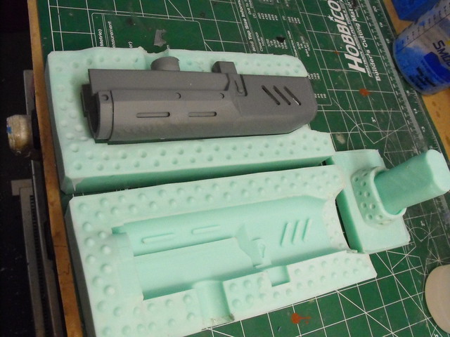
A few shots of finished molds and some cast parts.
The stenciling on the side of the bolt shroud was done by laser cutting masking tape then airbrushing acrylic paint onto the stencil. I’ve since discovered a better material for this (stencil vinyl, duh) but the results here were still quite good!
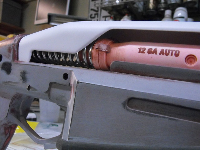
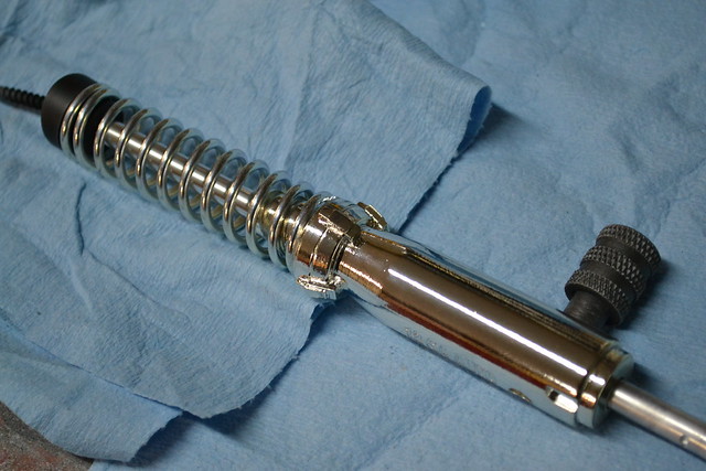
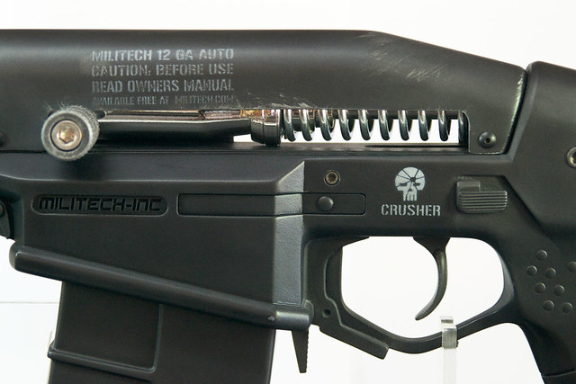
Here’s a shot of the inner guts of the bolt assembly. The large spring was sourced though McMaster-Carr and an aluminum rod makes sure everything stays on center. This rod also extends forward into the barrel shroud, giving the piece more rigidity.
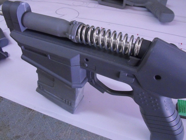
A slot was milled into the main body for the trigger, which articulates on a pivot bolt and is returned to place with a small spring.


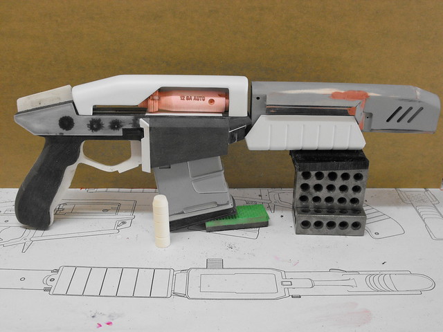
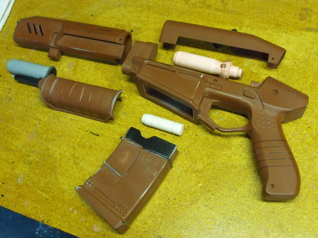
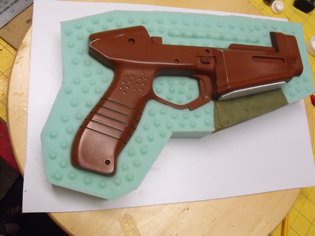
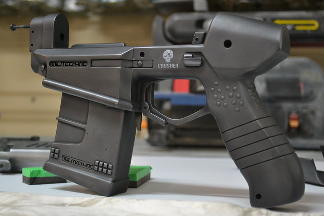
Here’s all of the cast parts assembled – no glue is used, all pieces fit together with screws only!
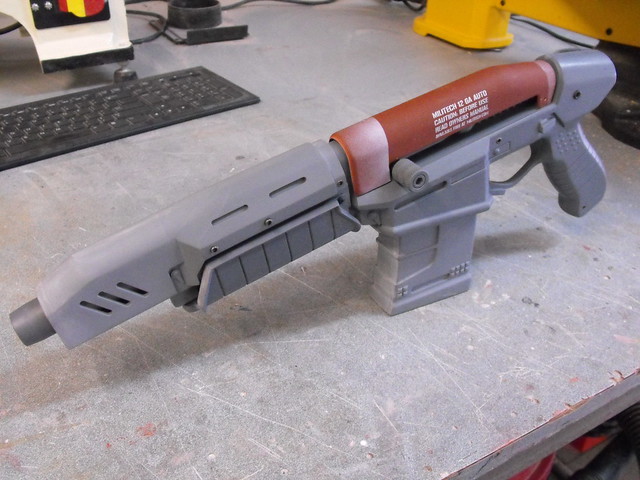
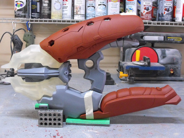
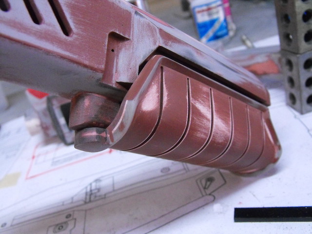
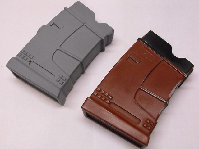
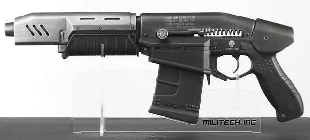
A note I got from CD Projekt RED outlined the specific materials for each part of the gun, so I took great care in deciding on paint and finishing coats. The main body, forward grip and magazine were supposed to be a black polymer plastic, so each was painted with flat black enamel.

The bolt shroud needed to simulate scratched steel. I used a base coat of Testor’s “Gunmetal” Metalizer for the initial color.
The barrel shroud was supposed to be brushed aluminum on the upper section and polymer on the lower. This first got a base coat of flat black, then a second coat (after masking) of bright aluminum lacquer, followed by a thin coat of gunmetal lacquer. After allowing the gunmetal coat to cure overnight, 000 steel wool was used to gently create brush marks across the surface, bringing out the coat of aluminum lacquer underneath.
I wanted a bit more depth for the polymer parts than just flat black, and I recalled a build over at the Replica Prop Forum where a builder who goes by Matsuo used graphite to highlight areas on his gun projects. I started out just raking a pencil across some of the higher parts of the gun, which gave subtle highlights, but not quite enough. I rubbed an old piece of cotton cloth with a stick of HB graphite then wiped down the entire surface of the gun body, grip and magazine. The result was perfect – it dulls a bit with clearcoat, but I’m very pleased with the technique.
Most of the weathering on this piece was done to the upper bolt shroud, since it was supposed to be scratched steel. The remainder of the parts only got a very light black wash of acrylic to accent seam lines and cavities before clearcoat.
My friends over at Creations n’ Chrome were able to chrome plate the bolt and shells for me, matching very well to the spring and polished aluminum rod.
The whole kit – screws and all – ready for assembly!
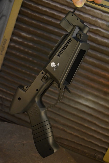
I made an acrylic display base with an inset logo for showcasing the gun. The Crusher has already been shown at E3 and will be heading to Gamescom shortly!
Make sure to check out the gallery for more completed shots of the piece in higher resolution. As always, there are more progress photos available on my Flickr page for those interested.
Thanks for reading!

Bird Splicer Mask, Bioshock
I suppose it’s no secret that I’m a pretty big Bioshock fan. Infinite is just around the corner and I’m really looking forward to all the props that game will open up to me, but before that there was one thing still in Rapture I wanted to have a crack at building.If you’re like me and want to take a pass at making your own Splicer mask, I sell raw styrene copies of the finished mask in my store, ready for trimming and paint!
Splicers in Bioshock wear once-festive party masks that have been smattered with blood and cracked with abuse during their time in Rapture. My favorite design has always been the bird splicer masks, so when I got a commission for one earlier this year, I jumped on it.
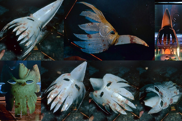
Gathering reference was a bit tricky here. I don’t have the PC version of the game and though someone unfolded a pepakura model of the mask some time ago, it has since disappeared after the demise of Megaupload. Nothing to do then but fire up the game! One of my save files happened to be very convenient as Jack was wearing the Big Daddy suit and the splicers would ignore him. Perfect for reference. I found a bird splicer, dispatched the poor fellow, then used the “Telekinesis” plasmid to get about a hundred different views of the mask.
I used these references to put together a set of blueprints, then commenced building.
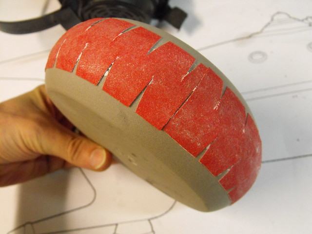
The plan was to sculpt a base mask form that would be used as a vacuum forming buck. This would be split into two parts, with the beak being separate from the rest of the mask. I began by making a series of MDF sliced sections, then filling the cavities with foam and sanding them to a rough shape.
The eye area of the mask was actually pirated from a glass wig head in my shop. I took a scrap chunk of 0.1″ styrene and heated it over the form, pressing it into shape as it cooled. The resulting piece was trimmed down and glued to the MDF and foam frame. Bondo was then used to blend the styrene into the foam panels and make the entire dome more uniform.

This looked very, very strange.
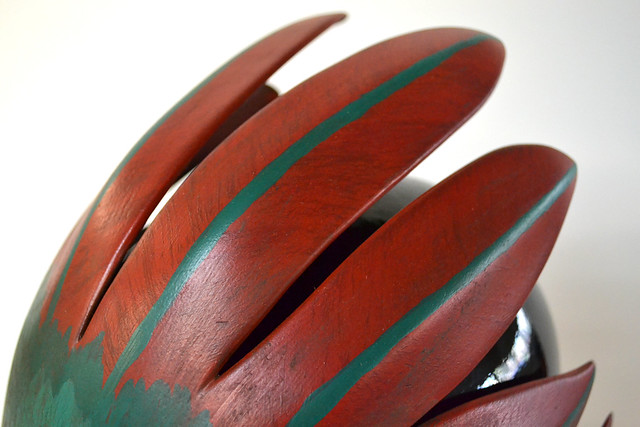
Several passes with Apoxie Sculpt followed this step. I began by roughly blocking out the feathers and filling in the eye areas to sit further out from the mask. The mounting lip for the beak and bridge of the nose was also extended and filled in here.
Primer and sanding followed, and then some filler putty.

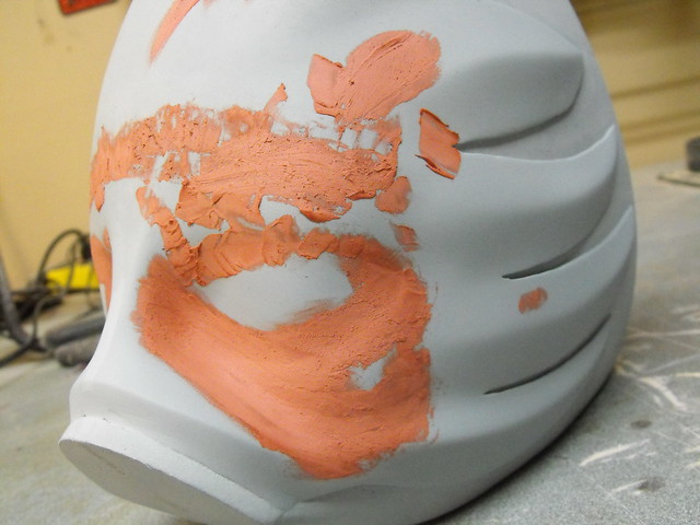
The last detail needed were a couple of raised edges around the eyes. These were also done with Apoxie Sculpt, after a lot of measuring and cutting out a paper template to use in order to make both eye holes symmetrical.

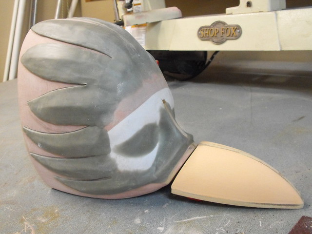
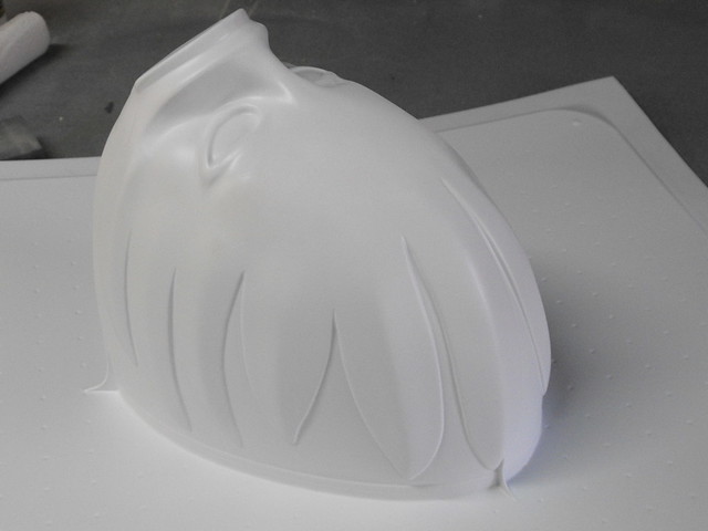
The first pull was done in .040″ styrene plastic, which proved to be too thin after stretching over the large form. There was also significant webbing when trying to do both pieces at once, so I had to separate the beak and the face sections.

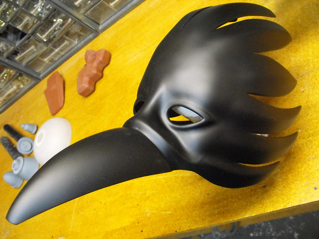
The second pass, done in .060″ plastic, was much more successful.
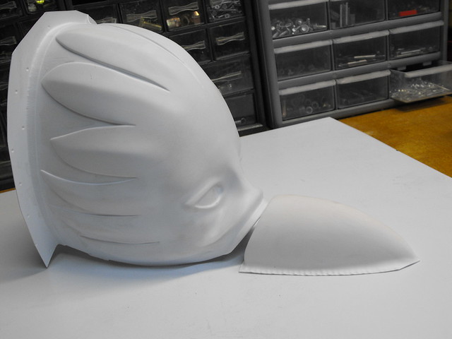
After the parts were trimmed, the beak was taped into place and secured in the corners with small spring clamps. Superglue was used to bond the two styrene segments together permanently.

A few passes of primer and a fine grit sanding sponge were used to prep the masks for paint. At this point my client requested a second mask, so I pulled another copy and assembled it as well.

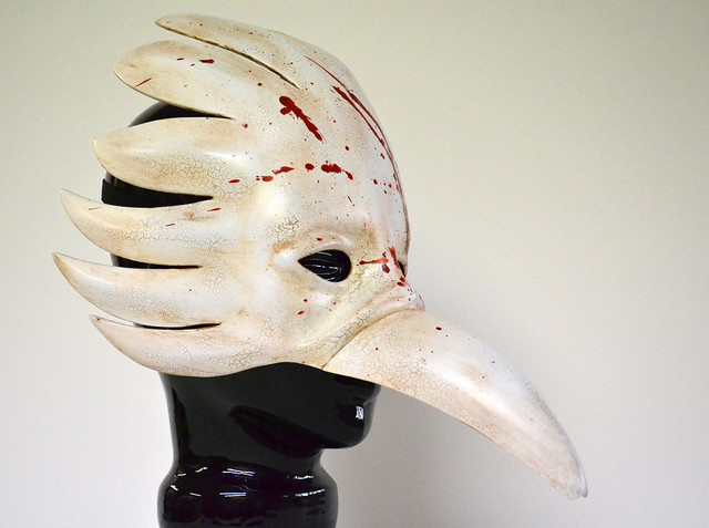
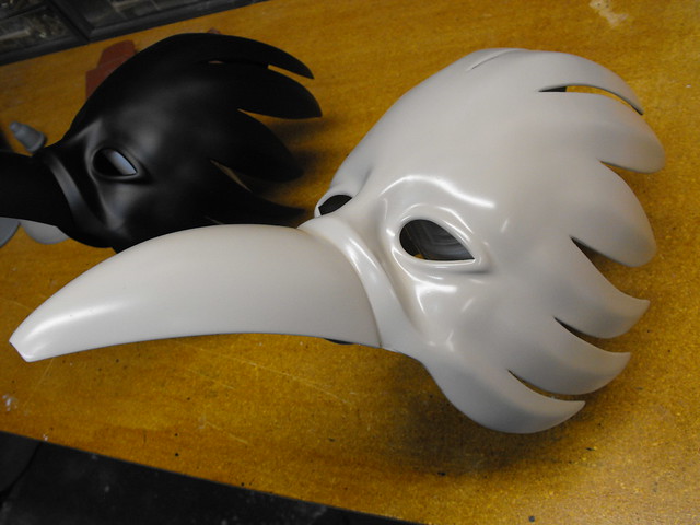
The two finished masks will have very different paint jobs, so they each got a different base coat color. One is a light tan eggshell, and the other is (obviously) satin black.
I went through a LOT of test pieces before settling on this finish for the masks. My client wanted a look that emulated cracked porcelain on the white mask. I had about a dozen test scraps before landing on this. The base coat is the tan seen in the above shot, which was then brushed over with Elmer’s white glue. This wasn’t watered down, but it was brushed on pretty thin – enough to make the surface appear “wet” but not enough where you could see the white tint of the glue. While the glue cured, thinned acrylic paint was airbrushed over the entire part. I found that the cheaper the paint was the better it cracked – I imagine this has to do a lot with how flexible the cured acrylic is. The stuff I used was Blick brand white paint, the kind you’d find in an elementary school. Cheap!
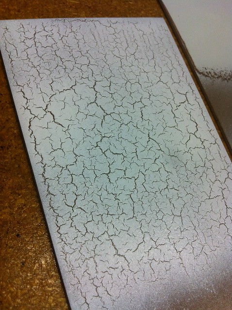
By selectively applying the paint to certain areas on the mask, I was able to get cracks to show up in some places but not others. The finish on the white mask was perfect.

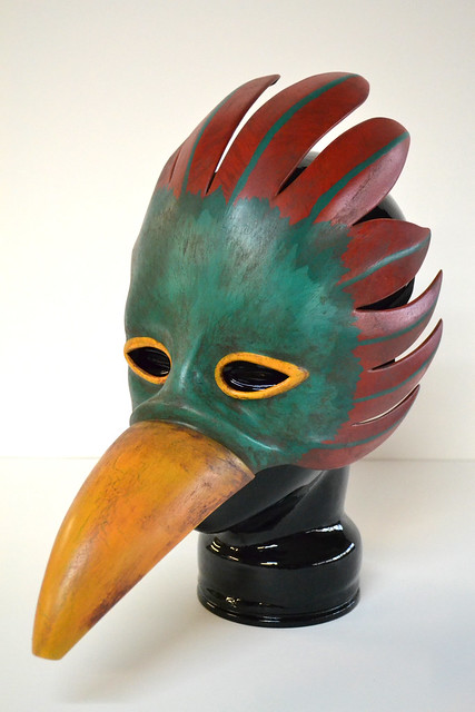
The second mask required a bit more prep. There are only 4 masks like this in Bioshock, worn by the four Splicers that Sander Cohen sends you kill and photograph in the “Fort Frolic” section of the game. These have red feathers, green feathered paint around the eyes, a yellow beak, and yellow eye accents.
First, the feathers were airbrushed red and allowed to cure, then I used a drybrush technique to streak paint across these parts in a feather-like pattern.
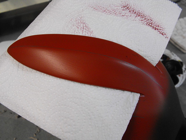
The green areas were painted with a base of Elmers glue to get them to crack a bit, but I used a thin brush to get a small feather texture to the paint. Green was also used for the quills on the red feathers.
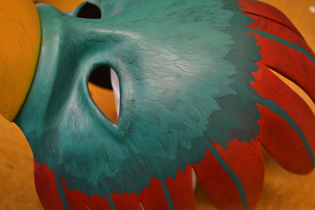
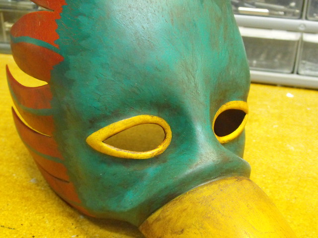
Lastly, the beak was airbrushed yellow and the areas around the eyes were accented with yellow rings. This was all done with acrylic paint.

In order to protect these base layers, the acrylic paint was sealed with clearcoat at this stage before weathering. I wanted to make sure that rubbing the grime coats into the cracks and crevices of the masks didn’t disturb all the work I’d done already.
The finishing touch for the Fort Frolic mask was a few passes of dirt and grime, once again done in acrylic paint. I used a damp paper towel to streak the paint across and remove dirt in raised areas while depositing it into recesses.
The white mask got a similar coat of grime before the really fun part…
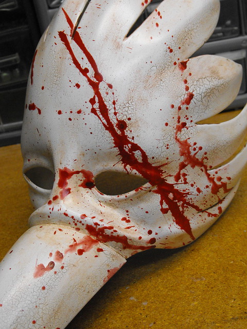
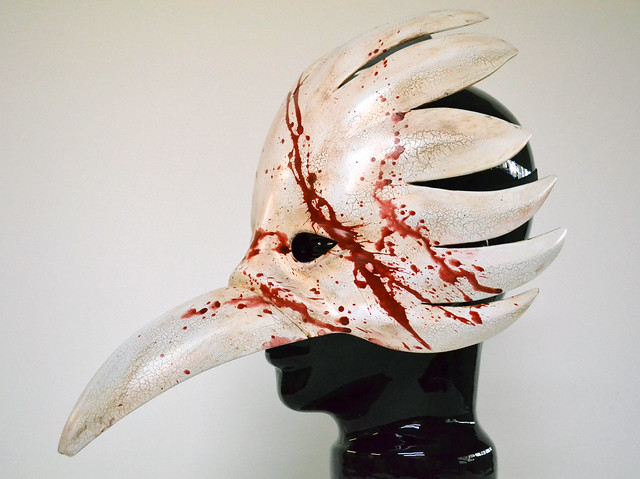
…blood splatters! It’s been a while since I got to do a really fun splat of blood, and this one turned out wonderfully. After the acrylic weathering cured, both masks got another pass of clearcoat and an elastic strap was added so they could be worn.

Here are some shots of the finished pieces – if you want to see more photos of them in higher resolution, check them out the gallery.


Thanks for reading!


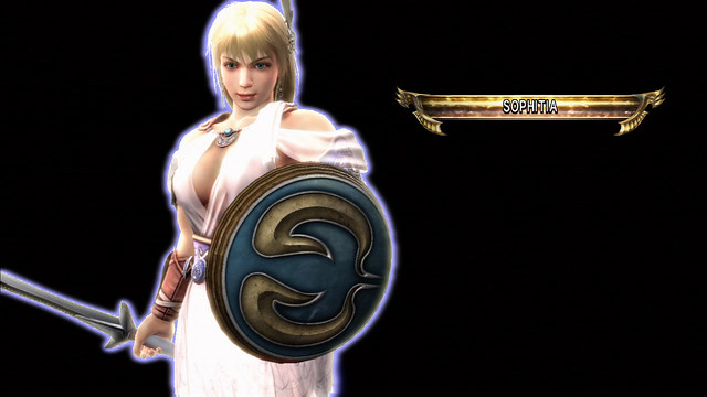
Sophitia’s Elk Shield, Soul Calibur IV
I’m a bit behind on updates – there are still two full armor costumes from 2012 that I haven’t written up yet! That said, here’s a more recent project with a bit shorter (hah!) write-up that I hope will tide people over in the meantime while I chip away at my backlog.
Sophitia’s Elk Shield. I built this, and the sword to go with it, for Jessica Nigri as part of an upcoming costume. While I’ve done something very similar to this before, I thought I could make several improvements to the project to make it both lighter as well as sturdier and more interesting dimensionally.
Let’s begin!
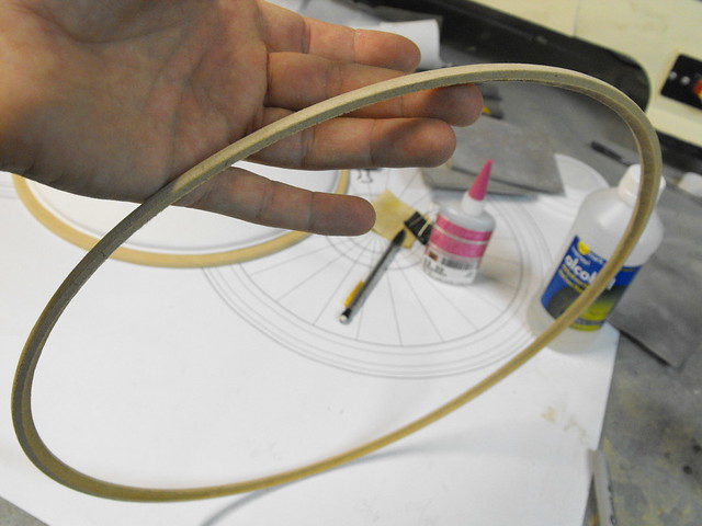
As always, blueprints! If you’re interested I do have these available in vector based PDF available for download (as well as all my other blueprints) in my store. The shield worked out to be fairly small, but it is a buckler after all.

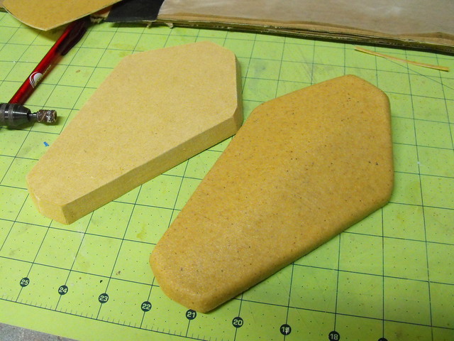
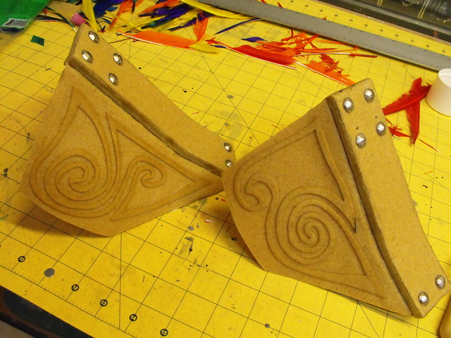
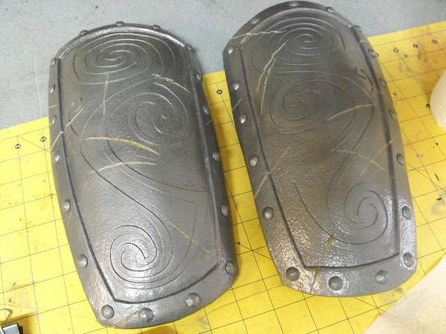
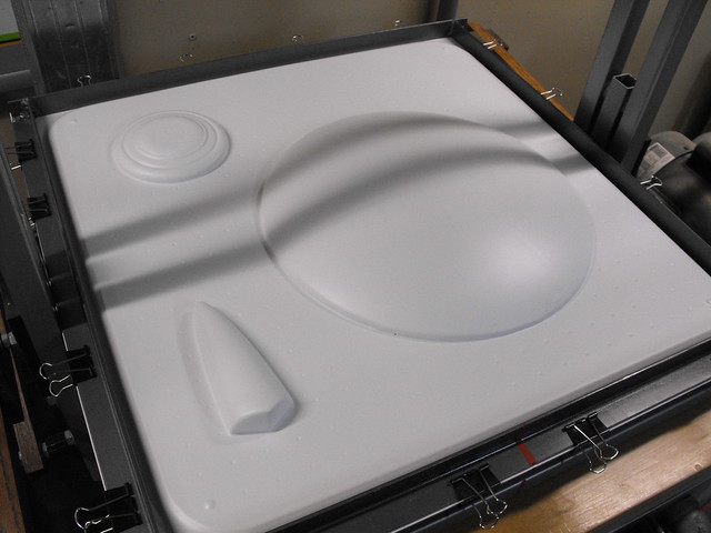
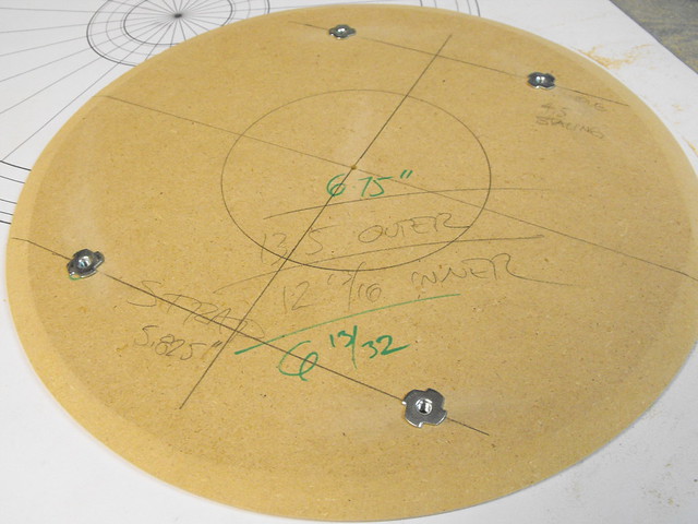
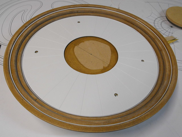
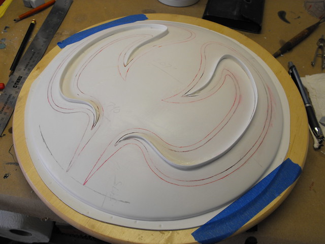
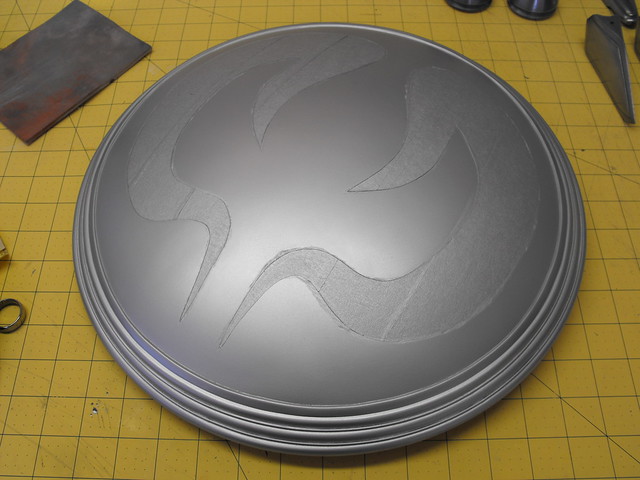
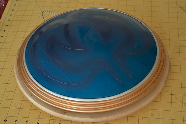
The biggest deviation between this and my earlier shield for Cassandra will be the rounded dome. Cassandra’s shield is a foam block sanded to shape and resined over, but Sophitia’s will be hollow styrene. To start off, an MDF platform and raised spines were cut and glued together.
These were filled with blocks of urethane tooling board, then cut and sanded down to a rough dome shape.


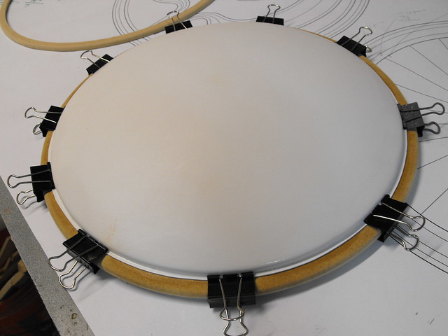
Bondo was used to fill in several of the gaps and smooth out the surface overall. Once it was sufficiently rounded and even, the buck was vacuum formed from .060″ styrene to make a hollow shell.

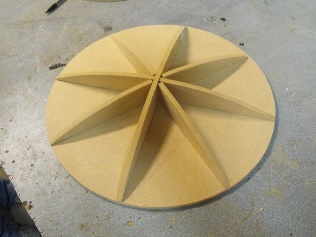
The rings on the outside of the shield are stacked MDF circles. The initial shapes were trimmed on the outer edge with my bandsaw, and along the inner edge with my scroll saw. I made a homebrew circle cutting device for this task; essentially a board with a nail in it. By drilling a hole in the center point of the circle you want cut then pivoting the MDF around this nail, you get a perfect circle from a regular saw.


Here’s all the rings trimmed out, and stacked on the base of the shield. These were all eventually also passed through my table router in order to round off the edges.
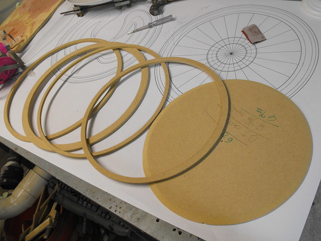
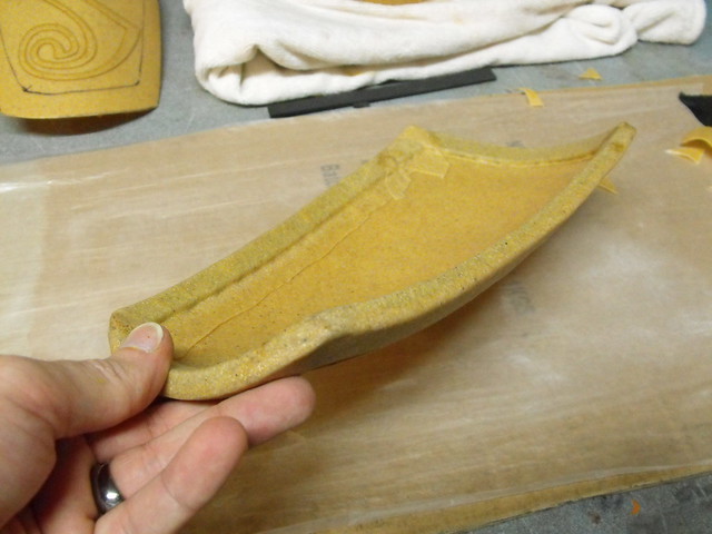
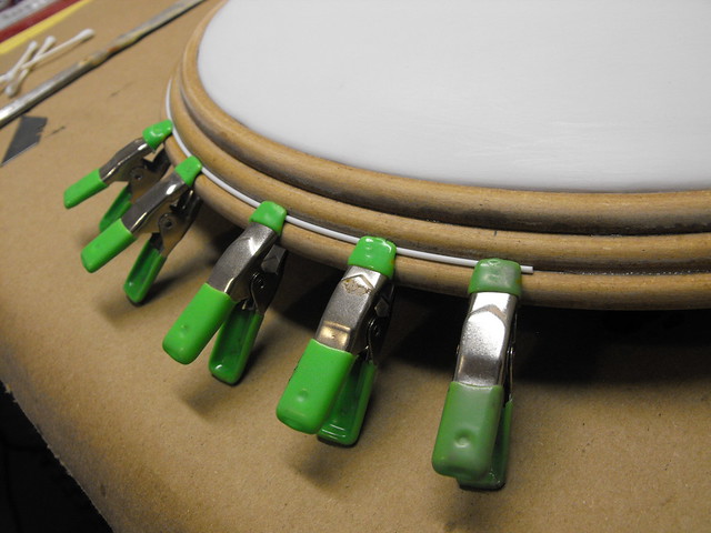
One very thin ring had to be cut to hide the seam of the styrene dome. This piece is 1/4″ thick and only 3/16″ wide, with a rounded outer edge and a concave inner edge. A little scary trimming this on my table router, but it worked out in the end!
The main baseplate of the shield had T-nuts inserted which will provide mounting points for the strap and handle later on.
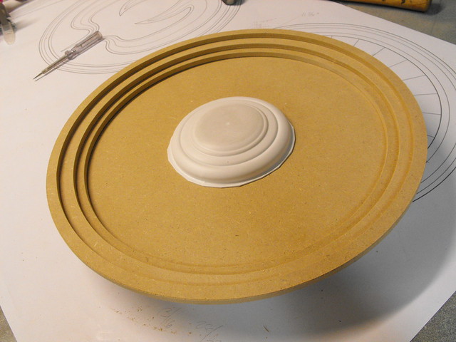
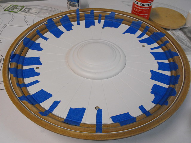
The dome and all the boards were glued together with gap filling superglue and allowed to cure.
For the detail strip between the levels on the rings, I used round styrene bars in .040″ and .060″ diameter. These were glued on one small section at a time to make sure they were flush and even. The process was repeated for the inside as well.
On the backside, a sheet of styrene was scored with an engraving tool, drilled to match the mounting screw holes, then glued into place. It wasn’t possible to get small spring clamps to hold the styrene bar in place here, so pieces were taped down while gluing. If the center puck looks familiar, I re-used the vacform buck from the Cassandra shield project as they’re identical in-game.
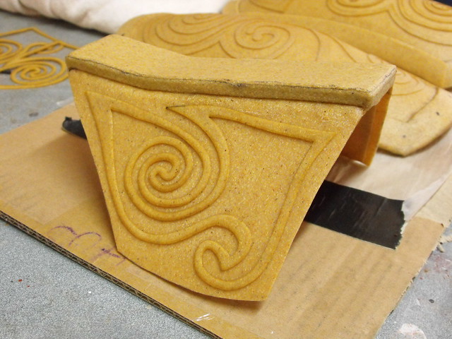
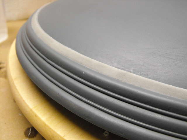
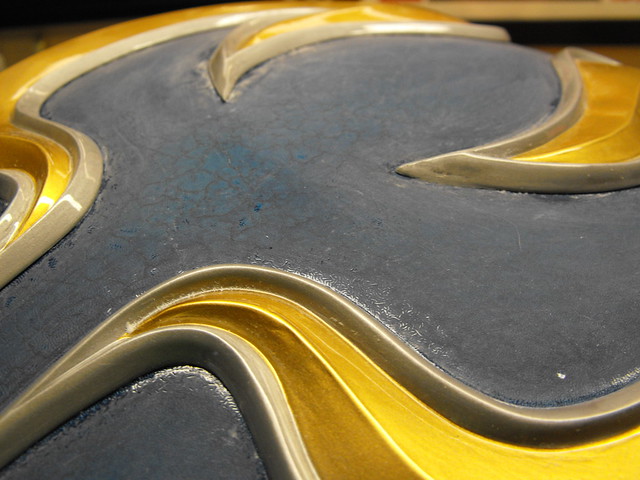
The last ring detail was a flat strip that ran the circumference of the shield right on the styrene dome. This was sculpted from Apoxie Sculpt then sanded even after curing.
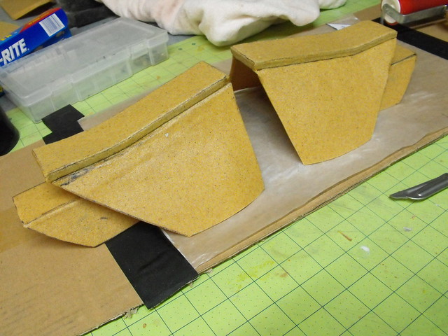
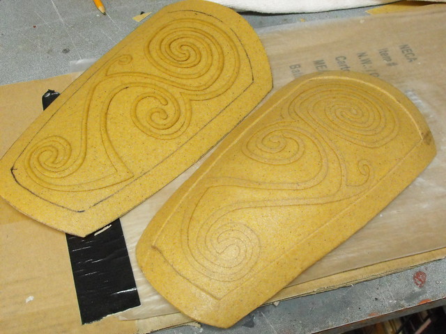
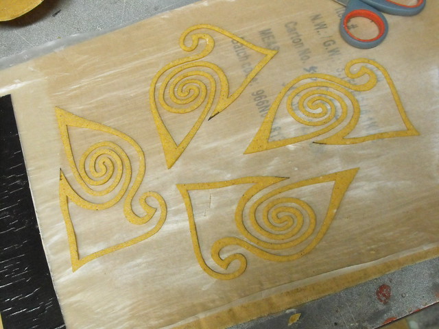
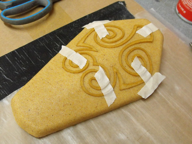
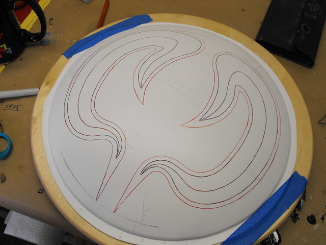
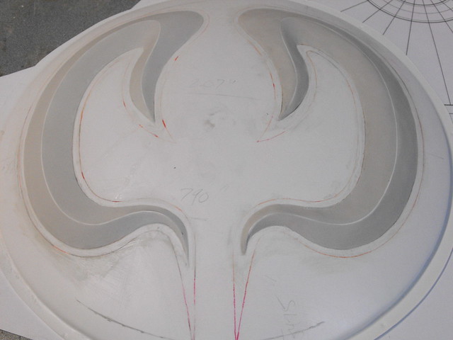
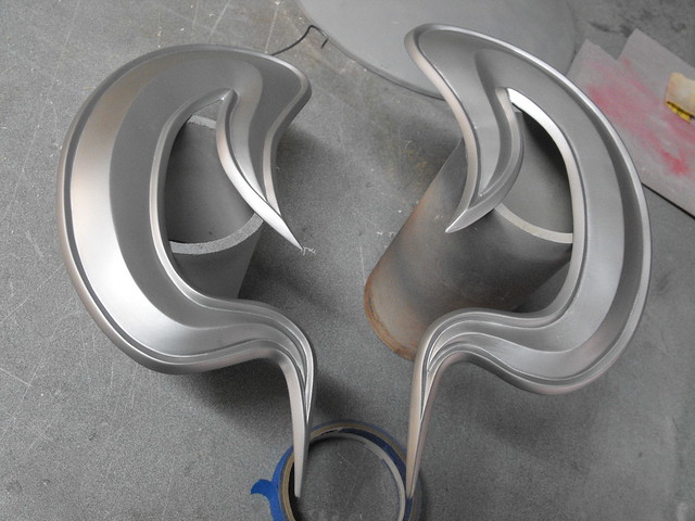
The “elk horns” on the front of the shield were transferred to a second vacuum formed dome by trimming out the pattern to lay flush over the curved surface, then traced. A thin strip of styrene was used to mark the center “spine” of these parts before sculpting.

I tried out a new material this time in favor of saving some weight on the finished piece. The stuff shown here is Smooth-On’s “Free Form Air” epoxy. While it is extremely lightweight and dries fairly hard, it is nowhere near as nice to sculpt with as Apoxie Sculpt. The uncured clay sticks very badly to skin and sculpting tools, and its far too easy to damage the surface with even a light touch while sculpting. It also stinks to high hell.
After struggling with this stuff, I switched back to Apoxie Sculpt for the outer trim around the elk horns. After this cured, both pieces were cut out from the styrene dome and sanded to shape.
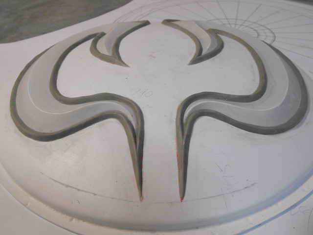

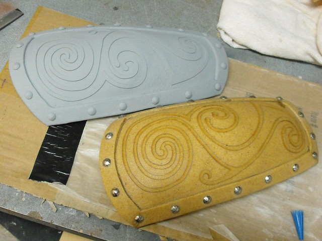
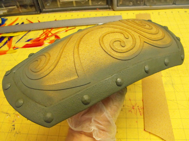
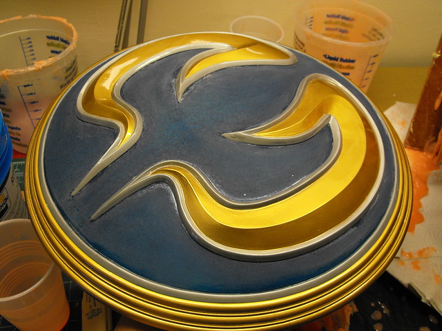
Last stages before paint!
I had such an elaborate plan for this… and it all kind of went to hell. Let’s watch, shall we?
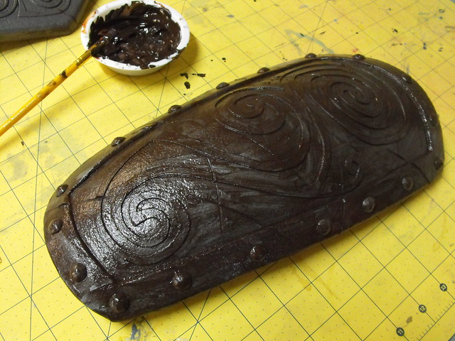
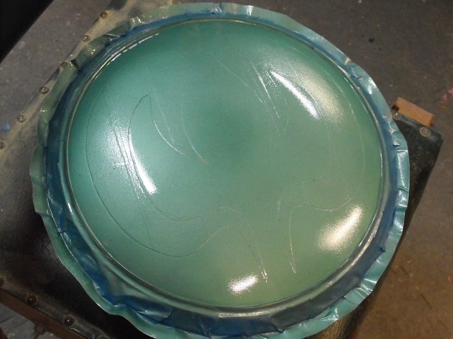
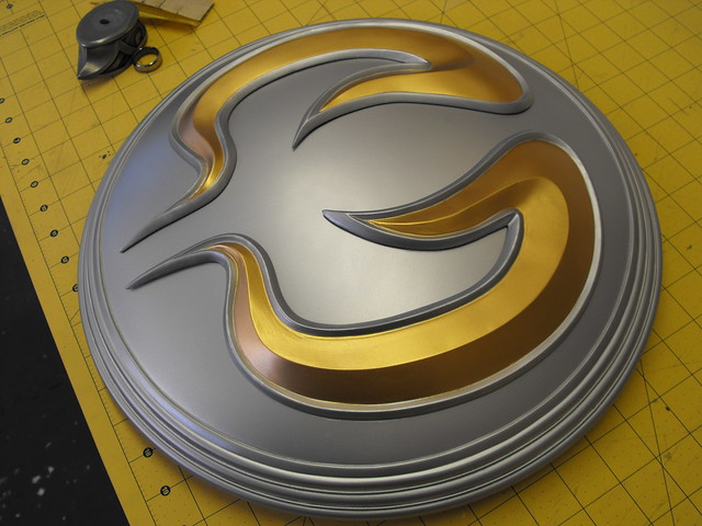
First off, the whole shield was base coated with Testor’s Metallic silver enamel. Actually, from here on out, all the paint unless noted is Testor’s Enamel. The elk horn areas were masked off so there would only leave bare styrene in place after the paint was finished. This would give me a plastic surface to glue to later. You never want to glue onto paint because that’s all the glue will stick to – the very weak adhesion between the paint and your project is what you’re actually relying on. Always make sure to scrape away paint before gluing!
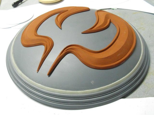
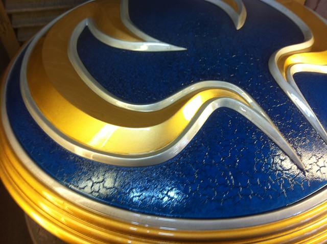
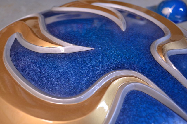
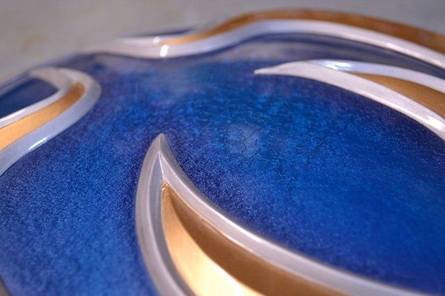
After masking off the shield rim, the center of the shield began quite a journey. Starting off with metallic teal green…
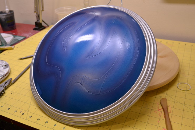
…then a few coats of translucent metallic blue…
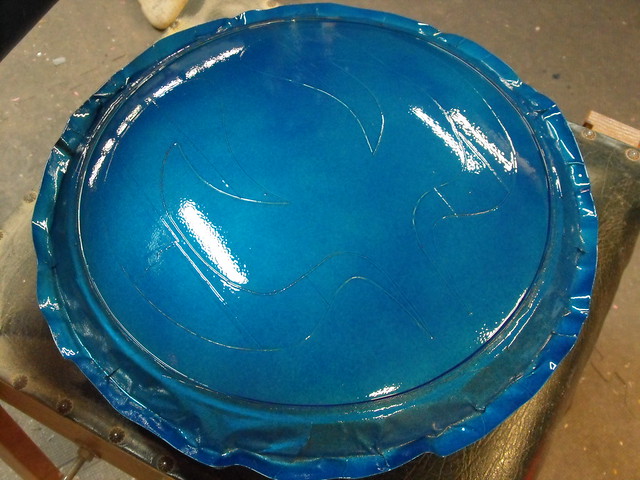
This paint texture was really quite pretty in person – the hue and metallic pigments shift a lot in person and give the shield a lot of depth. The perimeter of the elk horns were airbrushed on with more Testor’s Enamel and enamel airbrush medium. Keep that airbrush medium in mind, it’s going to be important in a second. In the photo below the shield looks very very blue – this thing played hell with my cameras (I use a mixture of 4 different cameras when documenting my work) and it looked completely different from shot to shot.
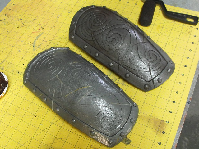
The front of the shield is actually gold (and changes to silver along the outer edge without any sort of seam line at all) so the blue area and the back of the shield were masked off while the outer rim was painted gold.
While all this was happening, the elk horns were also painted silver, then masked off and painted gold in the center.
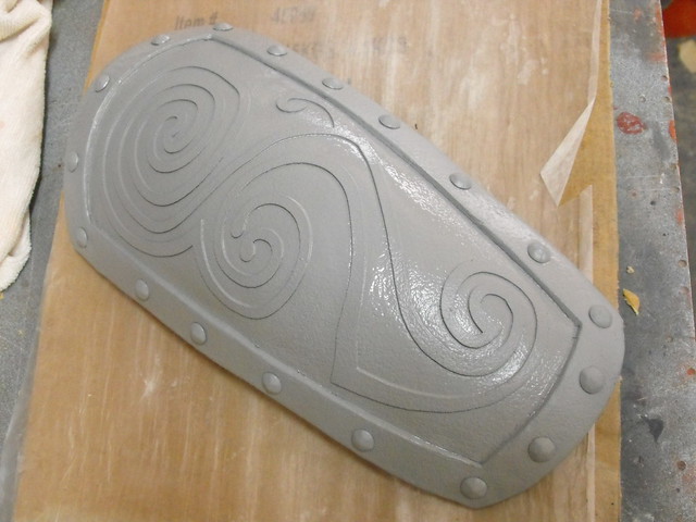
After allowing everything to cure for a full week (and each coat of paint was given 4 days cure time between layers) the shield was assembled! I gave the entire thing a beautiful coat of 2K Urethane clear…

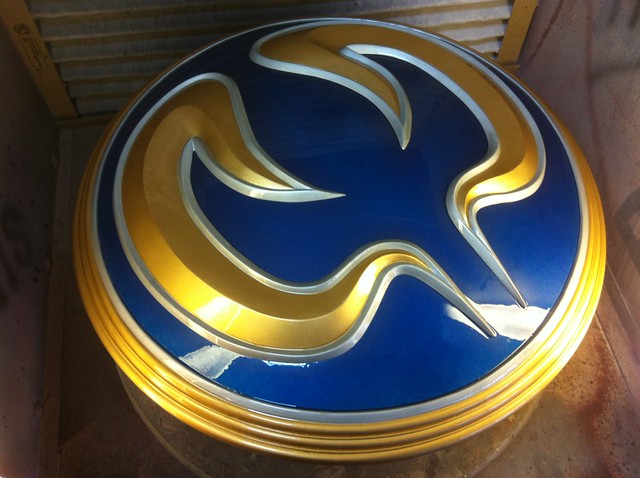
…and 2 hours later it gave me a heart attack. This photo is slightly out of focus; I believe my hands were shaking as I took it.
The 2K Urethane clear had been tested on all of the surfaces prior to this numerous times, but I had never tried it over the Testor’s Enamel Airbrush medium before. All of the cracking only took place where that specific thinned paint was used.
Knowing that now helps me in the future, but at the time I had to choose whether to chisel off the elk horns (thus destroying them in the process and probably damaging the dome as well) and sanding the whole thing back down to nothing, or attempt to salvage this debacle.
I decided to salvage it. The clearcoat was a rock at this point and all reaction had stopped, so I loaded the entire shield up with clear. By the end of things, there was probably 1/32″ of solid urethane clear on this thing. After a few days of curing, I started on the surface with 400 grit wet sandpaper and some soapy water.
After about 5 hours of sanding, I had gone through 400, 600, 1000, and 2000 grit paper.
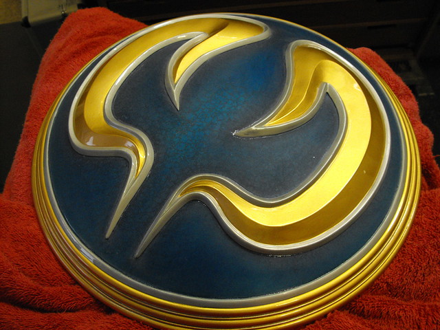
The next day, when my fingers had feeling again, I started buffing the newly smoothed surface. Starting with rubbing compound in medium cut then fine cut, followed by swirl remover, then three coats of tech wax. The results were… well, better than I could have ever hoped for.
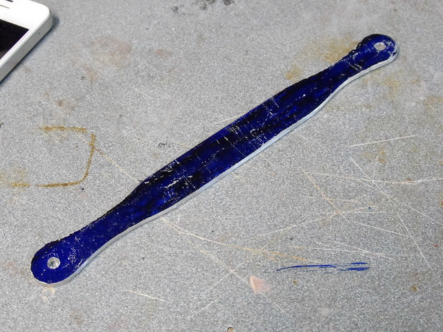
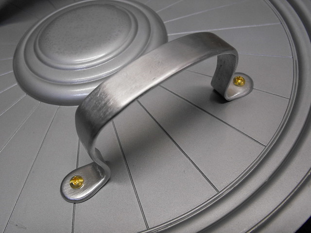
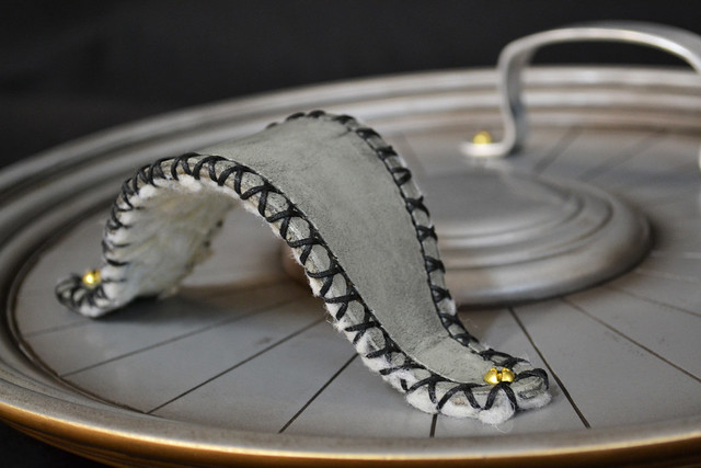
With the paint salvaged (WHEW) I turned back to the last remaining details. The grip was cut from a piece of bar stock aluminum, heated and bent to shape then sanded and rounded over with a dremel. The arm strap was done by my friend Cathy at God Save the Queen Fashions.

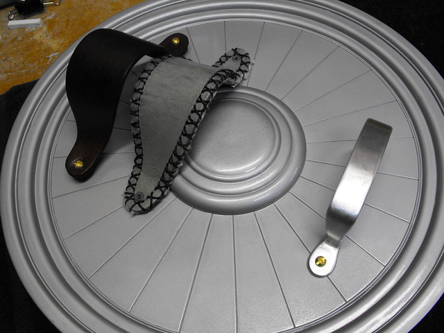
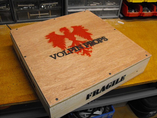
Check out that pro shipping crate! This is how all my replicas travel these days.

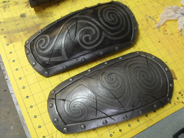
The last detail was some light grime and weathering in the seams of the shield and on the inside of the elk horns. This was mostly done with an airbrush, but pressed into the seams with a damp cloth as well.


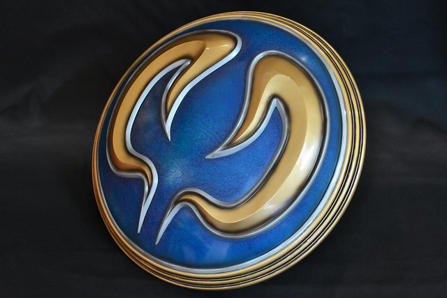
Here’s the finished shield, and a few shots of it next to the completed sword (write up coming soon!)
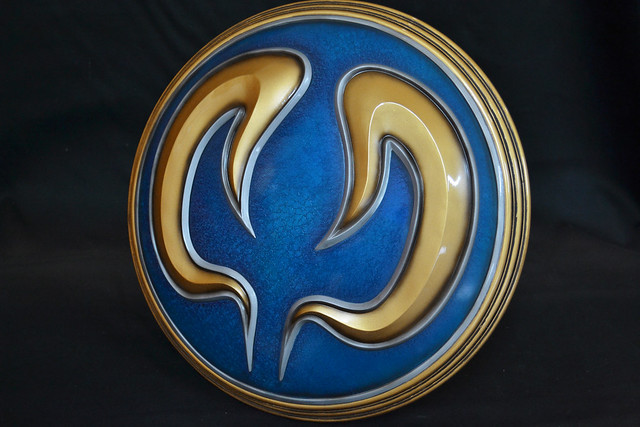
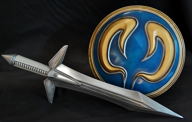
I’m very glad to have salvaged this paint job and lucky as hell it turned out as pretty as it did. I don’t want this to ever happen again, but it’s nice to know I can pull it out of the fire when it does. If you’d like to see higher resolution shots of the final piece, check them out in the gallery.

Thanks for reading!
