
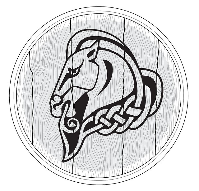
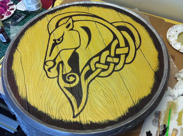
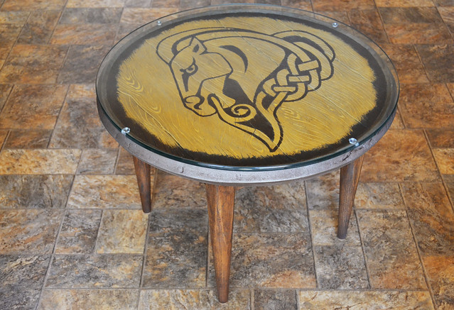
Shield of Whiterun, Skyrim
Since I made a set of Banded Iron Armor for my Dragon*Con 2012 costume, I decided I wanted to build a shield to go with the matched set. There are all sort of amazing and intricate shields in Skyrim, but unfortunately I only had about three days to make mine… so I chose something a bit simpler.

While a Whiterun Shield isn’t really something you’d carry around in game unless you wanted to show off the fact that you randomly killed some town guards, I had an affinity for Whiterun due to spending so much time there. Also, the celtic knots on the horse and the yellow color seemed to work well with the rest of the warmer earth tones in the armor.
I started out with some simple illustrator blueprints. There are a lot of good references for these shields on the Elder Scrolls wiki, though for some reason the shields all seem a bit oval shaped in a model viewer. For the sake of symmetry, I decided to make mine round, and 24″ in diameter.
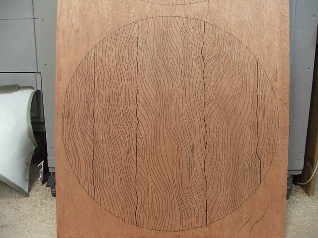
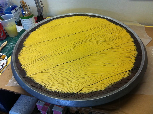
I wanted to use real wood that could take stain, but the piece also had to be as light as possible for costuming purposes. My plan was to sandwich a piece of polystyrene foam with a few sheets of luan board, then stain the wood the appropriate color. I started out by telling my shop monkey assistant to trace the blueprints I made onto wood panels. She did one and I did the second, and man was this mind numbing.
After the patterns were transferred, I cut out the wood “slats” on my scroll saw. The edges were then beveled with my dremel tool to better simulate the look of separate boards that were fitted together.

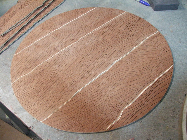
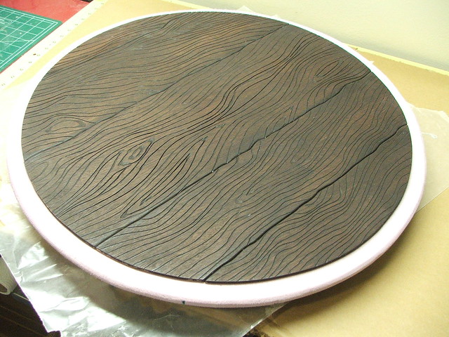
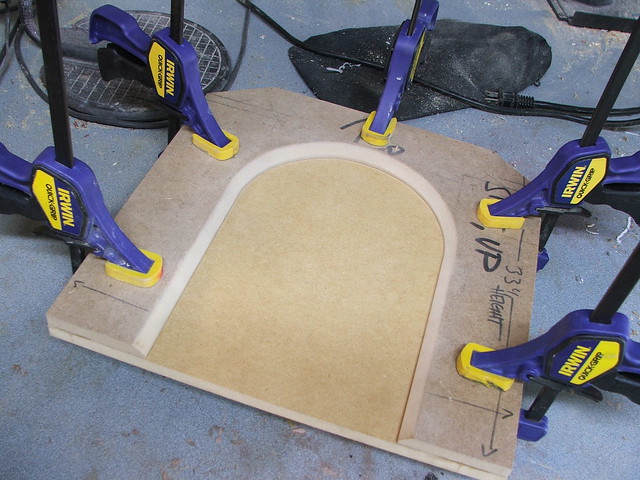
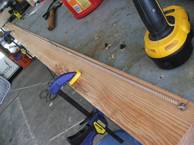
The natural woodgrain of the luan is very subtle, since it’s just sheet plywood. The actual shield looks like a much deeper grain that has been accentuated with age and inclement weather. I needed a way to carve a lot of very exaggerated wood grain texture into some thin wood paneling for a shield I’m working on. After trying out a couple methods with a router, hand files, and an engraving tool, it was looking like this segment of the project was going to take forever.
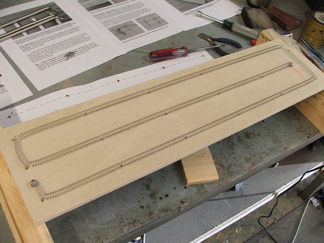
I figured what I needed was something like my scrollsaw, except with a dremel wheel attached to it. I pulled the blade from the saw, rigged my rotary tool with a clamp and a zip tie, and set up a few pieces of scrap board to set the table to the right height for the paneling. The patterns in this shot only took about 5 minutes, and I had the whole thing carved in a little over an hour.

After a little while the cutting wheel built up some dust and started leaving a burned edge behind it as it cut the patterns, but with the heavy stain the wood was going to get, this wasn’t too problematic.

For stain, I bought some dark Minwax and brushed on two thick coats, wiping off excess while it cured to let a little more of the natural wood texture through. This isn’t high end furniture work, but I think it turned out alright.
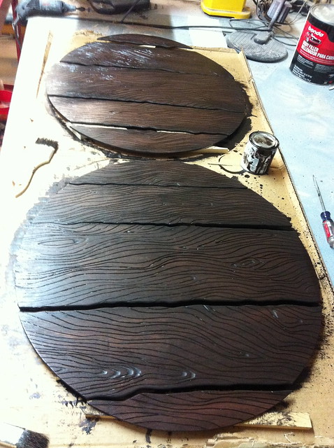
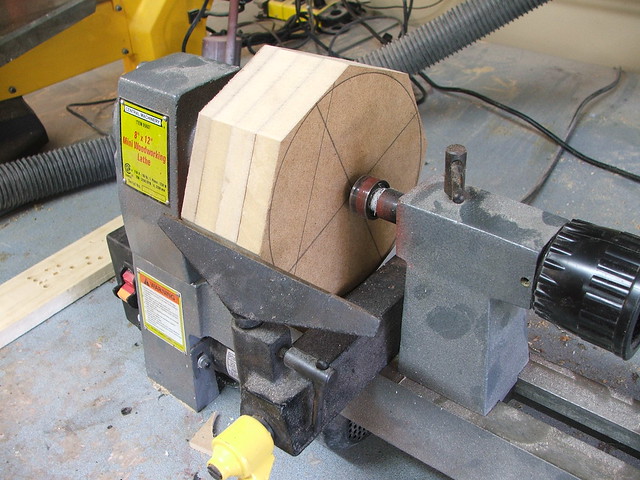
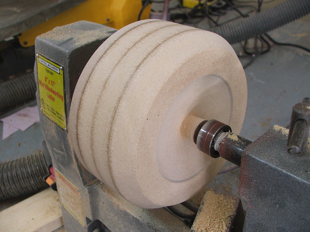
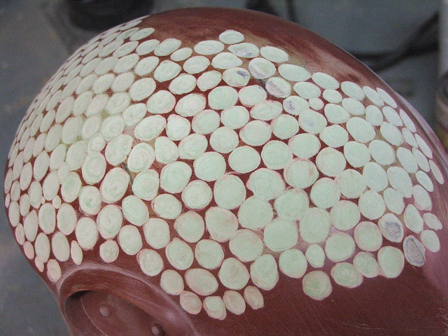
In order to make the shield thicker than the combined .25″ thickness of the luan panels, I cut out a 24″ circular disc of polystyrene foam to mount the pieces to.
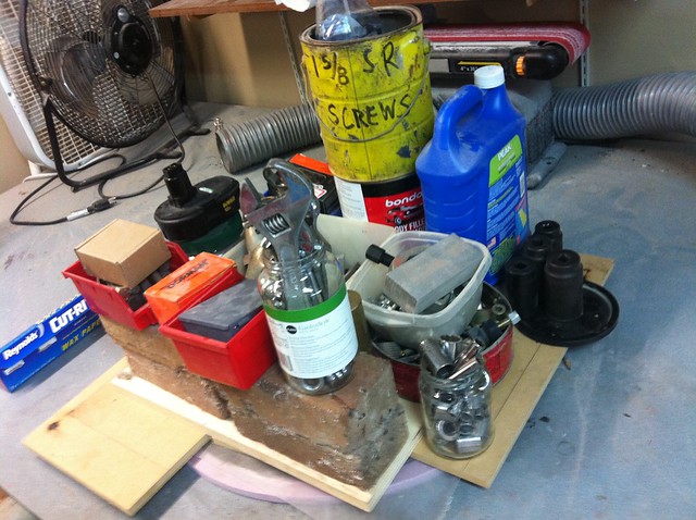
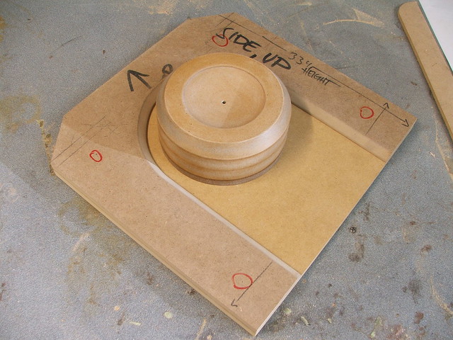
Each board was dampened with water, spread with gorilla glue and placed on top of the foam. I piled everything heavy from my shop on top of it to keep the boards in place while they cured overnight. I call this “Adequate Clamping Pressure”
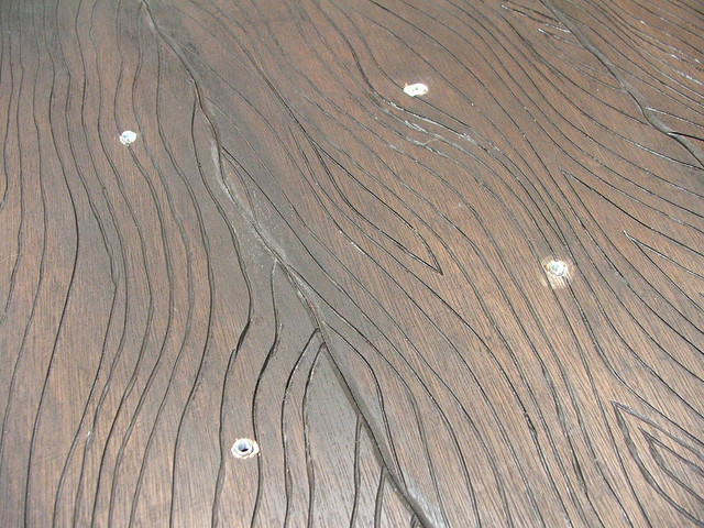
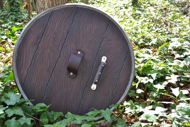
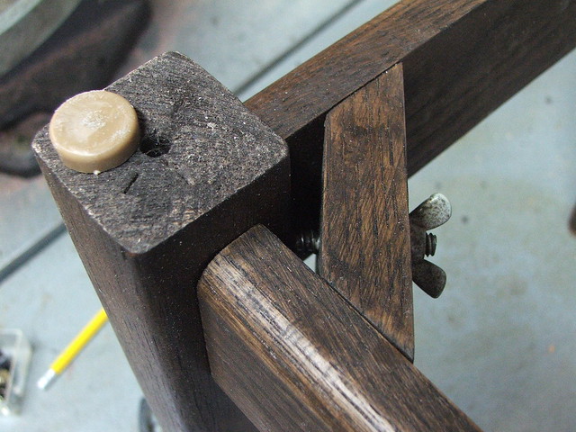
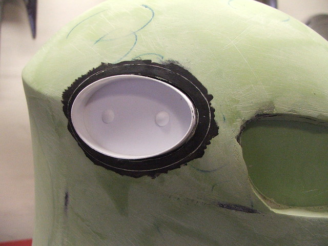
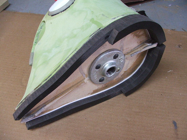
Four T-nuts were embedded into the back of the shield to hold the arm strap and handle in place. These only anchor into the wooden boards, and in retrospect it may have been a bit more structurally sound to adhere these two boards to one another as well. No failures yet, but I tend to over-enginner things for peace of mind.
The inner lip on the the shield was made with Apoxie Sculpt. As an added feature I hadn’t counted on, this actually made the shield far stronger. than just the boards glued to a foam disc.
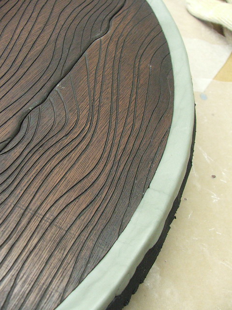
The remainder of the lip was built with bondo. Mostly this was a cost cutting measure since skinning the the entire outer edge in Apoxie Sculpt would cost an arm and a leg. I left some of the pits and gouges in the bondo when it was sanded to give the perimeter of the shield a bit more of a rougher edges like quickly banded metal. These are supposed to be utilitarian pieces made en masse for city guards, not museum pieces.

After taping off the wooden parts, the shield rim got a cot of primer and a few passes of hammered silver.

Onto painting! All of the work on the front of the shield was done with acrylics. The first pass was way, way too bright but I managed to pull it back down a bit more neutral later with some weathering and light yellow washes.
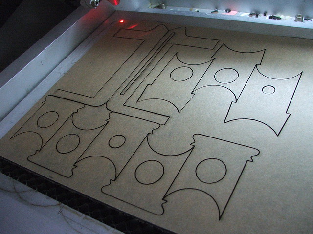
I will freely admit to being a bit spoiled by my laser cutting machine, and this was no exception. Painting the horse freehand would have been a disaster for me, so I made a set of paint masks, laser cut onto some stencil paper. Each quarter was laid down separately, then sponged over lightly to give me an outline of where to paint later.
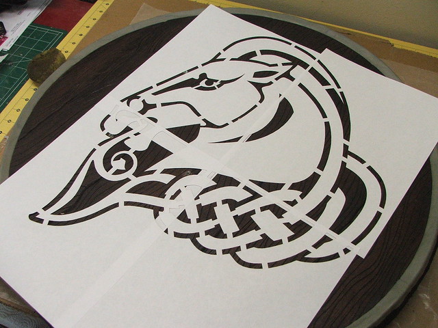

Here’s the finished sponged pass. I didn’t want to go too heavy here and risk later layers of paint looking uneven.
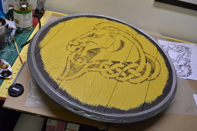
After a lot of filling in and close attention to staying inside the lines (thanks, kindergarden art class!) I had a finished horsey. I don’t think the Whiterun guards call him that, but I was kind of tired and loopy at this point so his name became “Horsey”.
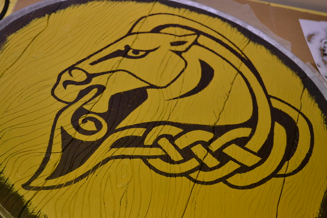
The shield still needed some weathering since the paint and horse were too vibrant, so I did a few layers of a more bleached out yellow, applied in streaks to give the paint a more uneven and randomly worn effect. This photo is an iPhone shot and it blows the colors out a bit, but the contrast helps call out the lighter areas somewhat better.
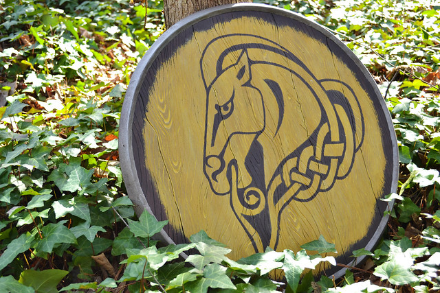
The finished shield! It only weighs about 2.5lbs, not bad for something this large.

Admittedly, the strap and handle aren’t the most impressive things in the world. My leather skills have a long way to go.
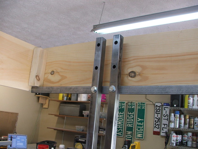
After the convention was finished, I needed somewhere to put this thing. Unfortunately, there isn’t much space on my walls for a 2-foot-large disc… but there’s plenty of room on the floor! I keep all my replicas in my game room, so I decided to make a little end table out of this guy.
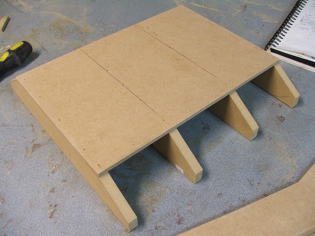
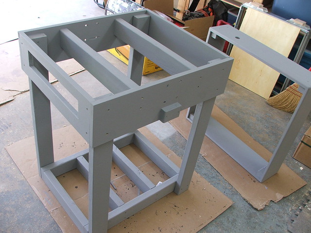
I already had an end table in my gaming room, but it was a thrift store find leftover from my college days – water ring stains on unfinished wood and a wobbly frame. Still, it had parts I could pirate for this project. I yanked off the legs and stripped the old finish with my orbital sander.
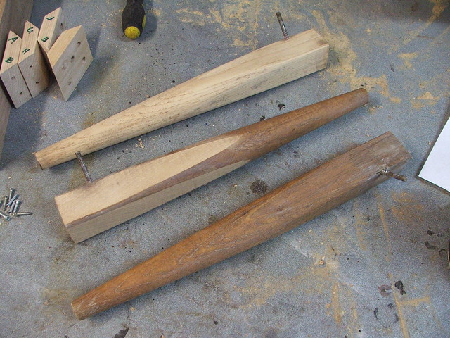
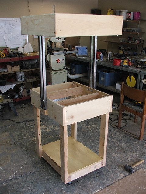
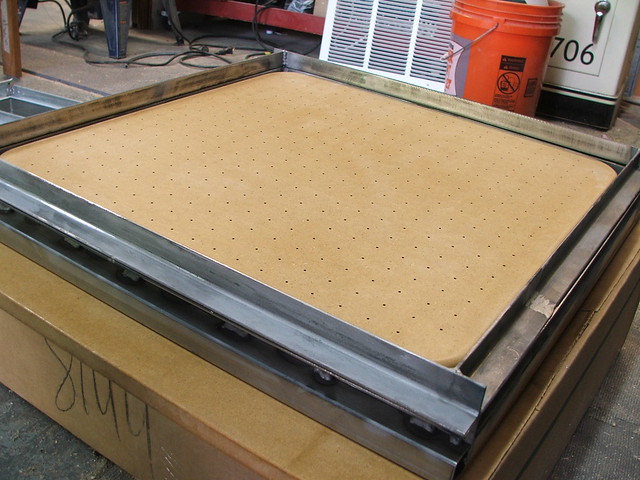
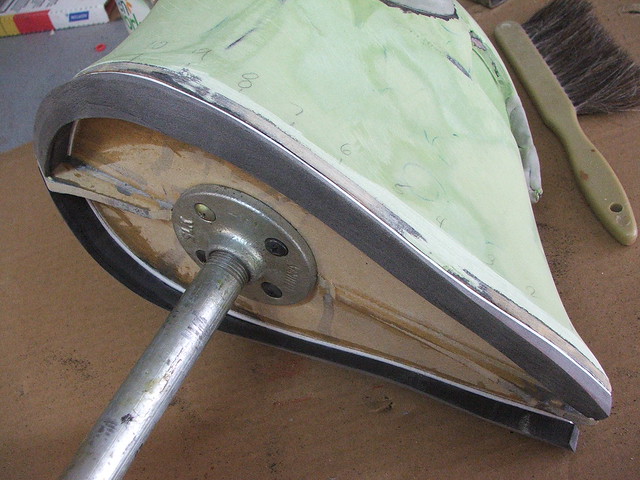
The legs turned out to be red oak, so I picked up a couple matching boards at Home Depot and built a simple box frame. The center running board holds the shield in place, anchoring to the two T-nuts used to secure the arm strap.

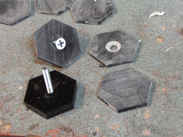
Each corner has a small nylon furniture foot on it that keeps the frame from scuffing up the under/backside of the shield.
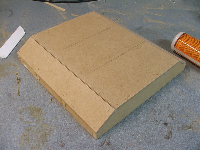
After sourcing a 24″ sheet of glass for the top (thanks, Mom!) I now had a much more impressive side table for my game room than my leftover college thrift store find.

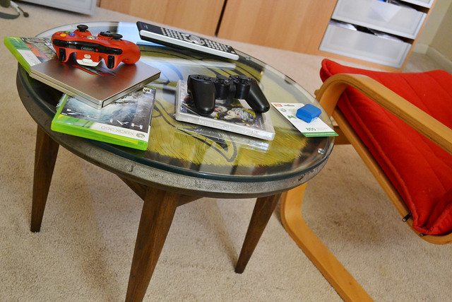
Obviously, it’s not always this clean. Here it is in a more natural scenario…

Thanks for reading!

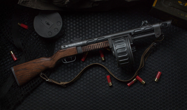
Combat Shotgun, Fallout
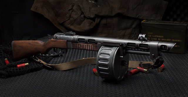
I was commissioned recently to make a replica of the Terrible Shotgun (aesthetically identical to the Combat Shotgun) from Fallout 3 and New Vegas. If you’ve seen my previous AER-9 builds you know I’m a pretty big fan of the Fallout universe, and the Terrible Shotgun was a piece I’d wanted a chance to build for quite a while.
A special thanks goes out to Mike McDermott (BillyBob884 on DeviantArt) for his pepakura skills: he put together a pep file of the Combat Shotgun available in very handy PDF format, that I referenced more than a few times during the course of this project. Thanks dude!
I should mention, this is a MASSIVE write up. Grab a cup of coffee, you’re gonna be here a while.
This project is, I suppose, a bit more technical than some of the others I’ve done in the past. I think one of the nice parts about my write ups is that things are largely pretty approachable. Recently I’ve made a really large vacuum forming machine, gained access to a laser cutter, and for this specific project I channeled my old Furniture Design degree and picked up a miniature milling machine to work with aluminum. While many of my previous projects require something akin to a bandsaw as the most complex tool, this shotgun is definitely not a “beginner” project.
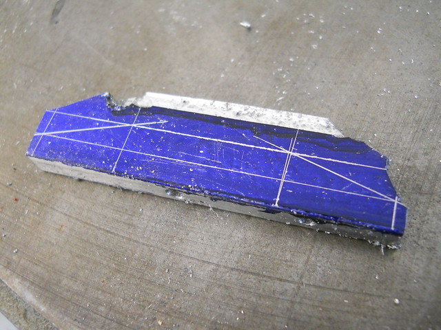
Even still, the roots are similar. I started off by making blueprints in Illustrator, based on as much in-game reference as I could pull together.

The combat Shotgun is based quite heavily on a Russian machine gun put into service during WWII, the PPSH-41. Barrel heat sink, sights, drum magazine – many parallels can be drawn between the two designs. I started off with a PPSH diagram lifted from a vintage WWII manual which gave accurate millimeter dimensions of all the associated parts. I scaled the stock on the Combat shotgun to that of the PPSH rifle, and the remainder of the blueprint was scaled accordingly.
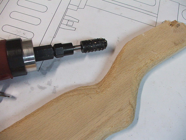
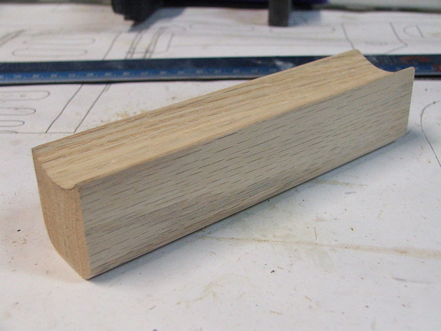
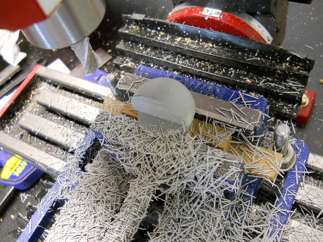
I chose to make the stock on the gun from laminated sections of red oak. The areas for the trigger mechanism and barrel mount were cut from the center section before gluing the sheets together, as this made these recessed cavities much easier to construct as opposed to chiseling them from a solid chunk of wood.
Red oak is about as easy to sand as a block of concrete, so more drastic methods were used to get the stock into shape. I started out with a rather angry looking grinding drum and gradually worked my way through 50 grit sanding paper all the way up to 400. I attempted to chisel out some sections, but the oak splinters very badly and I found grinding to be the best method of getting the proper look and feel.

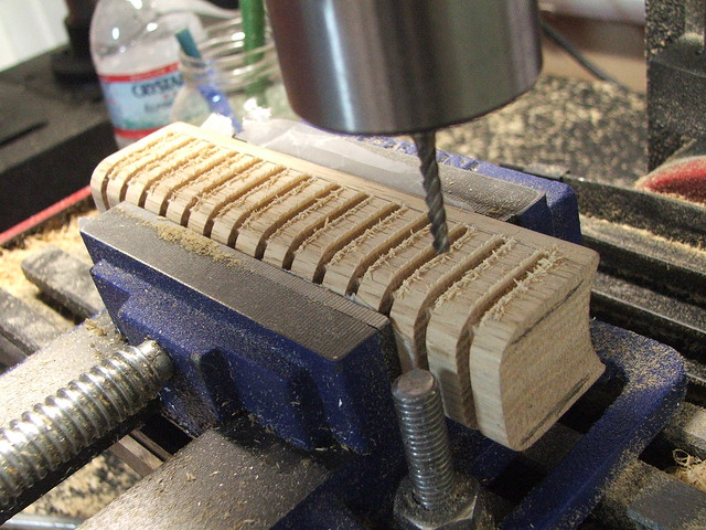
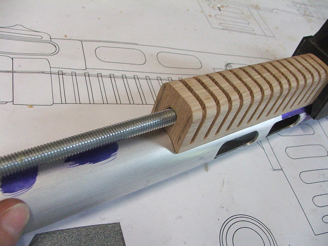
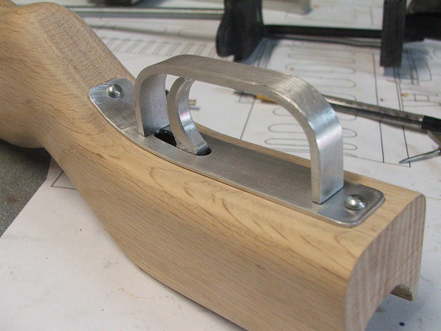
The forward grip was also shaped from a block of red oak. The grip channels were added on my mill with a (very long) bit. It’s what I had! The lower grip sits on a long threaded rod which passes into the rear stock and the magazine catch.
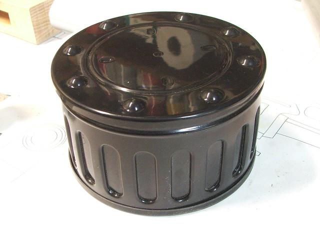
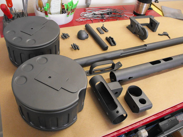
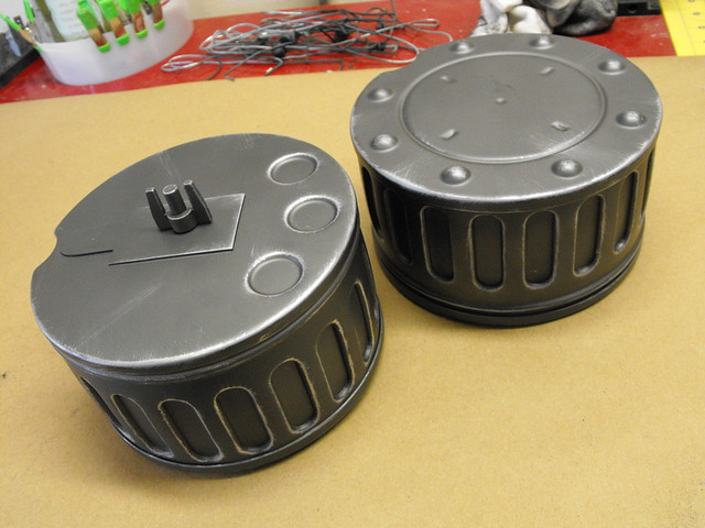
At this point I switched over to the drum magazines. These parts are assembled from three pieces which are all vacuum formed from ABS plastic. The bucks were made from MDF with acrylic parts and furniture tacks used for added raised details.
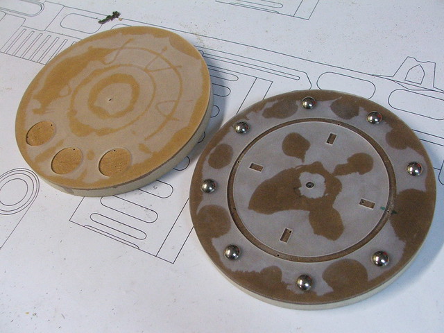
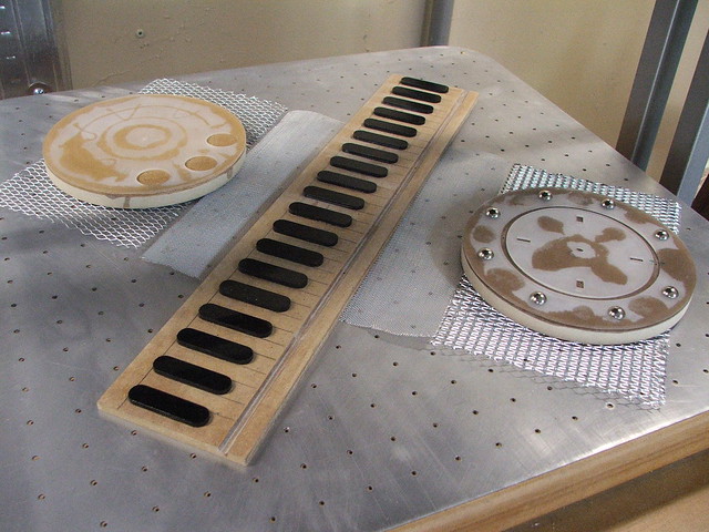
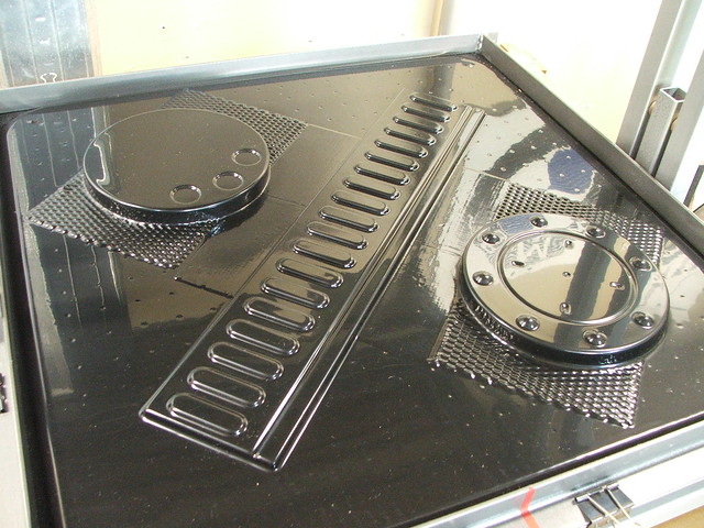
After the ABS was pulled over the bucks and trimmed out, the center section was inserted into a PVC coupler and gently heated until it retained the proper curve to match up to the front and back plates.
This is one of the magazines loosely assembled to check for fit.
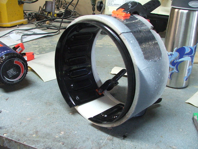
These still needed a fair bit of additions to be functional. The finished gun was supposed to be able to exchange magazines easily, and I’d decided on a magnetic catch to hold them in place. Also, while the ABS held its shape fairly well, the large flat sections flexed very easily. The shot below shows the interior bracing of one of the ammo drums. The clear acrylic makes sure the outer panels don’t flex inward, while the white styrene ring keeps the side panel in place during gluing, ensuring a proper tight fit.

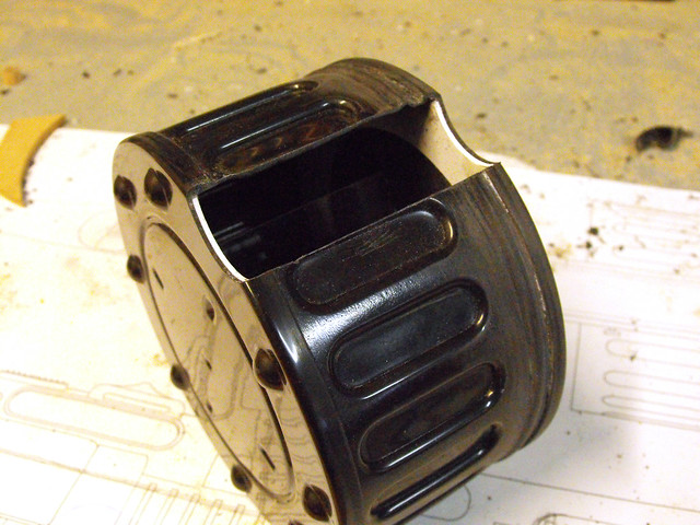
The upper sections of the magazines were cut out in a semicircle, and an ABS pipe was glued in place (sanded down from the last shot below, that was just rough placement.) The inner diameter of this pipe matches the outer diameter of the heat shield on the gun, where matching magnets were mounted. A large ceramic magnet was epoxied to the inside of this piece before gluing the magazine shut.

The last pieces for the drum magazine were the alignment panel and wing nut. The white piece on the front here mates up with a channel in the magazine holder on the gun, which makes sure the magazine doesn’t shift around. The wing nut is a piece I molded in order to make multiple copies for multiple magazines.

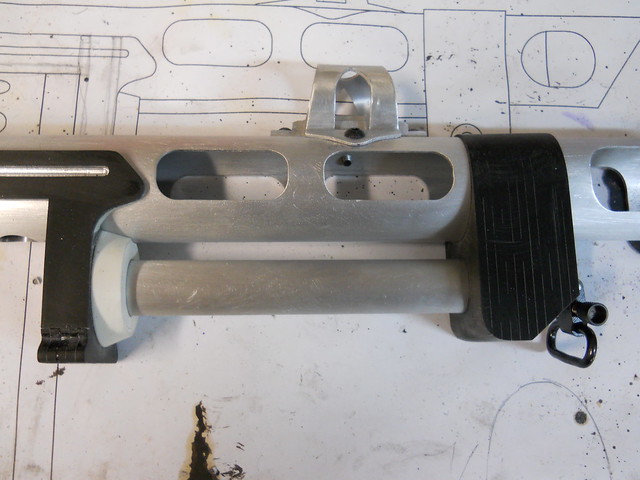
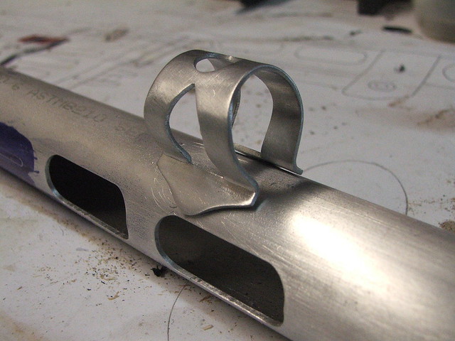
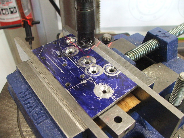
Getting back to the meat of the build, I had sourced a few different diameters and thicknesses of aluminum pipe for the barrel and heat shield. Over the course of the project, I milled/drilled/tapped dozens of holes in these pieces for various elements.

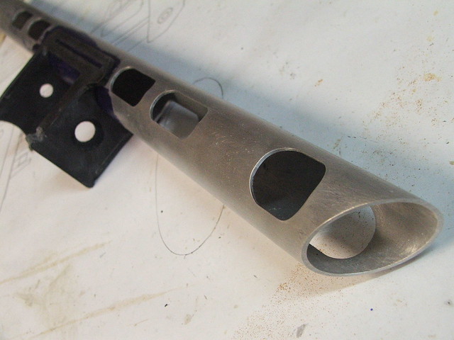
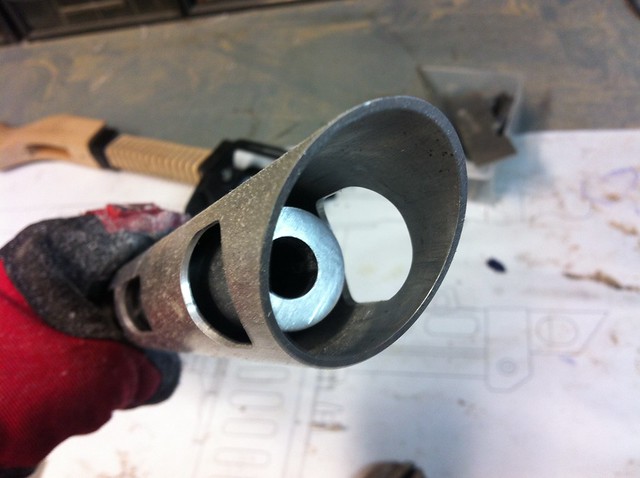
This area of the gun is the inside of the magazine holder, and the four large holes mark where 4 neodymium magnets are mounted to hold the magazine in place. The slot cut out of the inner barrel makes sure this clears the magnets when all the parts are installed. The magnets themselves aren’t actually glued into anything; they sit inside the drilled holes and pull towards a steel plate held in place on the inside of the heat shield. The pull on these is much stronger than the pull against the actual drum magazine, so they’re not going anywhere.


The magazine holder itself was made out of several pieces of laser cut acrylic, laminated together. Might be hard to follow the progression from the first shot to the second here, but these are just a bunch of flat parts glued into a big brick!

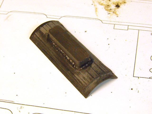
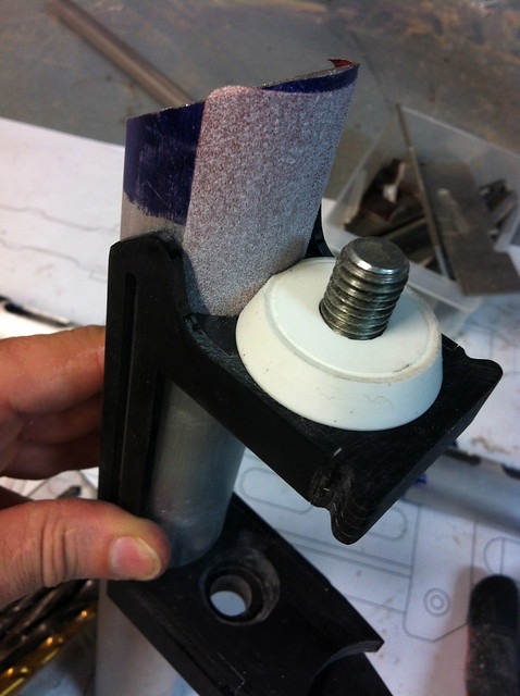
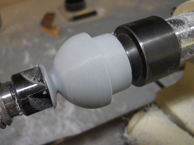
A few additional elements were made out of lathed urethane resin for the mag holder. These make up the small round drums in the front and back. The front piece had to be sanded to shape to mate up with the heat shield, so I spray mounted some 120 grit paper to a section of scrap pipe and gradually removed material until I had the desired shape.
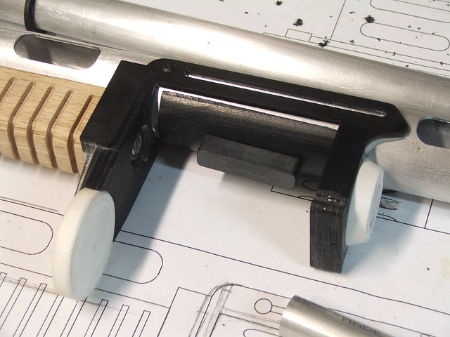
This U-shaped channel in the front mates up to the panel on the front of the magazines mentioned earlier. The rounded edge makes it easier to get the magazine into the slot even if your approach is a bit off.
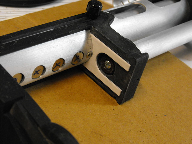
There’s a large block on the front, which probably has a name I can’t identify, which was made with a similar “layered” process. The base parts were all trimmed in 1/8″ acrylic, and the various sized holes correspond to screws and pipe that need to fit into the front and rear sections of the part.
This pic explains that last sentence a bit better. The rear of this block holds the grip piston in place, while the sling swivel is mounted to the front.
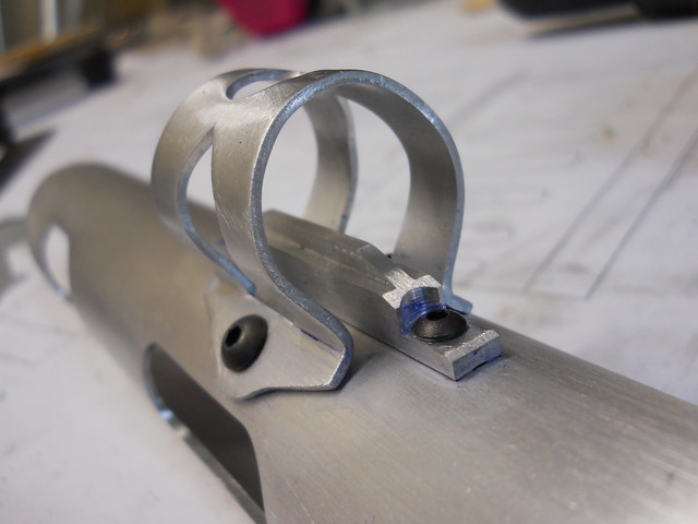
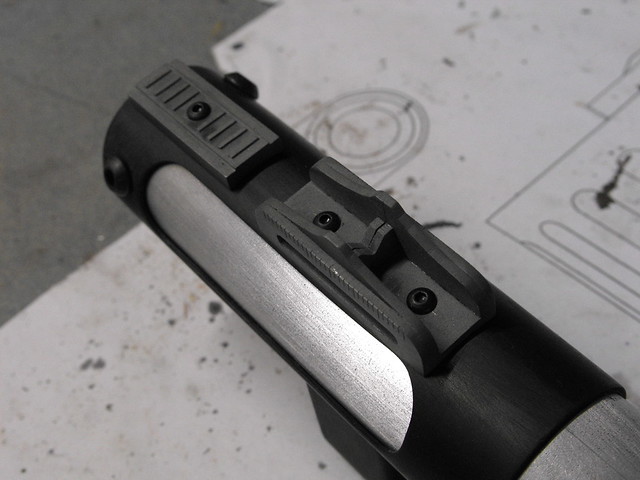
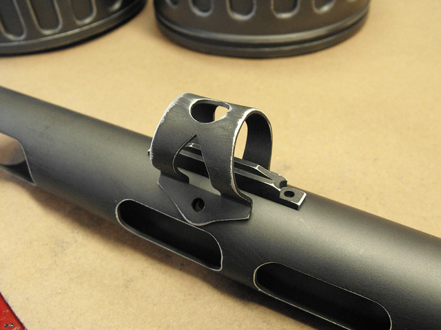
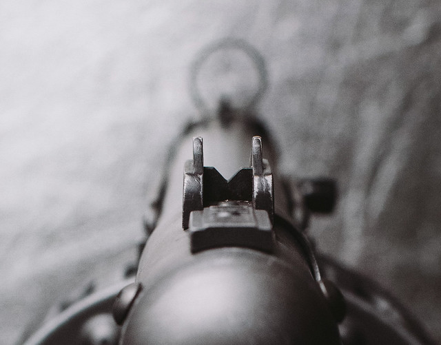
In the shot above you can see the finished forward sight and ghost ring. These both started life as boring chunks of aluminum. The ghost ring was gradually hammered over a round buck (for much longer than I’d expected) to get the proper shape. Holes were drilled in the mounting tabs that lined up to tapped holes on the heat shield.
The actual forward sight was a block of 1/4″ thick aluminum milled down into something a little narrower and more detailed. I am very lucky to have inherited some of my grandfather’s milling bits which have enabled me to do small detail work like this without having to sell a kidney in order to afford the necessary mill accessories.
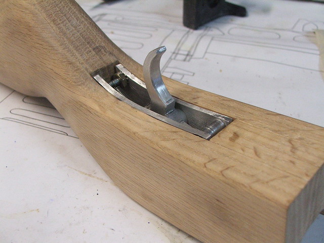
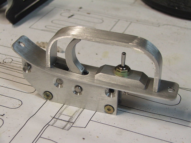
Speaking of aluminum work, there was plenty to do on the trigger mechanism. Side plates were cut from 1/8″ thick stock, while the trigger itself was milled out of 1/4″ material. Threaded spacers and a return spring completed the main mechanical assembly.
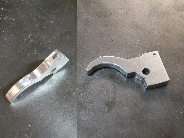

This drops pretty neatly into the cavity in the stock, and I cut a thin aluminum plate to cover up the mechanism.
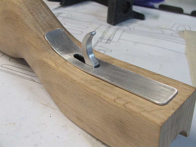
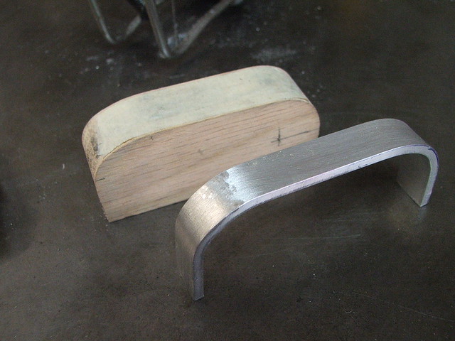
A trigger guard was hammered over a wooden buck, then threaded for some very small machine screws and mounted to the plate.

The last part of the trigger assembly is the safe/semi/auto switch in front of the actual trigger. On a real PPSH this is a slide switch, but in the Fallout game files it’s a toggle. Weird, since the gun has no full auto feature, but I just makes it like I sees it.
Moving forward and a little bit up to the barrel heat shield again, I needed to make all the bits that sit at the back near the shell eject port. The shroud around the barrel was made from ABS pipe and laminated acrylic; I cut the port on the side with the mill.

The rear sight and safety switch (I guess that’s what the block behind the sight is supposed to be?) were made from acrylic parts, then molded and cast with aluminum powder in urethane resin. The stock butt plate was molded along with these parts, after being sculpted from a block of urethane tooling board.


The rear shroud slips over the barrel heat shield, and is held in place by the screws securing the iron sight and rear safety switch.
One last part was made from resin for the rear of the rifle – the barrel end cap. This was initially lathed, then put in the mill to have one side leveled off in order to lay flat over the rear stock.
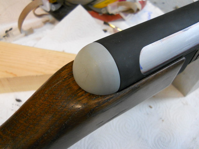
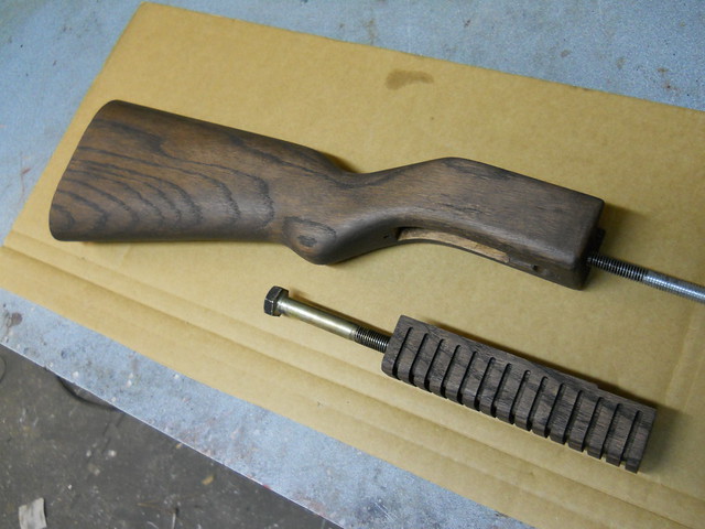
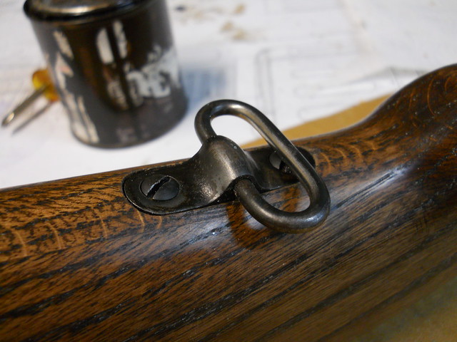
You might have noticed the glossy and pretty stock in the shot above. Both the stock and the grip received several coats of wood stain, buffed with steel wool between each coat. After allowing several days to dry, these parts were buffed with paste wax. Shiny! I also added a rear sling swivel (off a 1914 Enfield) to the rear stock.

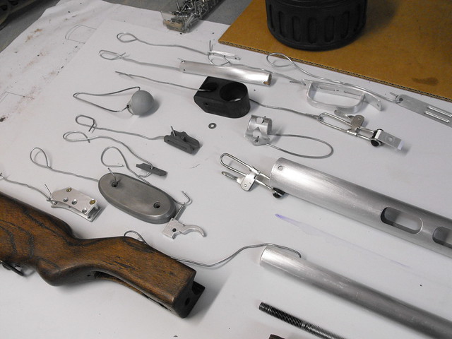
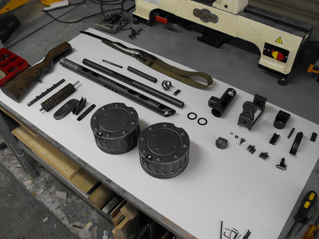
At this point, all the major components were finished! The gun is built in such a way that it can be taken apart down to its individual components if any maintenance needs to be done (it was originally intended for a film shoot.) All parts are screwed together and there are no glue joints. Below are all the parts laid out before assembly (screws not shown) then after assembly. I did many test fits to make sure everything worked together, and there is a very specific order you have to go through to put it all into one gun.

All of the painted parts were put on hangers and then painted with black primer, followed by Testor’s “buffable metalizer” paint in gunmetal gray. The color on this paint is beautiful, and it can be buffed with a soft cloth to a nice metallic sheen.

Weathering was done in a fairly subtle way. The aluminum pieces were scuffed along the edges with a 220 grit sanding sponge to bring out the natural metal color underneath. Plastic and resin parts were dry brushed with enamel paint to match this effect.
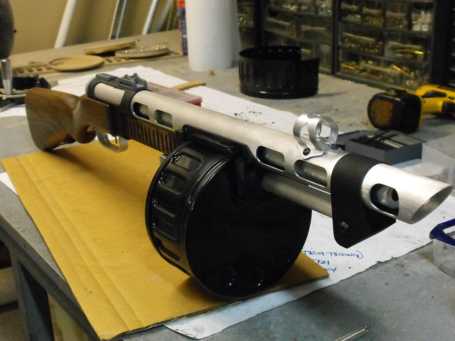
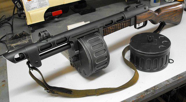
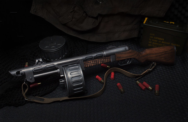
After all the parts were dry brushed then clear coated and given 24 hours to dry, the gun was laid out for assembly! I’m no pro when it comes to field stripping and rebuild, so the process of making this into one finished prop took me a little under 2 hours. The finishing touch on the gun was a vintage PPSH-41 strap, shipped direct from Russia!
It’s a blast to hold and you feel like a total bad ass walking around with it. I wouldn’t really suggest that last part outside of your living room though, because you could easily mistake this cannon for the real thing and get in a lot of trouble!
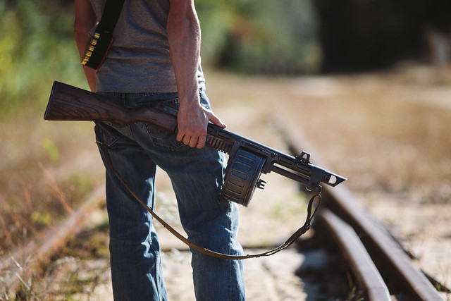
Pics of the final shotgun, taken by my good friend Dan Almasy. Extra props in the set up really complete the look!


The butt plate on the gun is engraved with the Dracogen logo, the official sponsor of MANY things “geek” culture and the commissioner of this fine piece here.

Total time from start to finish on this project was 4 weeks. Not bad for such a complex project!
If you’d like more pics about the gun’s build (believe it or not, I left a LOT out of this build description!) then please take a look at my Flickr. Larger resolution images of the finished piece can be found in my portfolio gallery.
Thanks for reading!

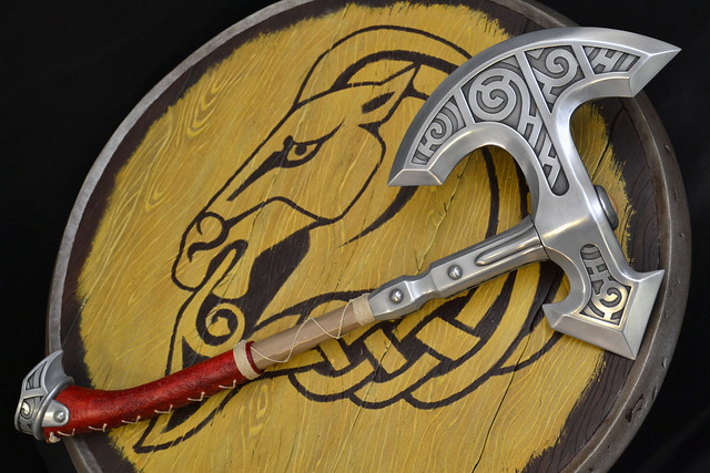
Steel Axe, Skyrim
Continuing with the Skyrim trend, but not a helmet this time!
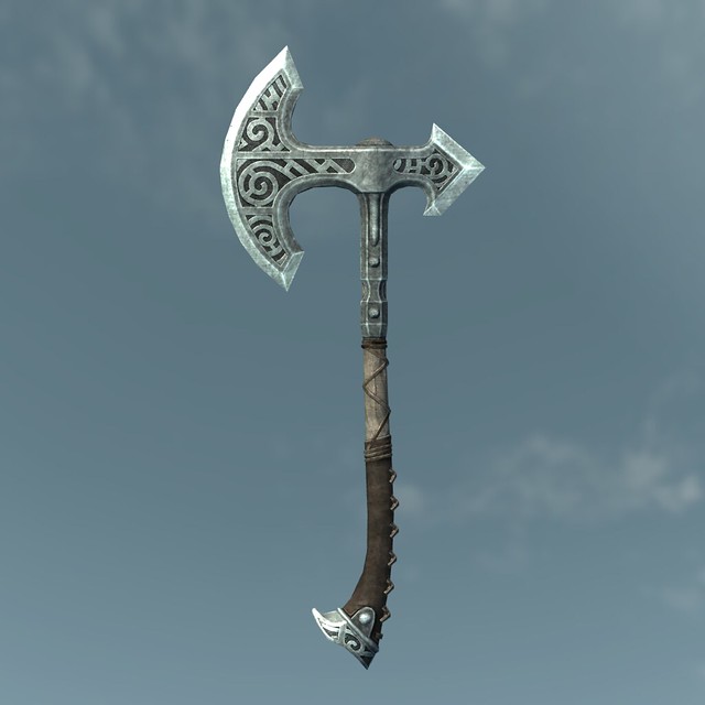
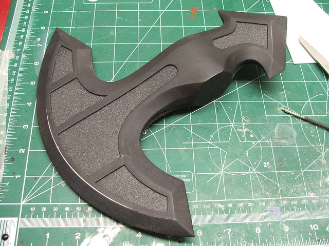
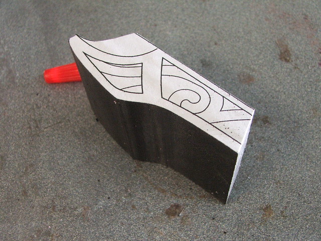
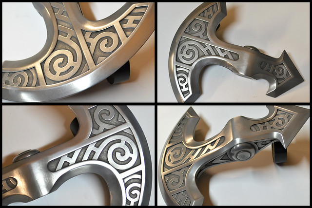
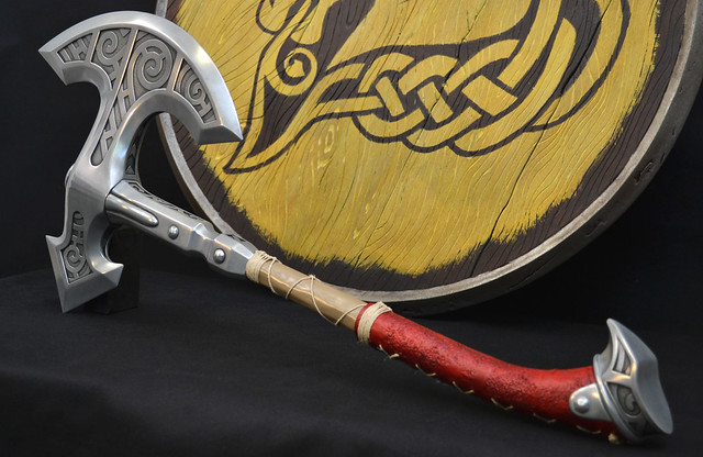
There are all sorts of intricate and complicated weapons in Skyrim, but the Steel weapons – low level though they may be – possessed a very cool concentric circle pattern to them that I thought looked particularly awesome. When a client asked me if I had any interest in making the one-handed axe, I jumped on the project.
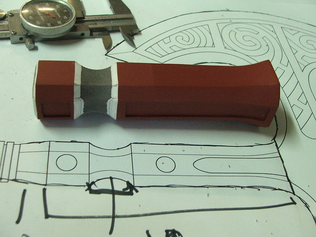
The base shape of the axe was laid out in illustrator, and I used these blueprints extensively in making the mold master.

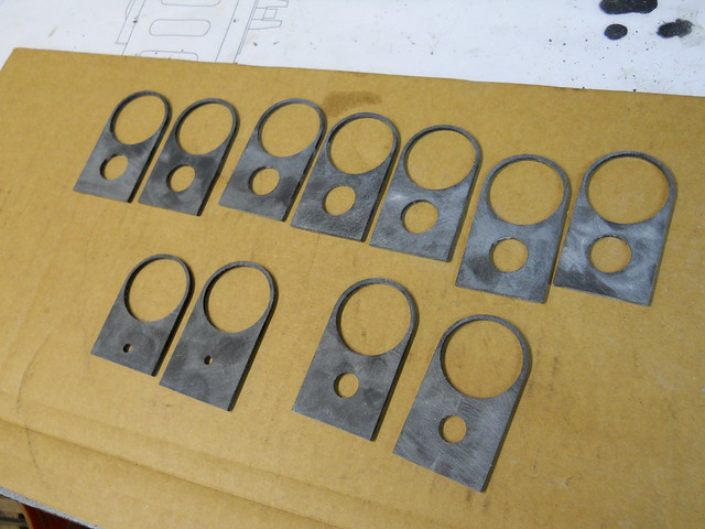
The axe head was where I started my efforts, and this began with several layered pieces of laser cut acrylic. Having the blueprints in vector format made transitioning to laser cut pieces very easy.
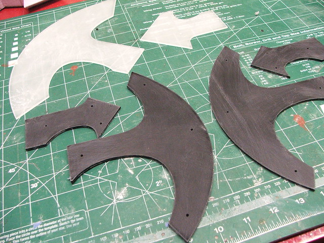
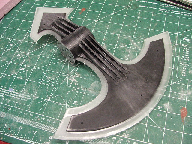
Angled risers in the center make up an internal frame structure that makes sure the layer on top has the proper curve to it. The facing edge was added in thin styrene sheet in order to make the curve from the center of the axe head out to the blade.

The whole project was really an exercise in layering. More styrene was cut on the laser to make up the outer perimeter edges of the axe, which surround the concentric circle patterns. Panels like this were added to the top and bottom as well as the sides of the axe.

Things don’t come out of the laser cutter perfect though. There was a lot of sanding and cleanup in order to get the edges crisp and round.

With the base form done, the blade sections of the head were filled in with apoxie sculpt, then sanded down to a pointed edge. There was a also a bit of cleanup needed in the center area of the axe head where the styrene edges curved into the middle.
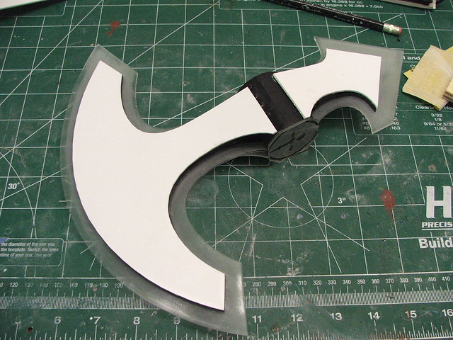
Behind the raised filigree patterns is a stippled texture. This was simulated with Rustoleum multicolored textured spraypaint. I’ve used this in the past to make a grip texture on pistols and rifles, and the effect it gave me here was pretty spot on to what I saw in the game renderings. The outer edges were masked off first before spraying.
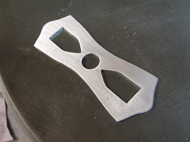
The filigree parts were laser cut (man I love that thing!) from .020″ styrene. The outer edges trimmed out before were .060″, so this very thin stock provided a small raised section while still sitting lower than the surrounding parts.


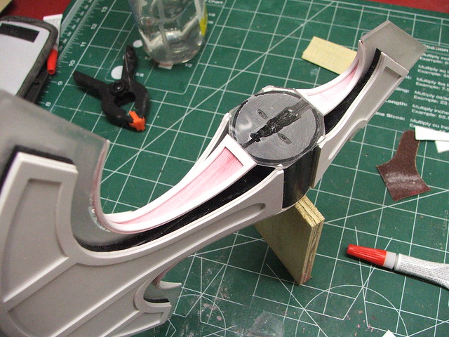
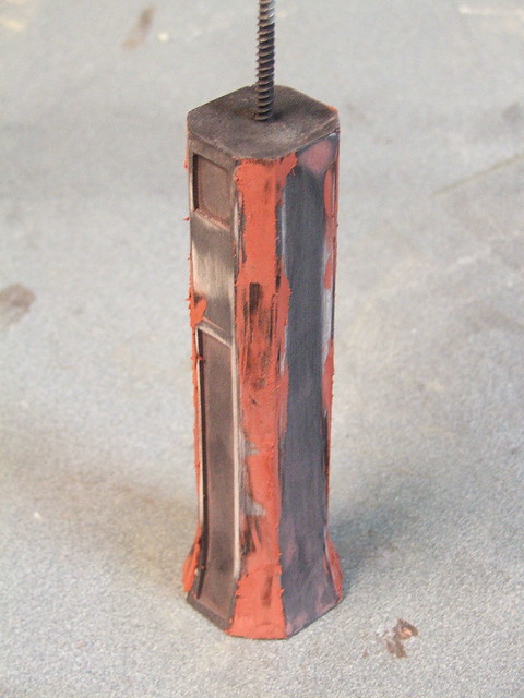
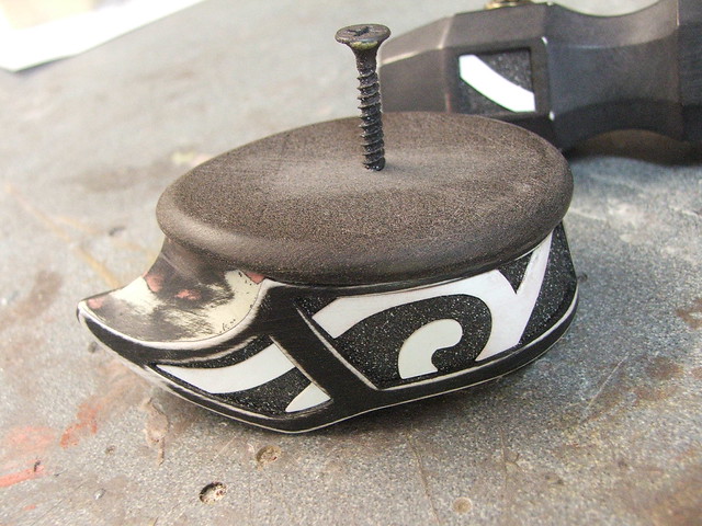
The last piece needed for the axe head was the top nut, which was lathed from a resin block and glued to the top of the axe head master.
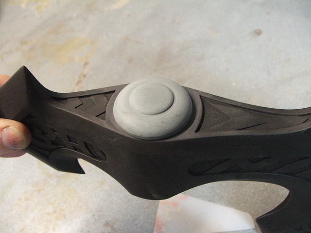
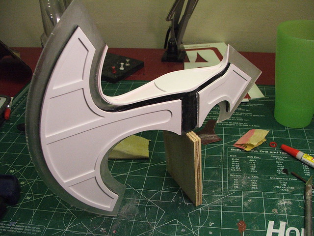
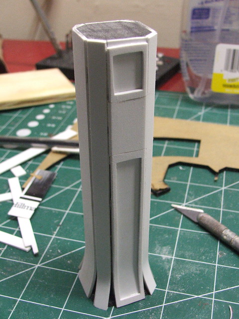
Next up was the neck and pommel. These followed a similar technique to the axe head. I started off both with blocks of sintra, then layered on styrene to build up the perimeter shapes. The neck part was more geometric, while the pommel was a bit more of an exercise in free-form dremel and belt sander sculpting.
The neck section at the beginning. The little tabs at the base serve the same purpose as the ones in the axe head, giving shape to the styrene layer which will go on top.
This technique needed a lot of putty on the seams to make everything flush and pretty, but the end result was great.
A bit of apoxie sculpt on the sides, then some furniture tacks for rivets and filigree parts cut from .020″ styrene.
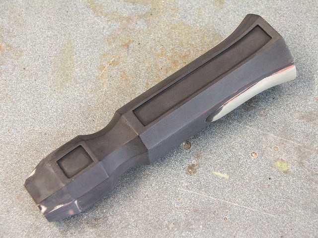
The pommel had essentially the same build process, but with a little bit of bondo filler tossed in to make everything smooth and even on the curved panels.

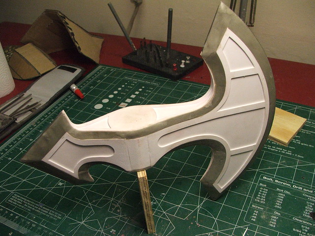
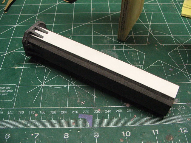
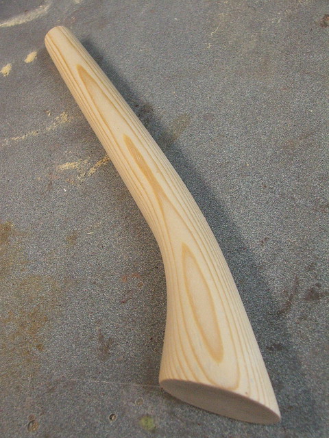
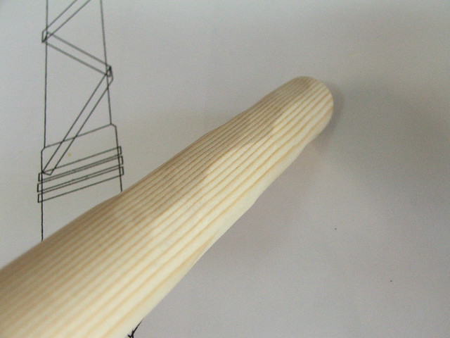
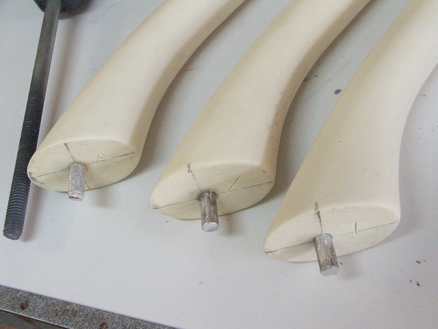
Handle was up next. It’s wood, right? Let’s make it out of wood.
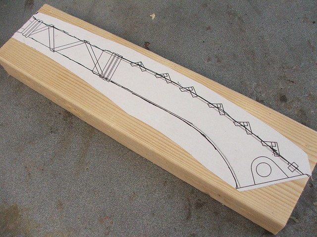
What started life as a simple humble 2×4 wall stud has a much more glamorous existence now. Sometimes I feel bad for all the sheets of MDF at Home Depot that have to live as shelves instead of space guns and cool weapons. Anyhow, I added some chunky cuts into the upper area of the handle to better match the game art.
Last part! These little guys are the rivets that would hold the pommel onto the handle. They’ll be decorative on my axes, in order to make the handle wrap easier to do later on.

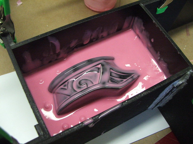
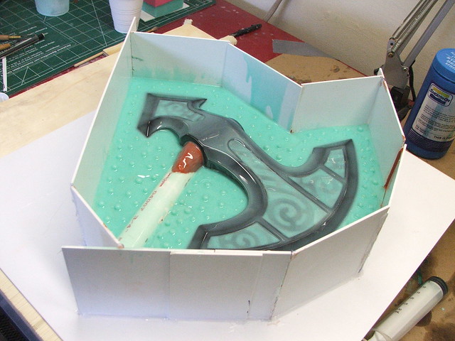
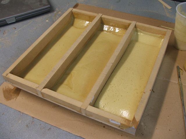
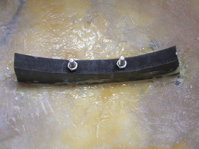
Now toss everything in clay and throw some rubber on it. The pink rubber here is Mold Max 30, the greenish stuff is Mold Max 40. 40-weight is my new preferred material for block molds like this.

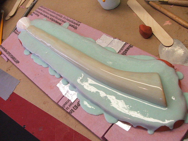

Wait 12 hours, then repeat.
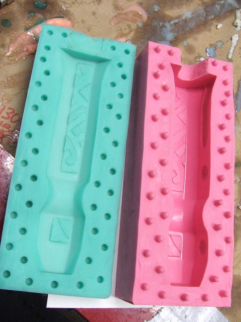
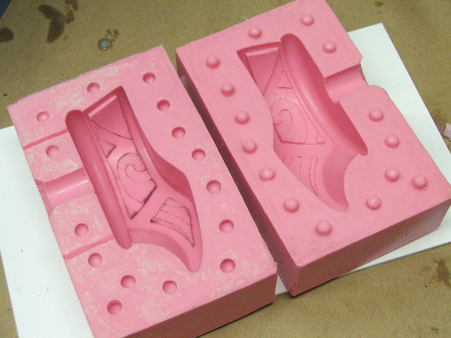
Molds finished!

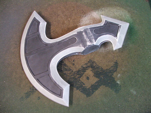
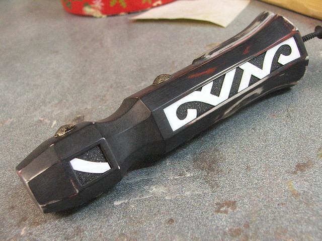
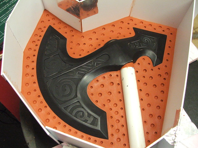
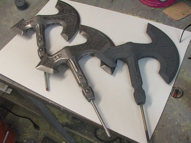
These parts were cast in Smooth Cast 320 urethane resin with black tint. There’s a process called “cold casting” which I’ve done on my helmets in the past, but only for a subtle metallic texture underneath paint and weathering. For these parts, I first powdered the molds with aluminum, then poured in resin with aluminum powder mixed into the plastic.
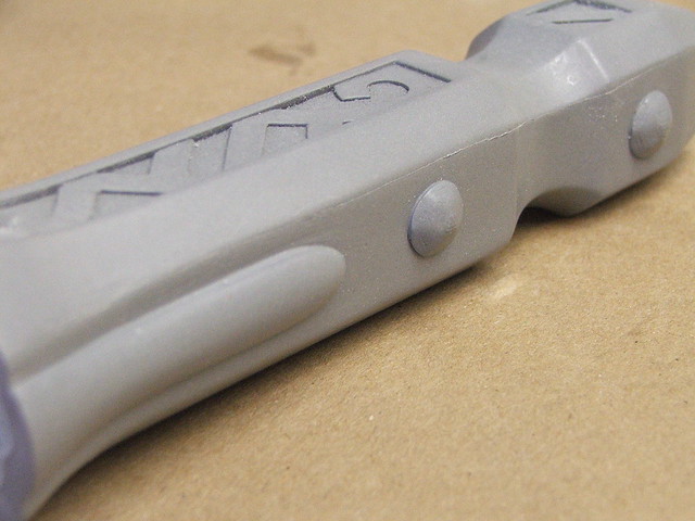


Once the part is cured, you can buff it with 000 steel wool, then polish it to a bright metallic shine. I used Mother’s aluminum mag wheel polish on my parts to get them this shiny.
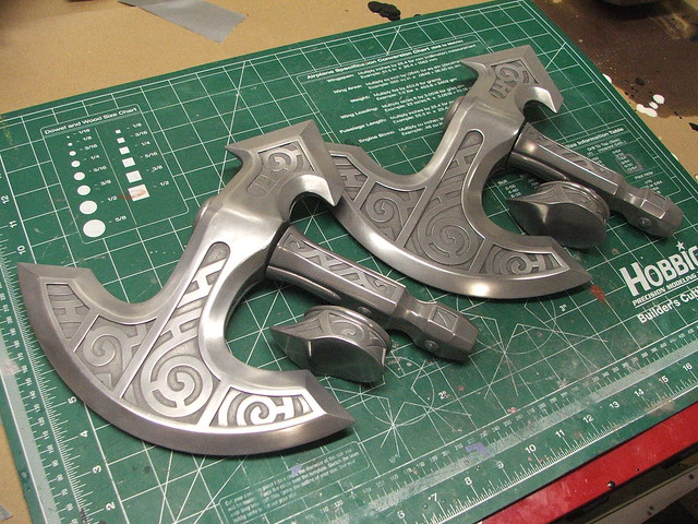
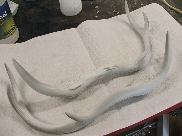
Plugs and rods were inserted into the neck, head and pommel then epoxied into place. A 3/8″ steel threaded rod runs the entire length of the handle on these pieces, making them extremely rigid.
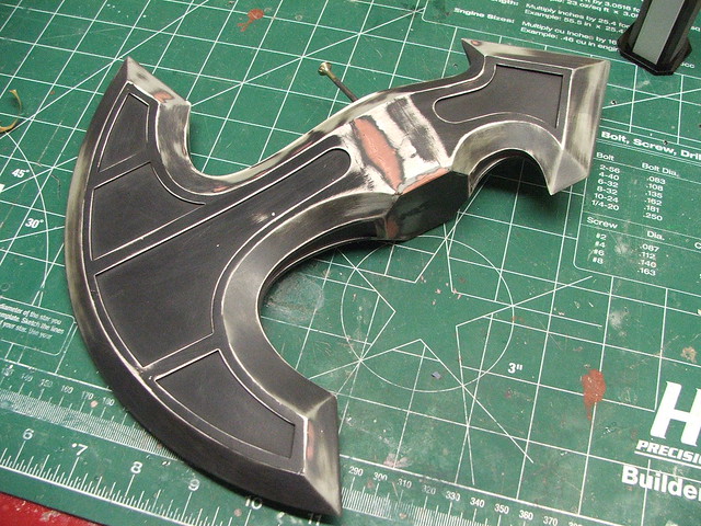
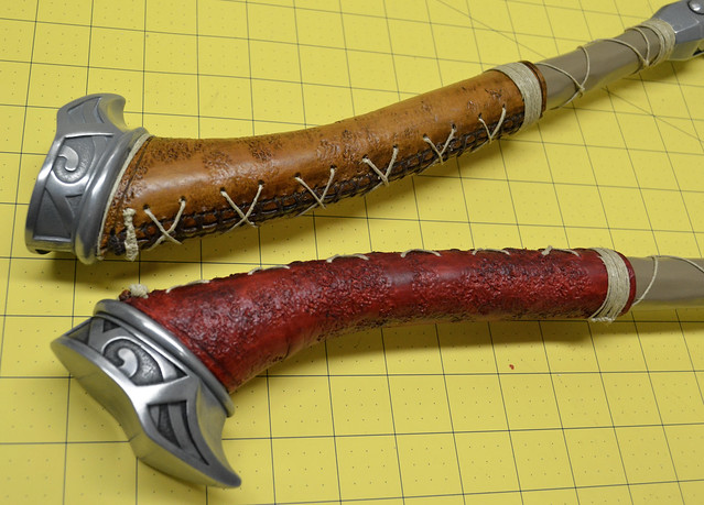
My friend Cathy over at God Save The Queen Fashions did the wraps on the handles for these pieces. The axe that was sent to my client has the correct tan color to it, but I have a thing for the color red, and asked that my handle wrap look a little different.
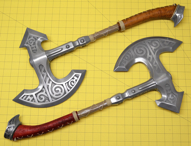
After a light pass of weathering to darken the recessed areas around the filigree, the project was finished! The final piece weighs about 2.5lbs and measures 26″ long. Interested in making one of your own? I sell raw cast parts in my store, check them out here!

The Shield of Whiterun is another project I wrapped up over the summer which still needs a writeup. It’ll be a short one, but expect that to come soon!


More pictures of the build process in higher resolution are available on my Flickr page and in my Portfolio if you’re interested in learning a bit more detail about the project.
Thanks for reading!


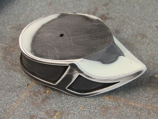
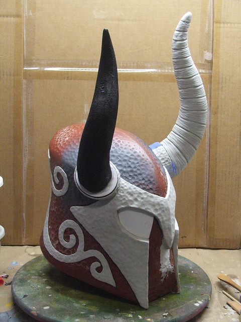
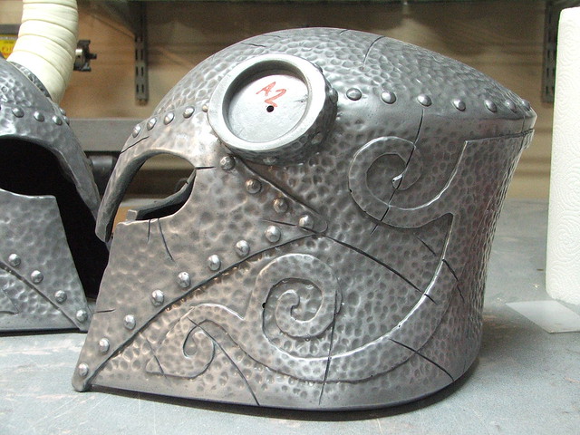
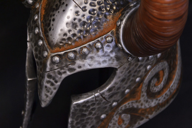
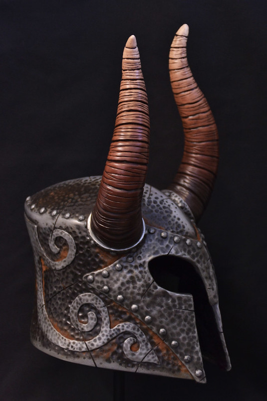
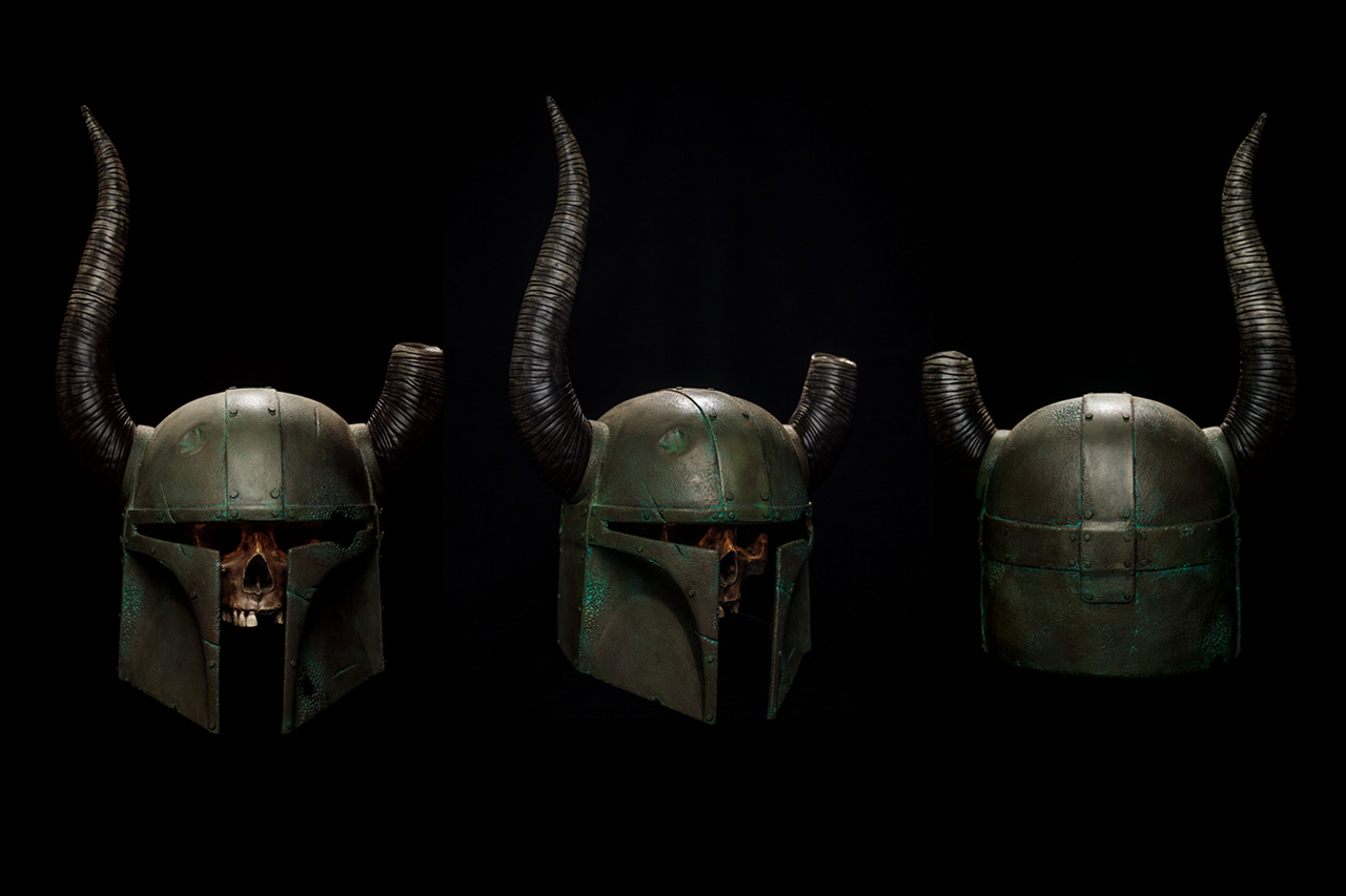
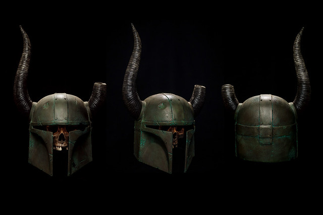
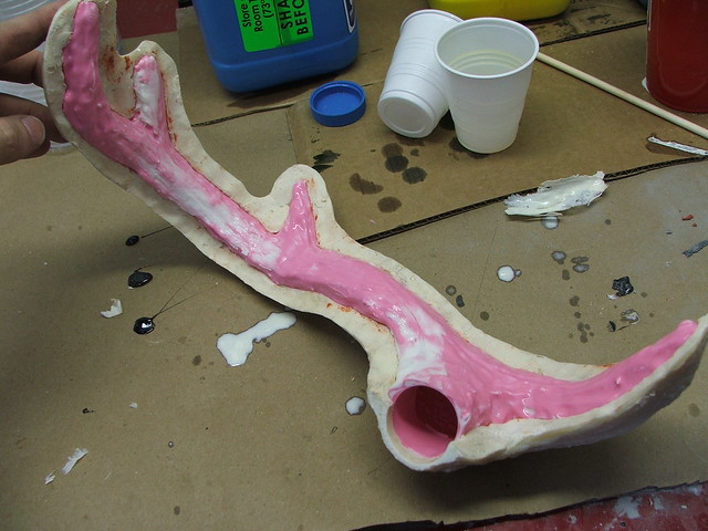
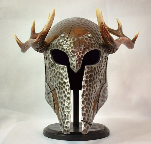
Helm of Yngol, Skyrim
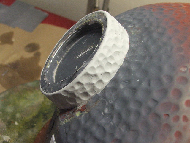
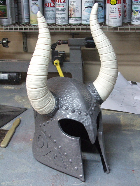
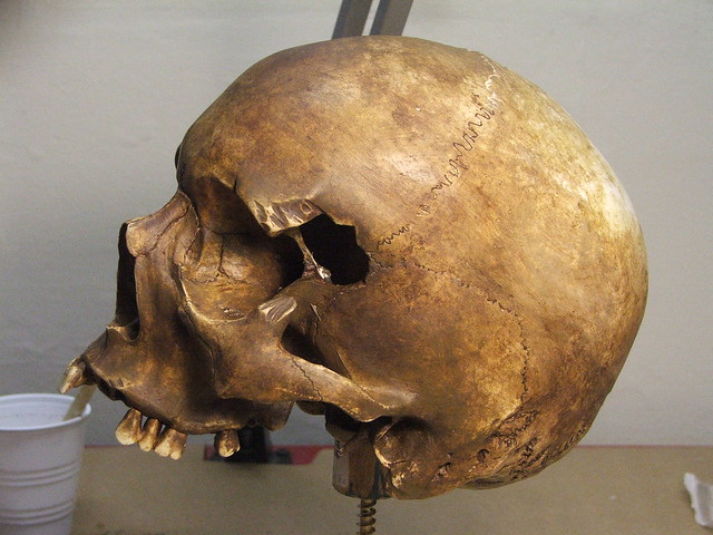
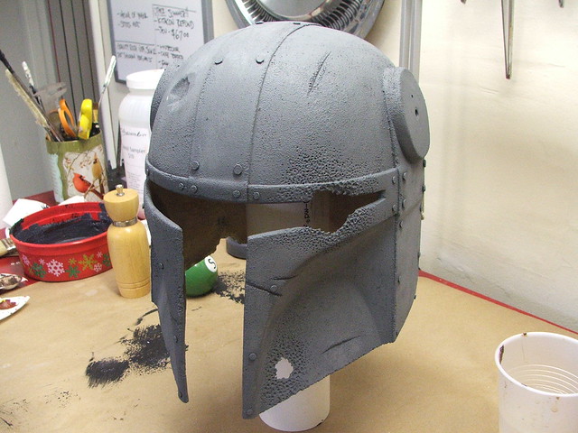
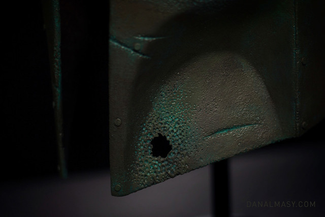
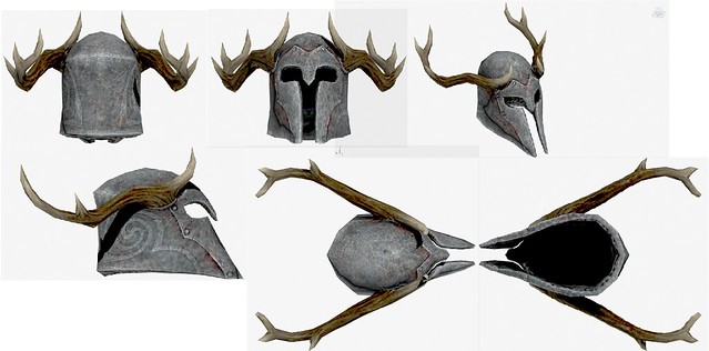
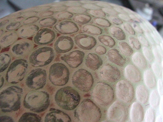
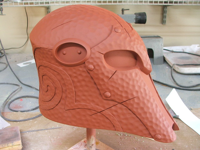
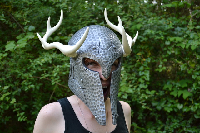
So I’ve been on a bit of a Skyrim kick recently. I’ve completed several projects from the world of Tamriel which will be popping up on this blog in the next few weeks, but the first one I’d like to feature from my latest build bonanza is the Helm of Yngol. The image below is actually far paler than how the helmet shows in the game; the horns are much darker and the helmet shading is nearly black.

Originally the client who commissioned this piece was interested in getting the more standard Iron Helmet, but stumbled on this piece in one of the many caves in Skyrim and immediately changed his order!

If you’re interested in a more immediate recap, I ran a GoPro camera in my shop while this project was being built. 280 gigs of video and a full day of editing later, you can watch the entire process in less than 4 minutes!
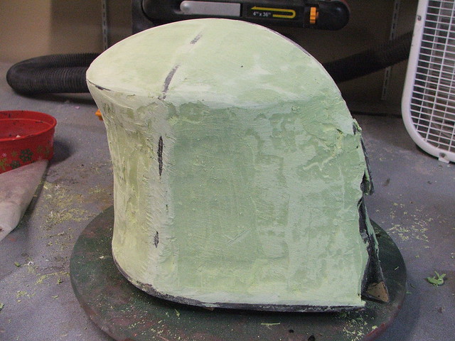
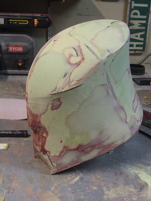
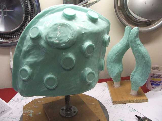
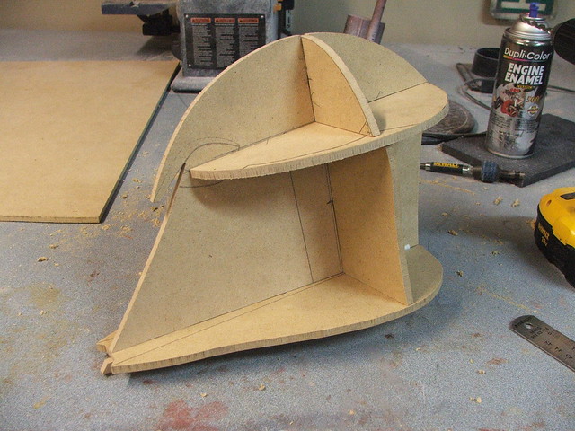
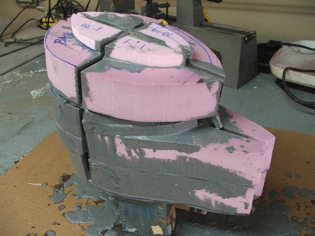
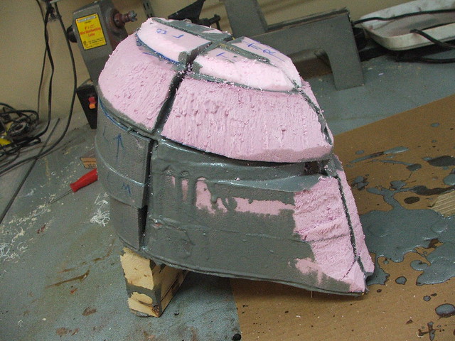
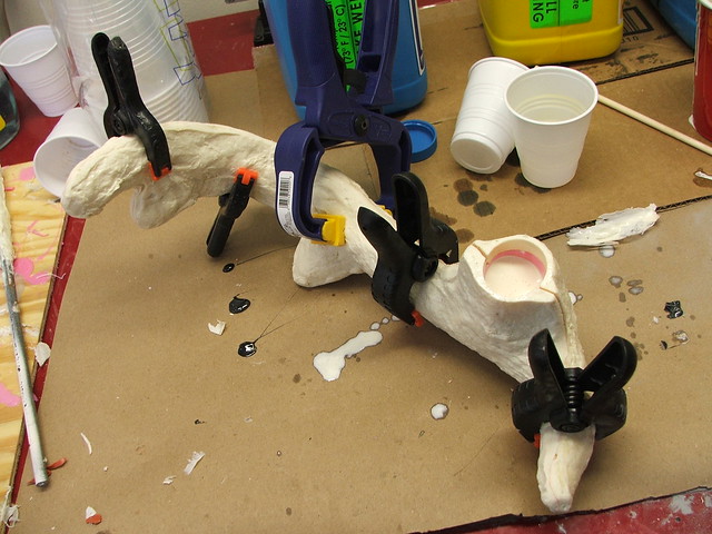
The process here is very similar to my other helmet builds, most notably the Female Draugr/Ancient Nord Helmet I completed earlier this year. A basic frame was constructed from 1/4″ MDF and filled with blocks of insulation foam, which were carved into a rough shape.


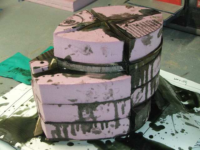
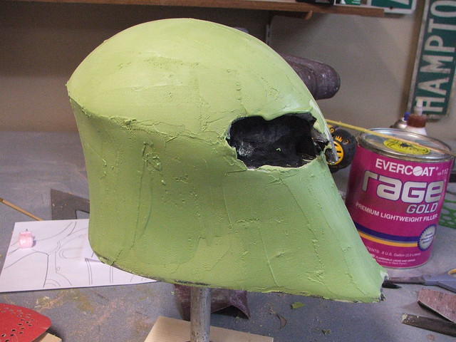
The basic form was then painted with acrylic paint. This is a barrier – the extruded polystyrene insulation foam is very solvent sensitive, and the bondo process in the next steps would dissolve it if not for this coating.
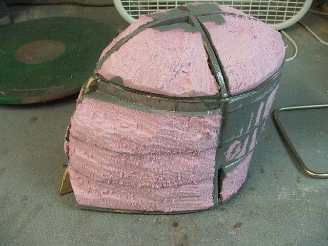
There were several coats of polyester filler used to build up the shape and make things symmetrical. The green stuff in these shots is “Rage Gold” by Evercoat. Sands very smoothly and spreads evenly too.
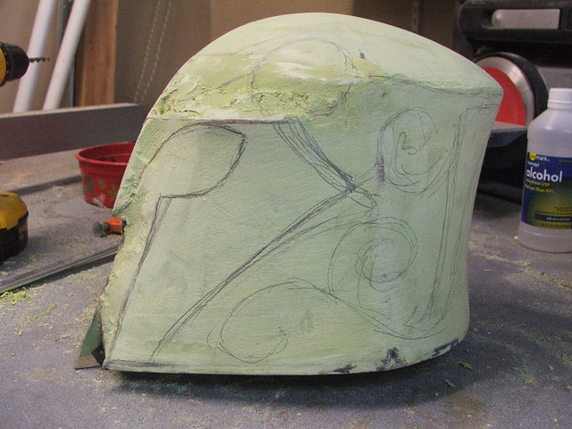
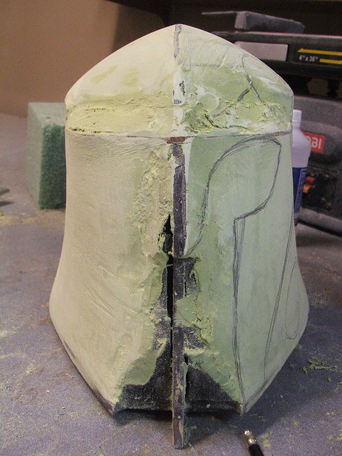
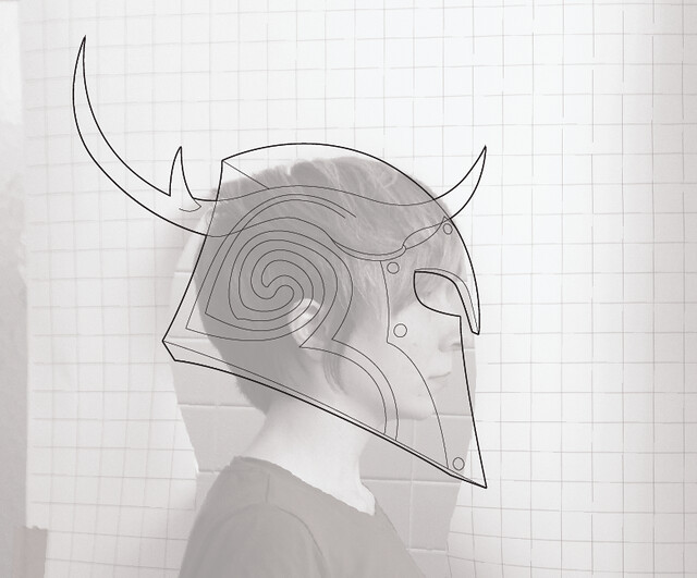
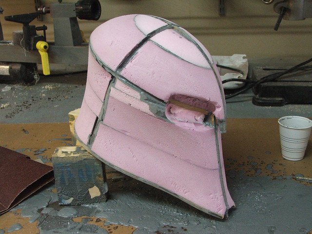
A little while into the sanding process, I noticed that the brow section was far too narrow. Using my blueprints, I traced out the brow section and transferred it onto some 3/16″ masonite. The gap below this was then filled with some florist’s foam. Florist’s foam is less reactive to solvents, so you can spread polyester filler directly on top of it without the acrylic coating needed on the pink foam.


Couple sketched lines to get the feel of where things are going. Getting better!
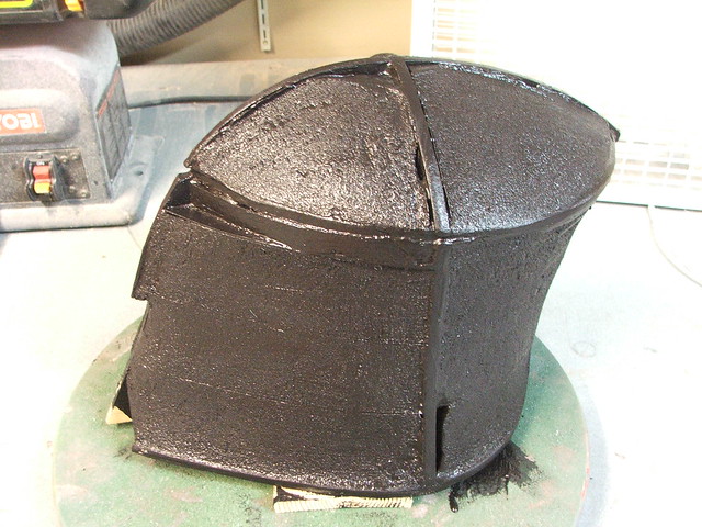
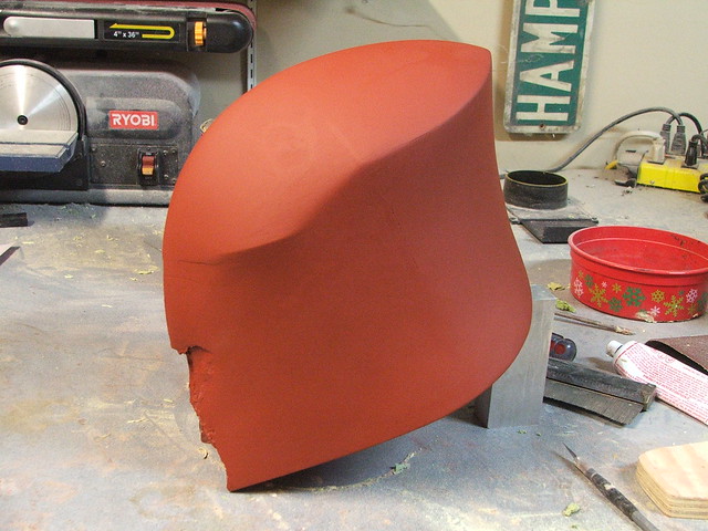
The shape was refined and smoothed with coats of filler primer and thin passes of more filler until the shape was sufficiently smooth enough.
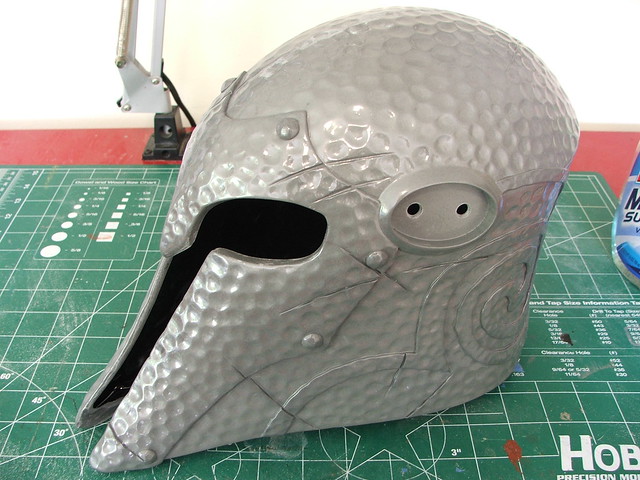
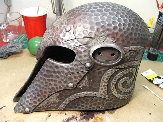
In the Female Draugr helmet, I took a dremel and carved out each “hammer dent” individually. Despite this being handmade, the end result still looks somewhat uniform and more than one person has likened the surface appearance to a golf ball.
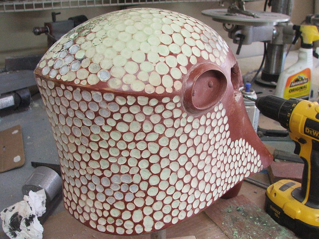
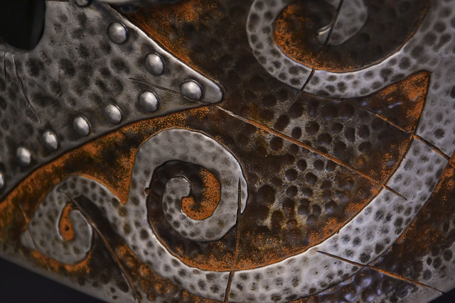
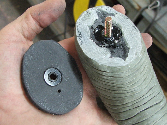
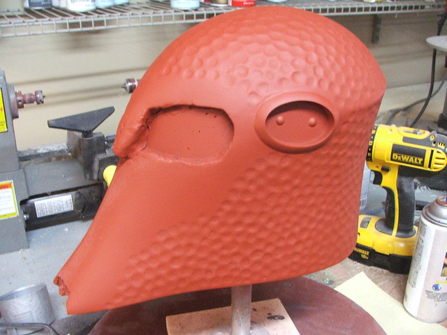
For Yngol, I took a different approach. The finished surface of the helmet was covered in a very thin layer of apoxie sculpt (about 1/16″ thick) which was then dented repeatedly with the backside of an engraving tool. This made the final surface much more random in pattern and depth and didn’t take nearly as much time as the dremel method from before.

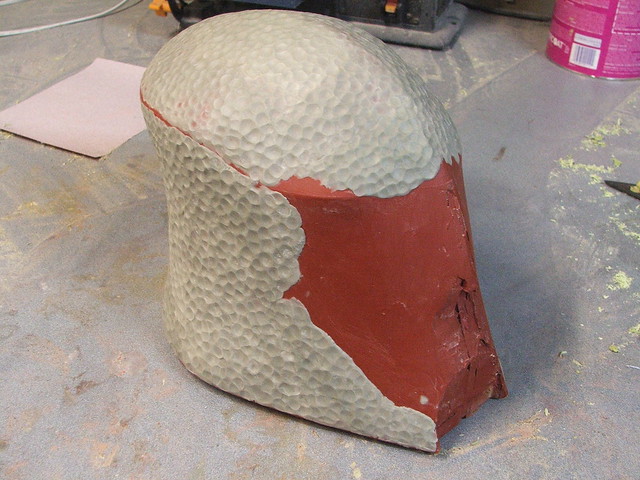
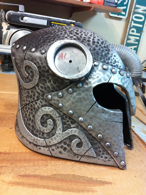
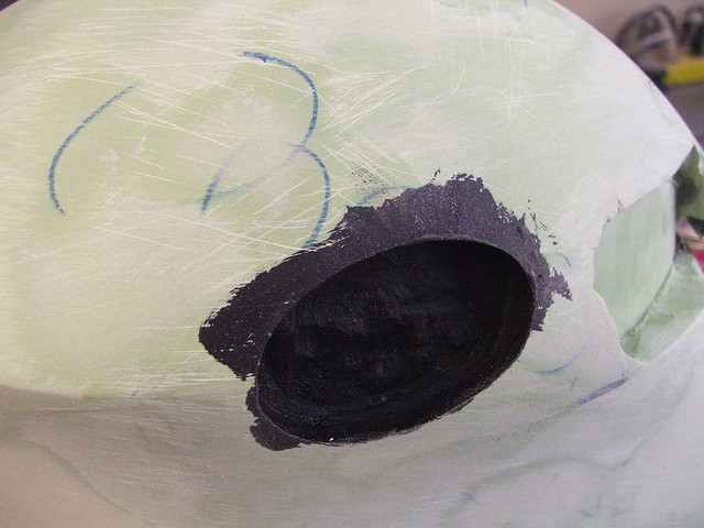
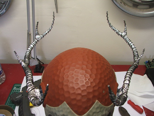
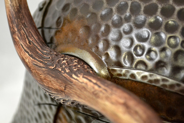
After completing the hammered texture, I attached the horn bases. These started out as vacuum formed styrene discs with acrylic rings glued to the helmet sides. After securing them in place, they got the same apoxie sculpt and hammered texture as the rest of the helmet.
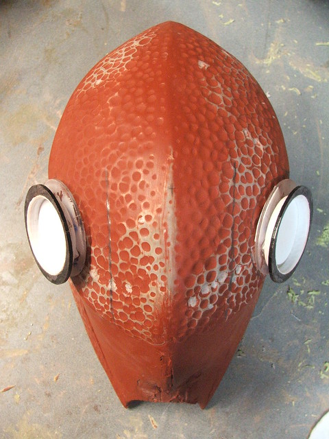
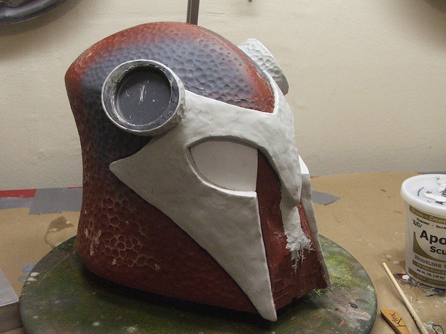
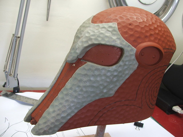
The face plate section came next. Styrene eye markers were trimmed out and glued to the helmet base as markers for where the sculpted elements needed to be positioned.
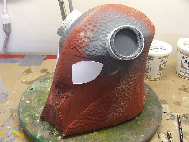
I don’t recommend the white apoxie sculpt to anyone looking to have clean, crisp details. I happened to purchase the wrong kind when shopping for sculpting supplies and my distributor is an hour from my house, so I was kind of stuck with it. The white apoxie has a more “fluffy” quality to it and won’t take an edge or very sharp detail well. In my opinion, the “natural” color is much better. After a lot of shaping with clay tools and a bunch of water, the faceplate was textured and left to cure overnight.

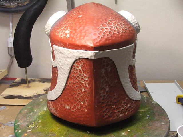
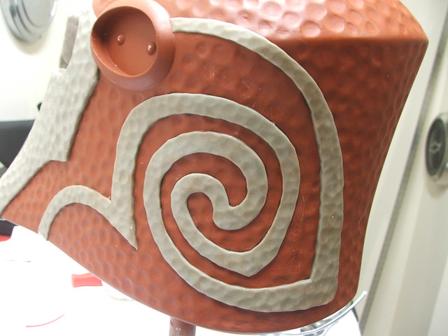
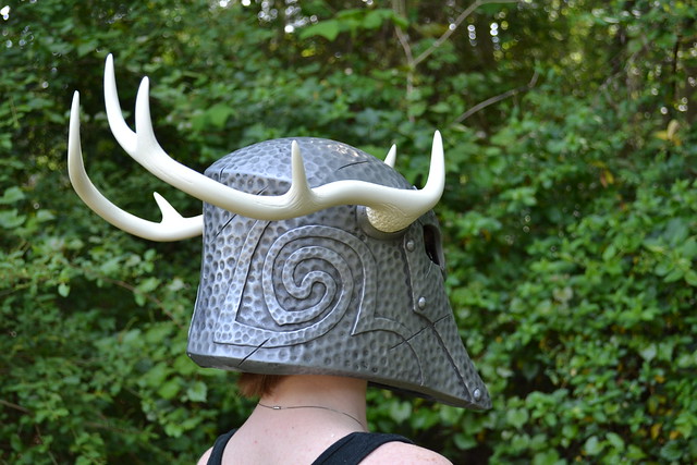
The side filigree received a similar texture. I trimmed out the pattern from some construction paper in order to transfer it to the helmet shape. This also made sure the trace lines on the left and right sides were as identical as possible.

Starting out… Pretty rough.

And cleaned up, with hammered texture finished.

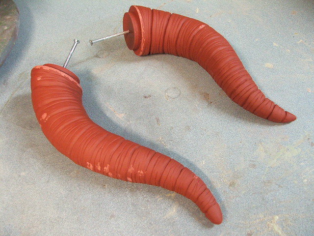
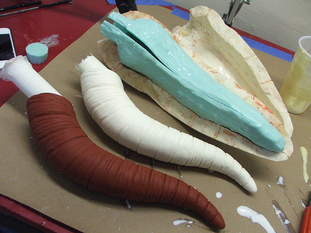
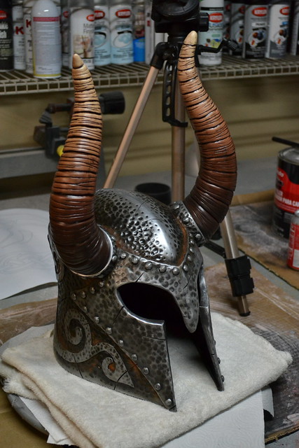
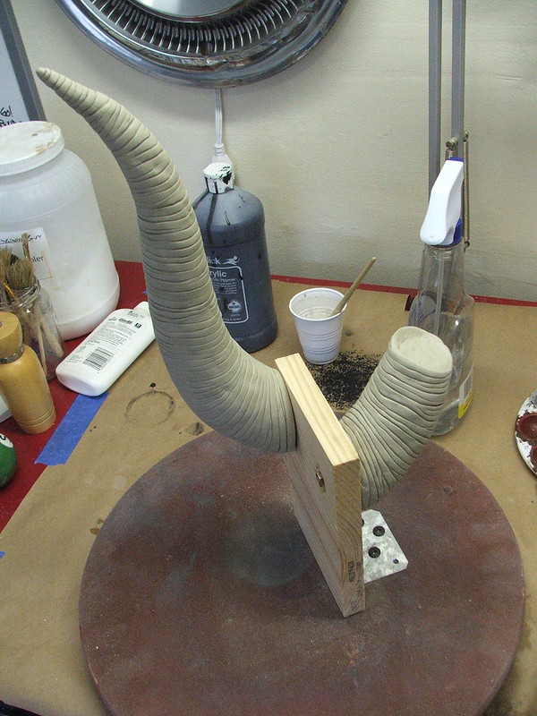
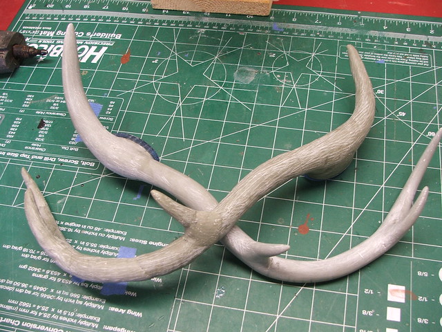
Next up (and again, I was just trying to burn through the white apoxie sculpt at this time, hence why I’m being sort of liberal in using it!) were the horns. These have a polystyrene foam base and are skinned in apoxie sculpt. Their base is an acrylic disc, which allows them to fit into the plug on the horn base. These needed very little sanding after a coat of filler primer.

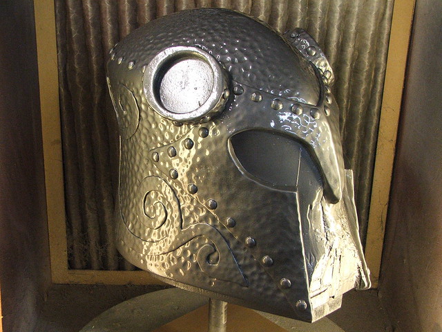
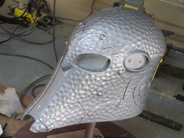
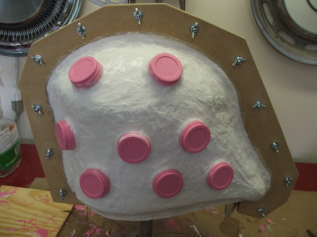
The helmet was painted in primer to spot any small issues that still needed filling/sanding, then the rivets were added. These are 3/8″ furniture tacks, and there’s over 50 of them in this thing.


A coat of primer, then a coat of gloss enamel, and it’s ready for mold making!

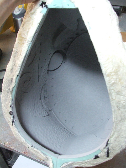
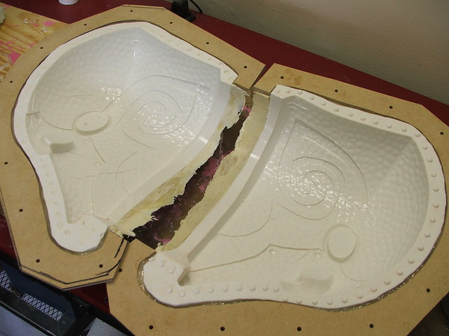
I don’t have many extensive steps of the print coat/thickened coats here – if you’re more curious about the finer points of molding a helmet, check out my Daft Punk Thomas helmet write up for more details there. The material used on this helmet is Rebound 40 – thicker than what I typically use, but I wanted to try something new.
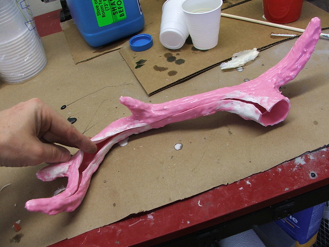
The horn molds are one piece with a slit up the inside in order to demoed the finished casting. This slit in the silicone is situated on a thickened channel to help make sure the two sections register properly when the mold is assembled. The horns themselves are cast in a thin coat of Smooth Cast 320, then filled with expanding foam in order to keep the weight down.

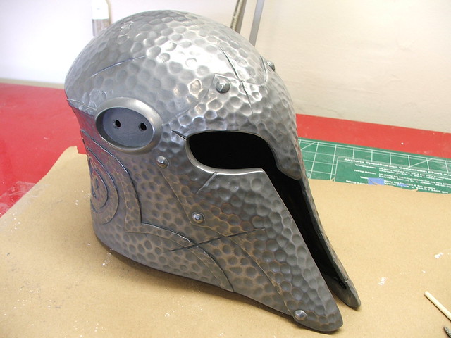
The helmet itself is cold cast in aluminum powder with Smooth On’s ONYX resin.
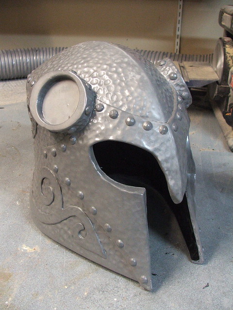
Cast parts trimmed and assembled!
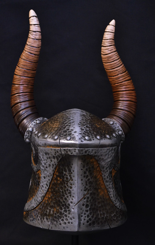
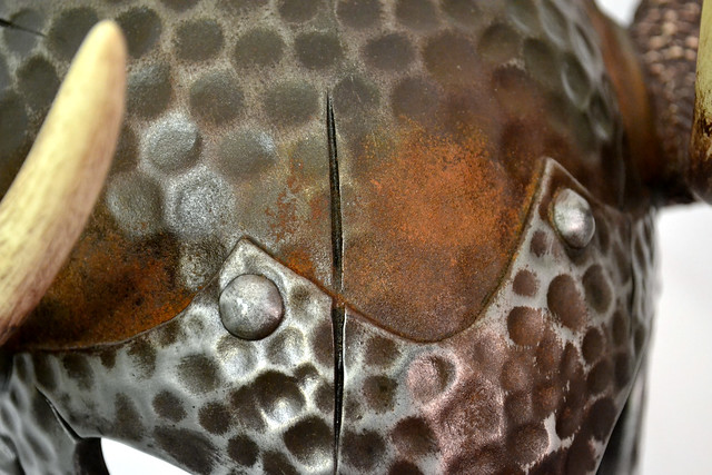
Cold casting powders allow you to buff the surface of your casting with fine grit steel wool in order to get a metallic shine. The helmets (I made 2) were buffed with 000 steel wool, then I added gouge marks and other lighter damage with my dremel tool.
Weathering these pieces was a mix of acrylic airbrush washes in black and various browns, followed by some heavier brush painted acrylics in the seam lines.
The helmets were rusted with ferrous iron powder. This was sprayed with a mixture of vinegar, hydrogen peroxide and salt, then left to cure overnight.

The horns were painted in a gradient using an airbrush and three different mixtures of brown. The base color of the 320 resin – an off white – meant I did not need to base coat the horns after sanding the castings.

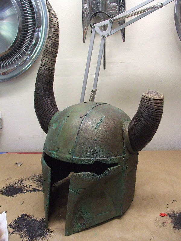
A few coats of clear later to protect the finish and weathering, and the project is complete!

My client got the better of the two helmets – mine was a test piece and is actually a fair bit thicker than the final production piece. A few segments of thin foam squares pad the inside of the helmet to the proper height.

A few detail shots:
More pictures of the process are available on my Flickr page. If you’re interested in seeing daily updates of my projects as they happen, then please stop by my Facebook and subscribe!

Thanks for reading!

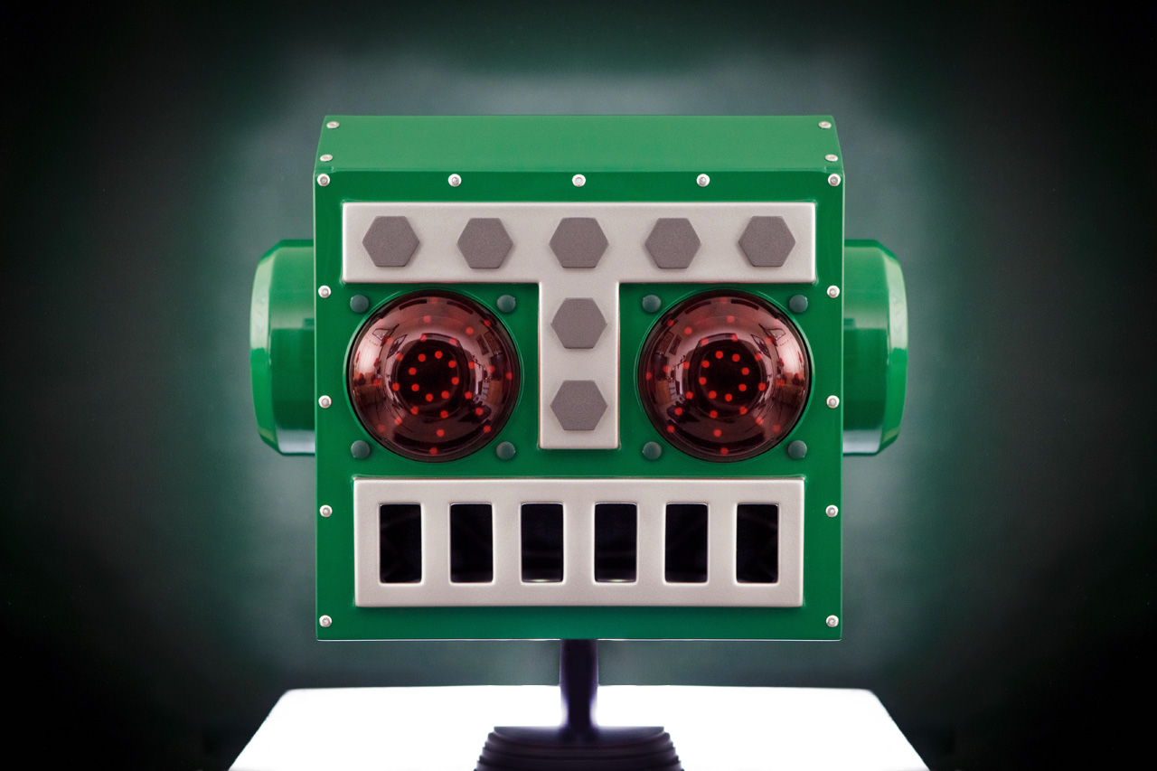
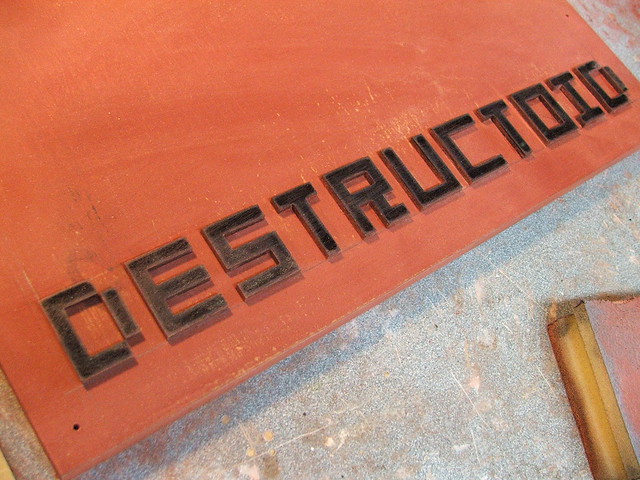
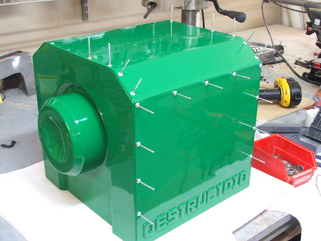
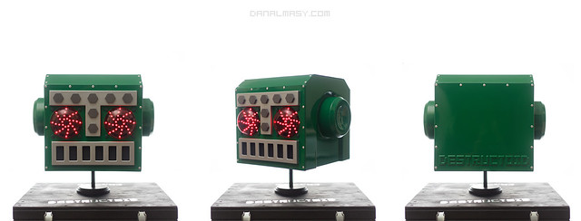
Mr. Destructoid Helmet V2
About three years ago when I was first getting started in the whole propmaking thing, the guys from Destructoid.com asked me to make a big mascot head for them to wear at conventions and such. I had no idea what I was doing, but the finished piece looked pretty good despite weighing 10lbs and being made from masonite and polyester resin.

This thing has been all over the world and has had the crap kicked out of it. The eyes were knocked out, battery cable torn out, at some point someone installed a speaker system inside it attached to an iPod. Its on its last legs after three years of game conventions and parties, so they’re after a replacement.
Re-imagined plans:
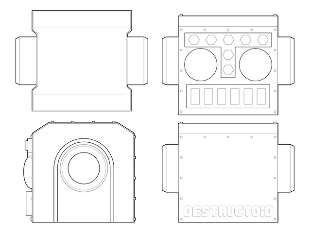
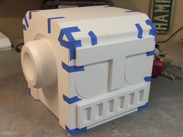
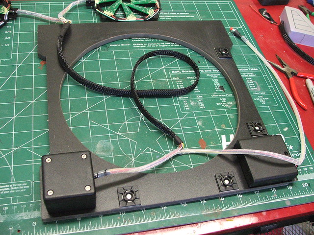
My plan is to make the new one out of all vacuum formed parts, and incorporate each element into the main buck so things won’t snap off. Ears will be connected to the sides, and the mouth/eyebrows will be connected to the faceplate. This helmet will also have LED eyes with 20 sequenced patterns.
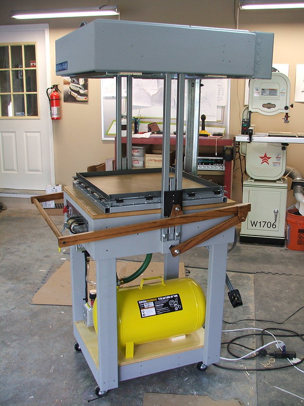
If you’re a regular reader of this blog, you might recall the Proto-Form Vacuum forming machine I built a few months ago. That machine was constructed specifically for this project! The large scale of this helmet combined with the thickness of the materials I’d need to be working with meant a new higher-end vacformer was in order. It definitely lived up to expectations, and has been a very valuable addition to my shop.
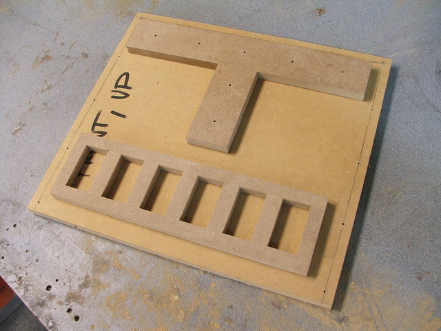
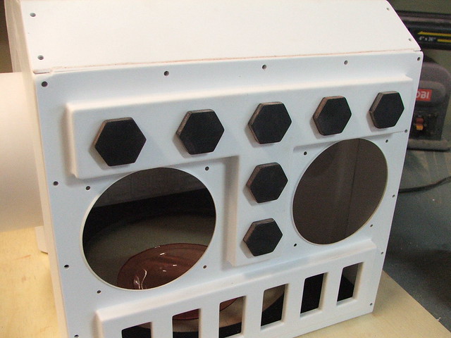
I started off by making some of the simpler forms from sheets of MDF. The faceplate and side panels were layered 1/2″ sheets with accent pieces cut to shape on a scroll saw. Since the side panels are symmetrical from left to right, I would only need to make one of these bucks in order to pull copies for both sides.
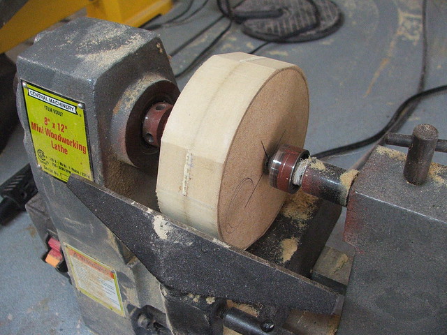
The large ear puck started out as a 2″ thick chunk of MDF, rough cut into an octagon before being turned on a lathe. The final piece has a hole drilled through the center in order to allow air to be pulled into the large divot during vacuum forming.
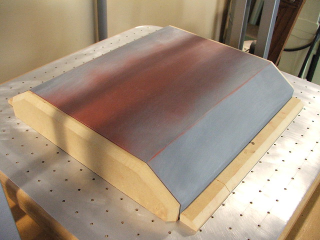
The top of the helmet would be a bit too thick to make out of a solid brick of wood, so I started by making a set of MDF spines that would have 1/4″ secured to it with brad nails.
After the outer “skin” was completed, I filled the interior cavity with expanding foam to make sure the vacuum of the machine wouldn’t crush the thinner wood.
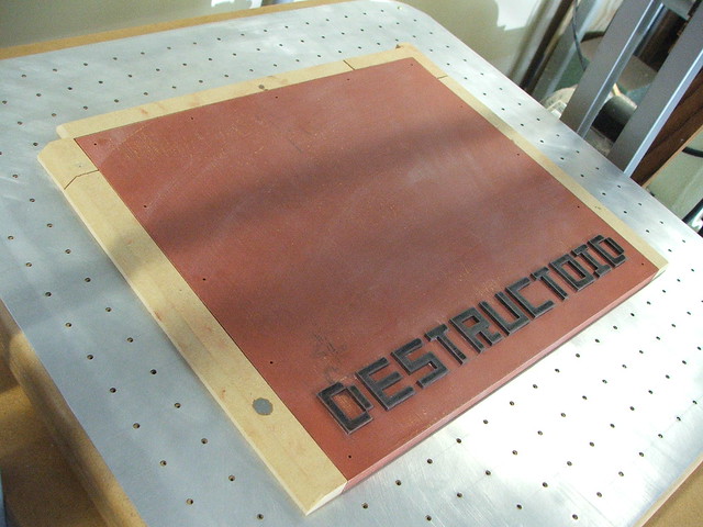
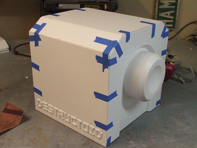
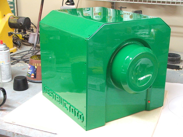
The backside of the old helmet had a riveted strip at the top, similar to the eyebrow section on the front. Mostly this was just to add some visual interest, but for the new one I thought adding the Destructoid name to the plastic would be a much more interesting look. The guys at Destructoid supplied me with their font, and I cut the logo out of 1/8″ acrylic on my laser cutter.
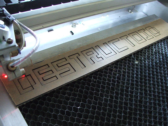
Using the negative space as a frame for the new letters, the acrylic was glued to the back side buck. I had to drill small holes in the corners of some of the letters to make sure the air would be sucked through them to give me a nice detailed pull.
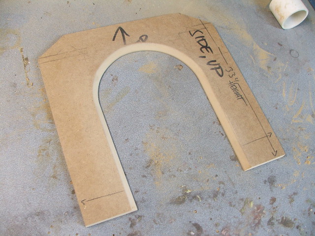
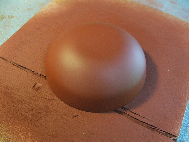
The last buck that needed to be made was for the large eye lenses. This, again, started as a couple laminated pieces of MDF. After a bunch of turning, sanding and filling, I had a smooth pretty dome.
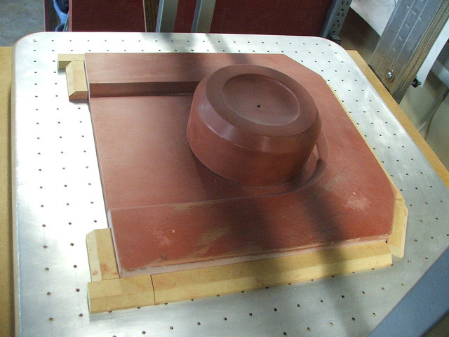
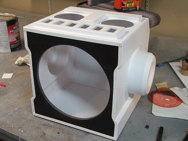
Onto the forming… almost! Before this, I made a series of drafts for the forms out of 1/2″ MDF. Pieces like these make it much easier to remove the finished part from the van formed plastic, and also make sure that you don’t get a lot of nasty webbing along your corners. I made these parts in several different lengths so the same set could be used for all the parts. The upper section of the helmet needed two large custom blocks made for the sides, however.
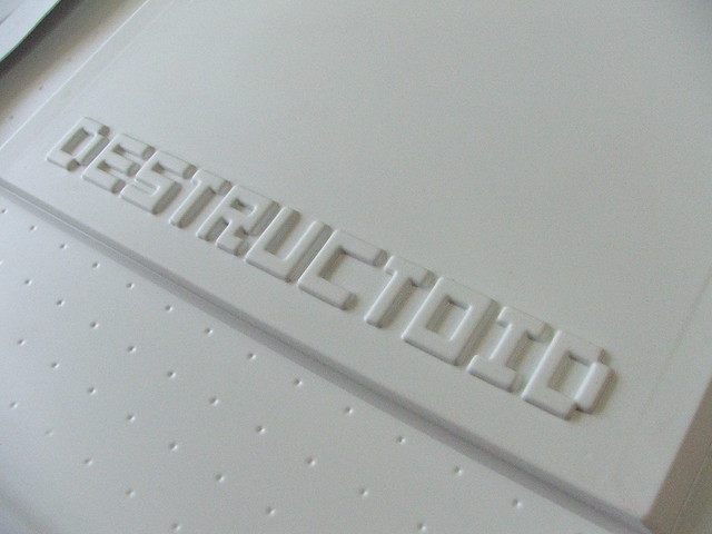
Plastic time! All of these parts were pulled from .10″ styrene. The detail I got on the letting was VERY impressive. I really love this new machine.
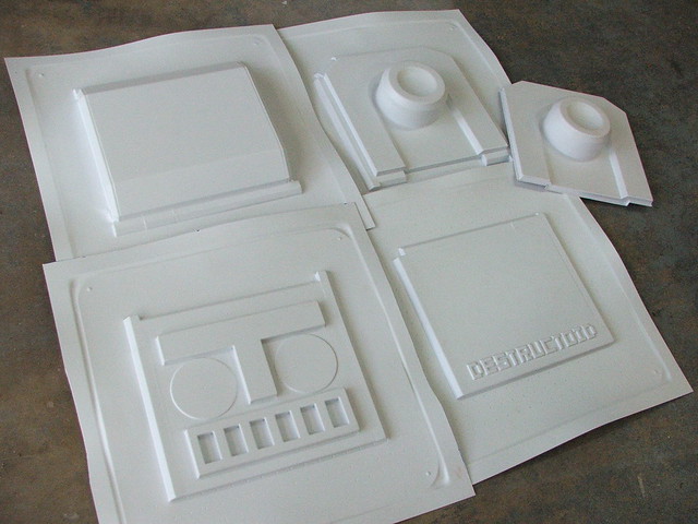
After trimming, I taped all the pieces together to see how things were shaping up. Pretty much exactly as I’d imagined, thankfully.
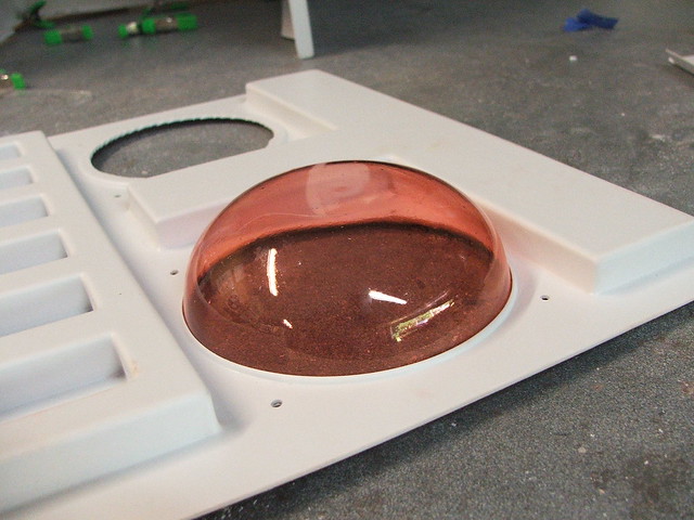
The eye pucks were pulled out of 1/16″ PETG plastic, on my old smaller vacuum forming machine. The wire grid there ensures you still get vacuum even if all the holes are blocked with plastic.
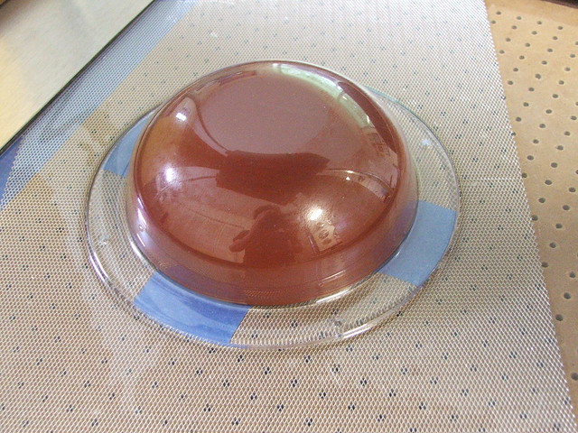
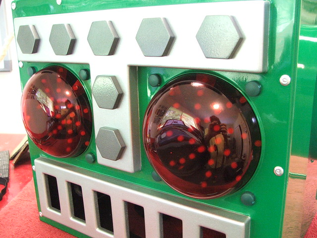
These clear parts were then dyed red with a material called “iDye Poly” I had one test piece, shown here, that I used to check fitment of the eye areas. I’d like to claim that that fine edged lip in the faceplate was entirely intentional, but it was just a very fortunate accident that happened to look cool!
The large bolt heads were trimmed from 1/8″ acrylic, and had a screw embedded in between their two halves to secure them to the helmet faceplate. The longer threads of the screws came in handy later when I was routing wiring around inside there; they allowed me to use some wire C-clamps and additional nuts to make sure all the wiring was clean and tidy.
At the base of the helmet, I added a reinforcing plate made out of 3/8″ sintra. This plate would eventually be the mounting plate for all of the electronics and wiring for the eyes.
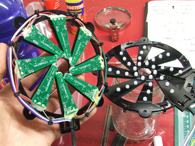
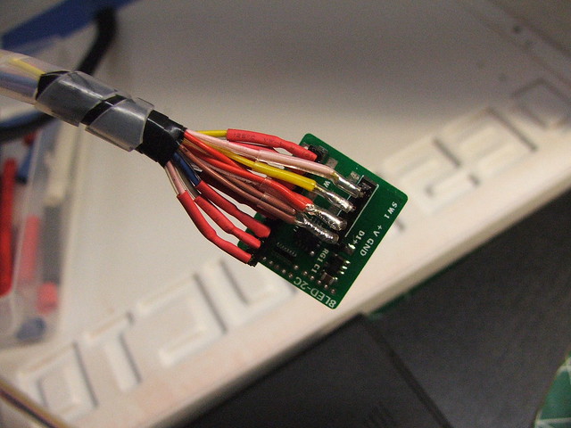
Speaking of wiring, it was at about this time that my circuit boards showed up. The boards for this project seem overly complicated, and they kind of are. I would have much rather made the entire “eye” board out of one PCB, but unfortunately the software I work with (Cadsoft’s EAGLE layout editor) has a small working area on the free version, so I had to come up with a different solution. Each segment of the eyes would be its own separate board, and these would all need to be wired together for power, ground and signal. More complicated, yes, but it works!
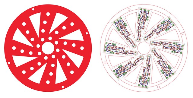
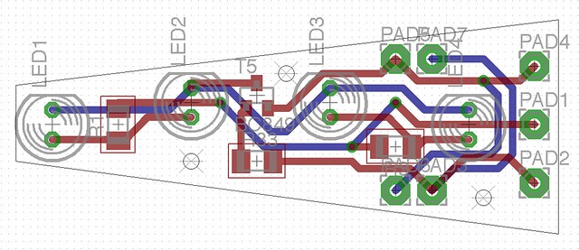
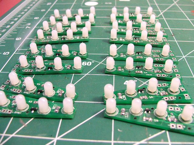
The soldered boards. Using SMD components helped me keep these fairly small, and the frosted red LEDs have a very nice full 180º viewing angle. Boards were printed at BatchPCB.com
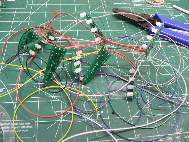
Wiring was… messy for the first few passes.
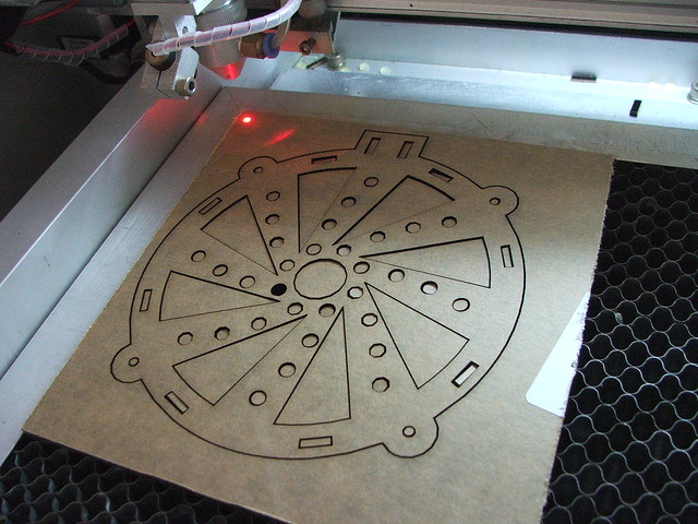
Here’s the LED holder being cut on my laser (I’m a bit spoiled with this thing, I know…)
And the assembled eye lighting rigs. There are holes cut in these to help the wearer have a bit more vision out of the helmet than in previous models. In the old helmet, you could only look out of the mouth section. While the LEDs reflecting against the lenses does make looking out of the eyes a tad difficult, it’s better than having a big solid wall in front of your face!
First test fire!
This is the little brain chip that makes all the animations possible. This was created by a very talented electronics guru, Donnie James. There are tons of animation sequences this little chip can do, and this helmet has about 20 patterns programmed into it. If you’d like to order your own, you can find a link to his products here.
More wire mess.
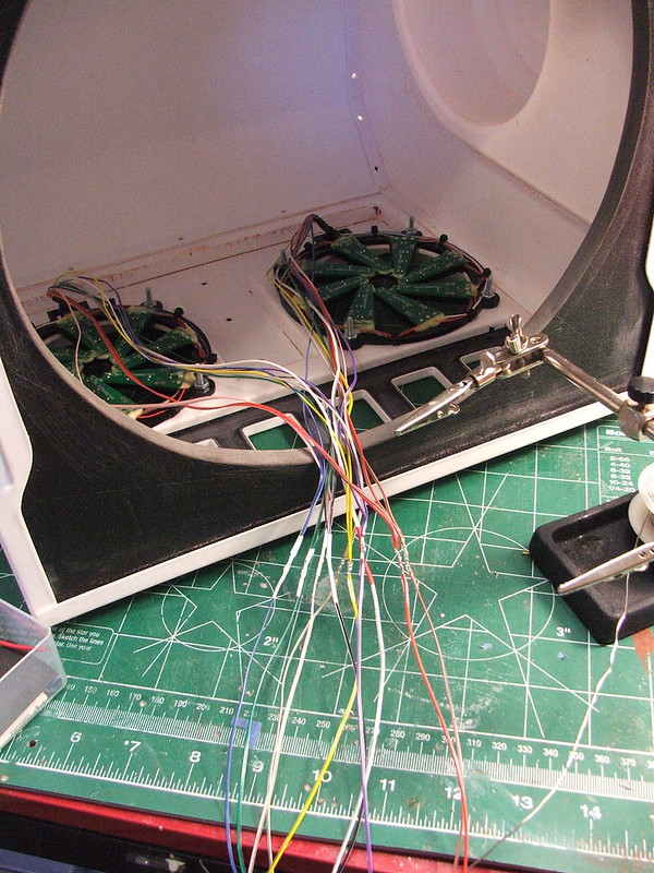
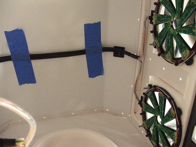
The eyes installed!
After a lot of wire wrap, zip ties, and conduit mounts, things start to look cleaner inside the helmet. I guess it’s a hold over from my days doing car audio installation, but I have a sort of mania about wires being clean and routed properly.
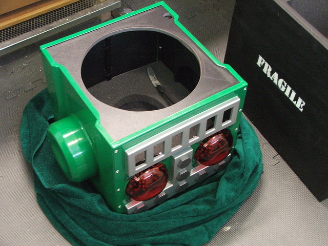
The baseplate section with the brain box installed (lower left) and battery tray (lower right.) The helmet runs off 4 AA batteries and should get about 20 hours of life out of one set.
Onto paint! The assembled helmet was stripped of all the electronics and internals, leaving me with a blank shell that got a couple coats of primer. The helmet right now is just held together with superglue around the seams, but this will be strengthened later after paint with some rivets along the various holes you can see here. I really recommend anyone doing projects like these to install all your mounting points and drill all your holes before you put the final paint coat on the project you’re building. The likelihood of scratching a nice finish when you’re trying to figure out how to mount a component is too high – I know I’ve done it!
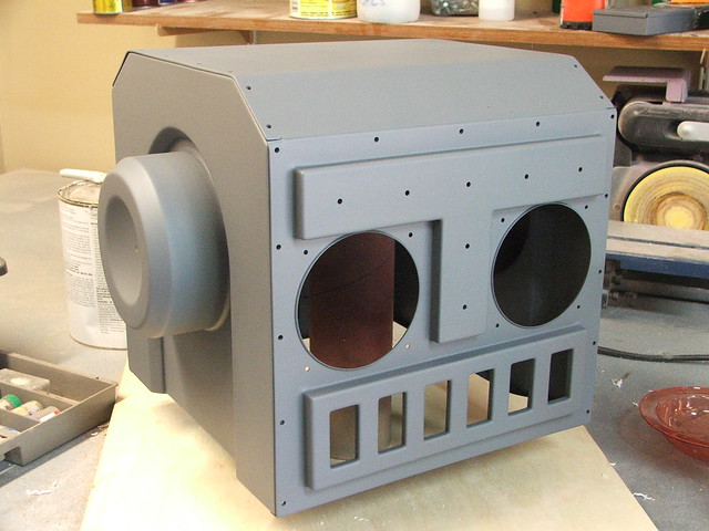
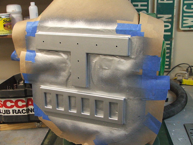
Silver accents being masked off on the faceplate.
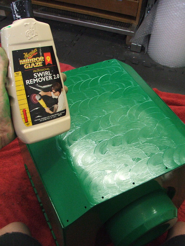
The green paint was sprayed quite thick, then allowed to cure for 7 days. After this, the entire helmet was wet sanded down to 2000 grit sandpaper.
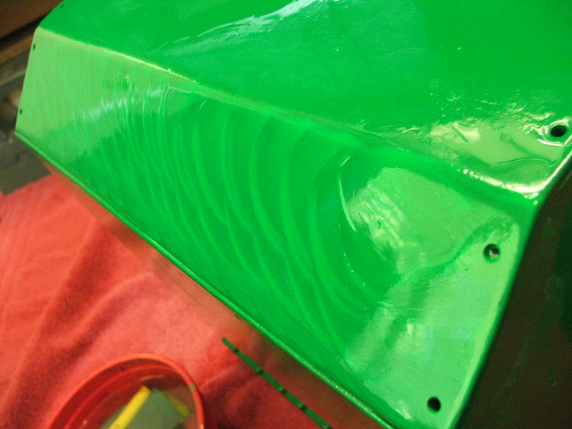
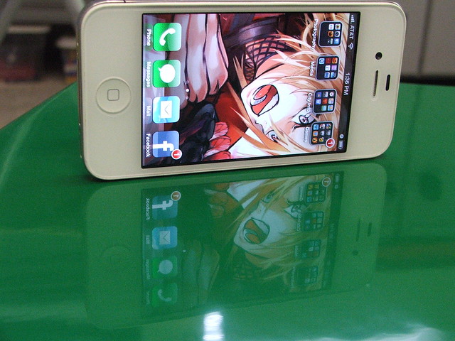
After the wet sanding, the entire piece was buffed with swirl remover, then given 5 coats of Meguiar’s Tech Wax. The results are very shiny!
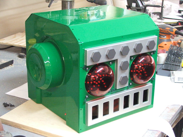
In this shot you can see the “little red button” on the lower front side of the helmet near the ear recess. All of the programming and control of the illumination board is done through this button. You can change animations, speed up or slow down, turn on power saver mode, etc.
The last step after re-mounting all of the components was to add the rivets to the seams to strengthen the structure a bit.
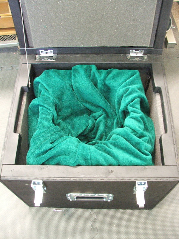
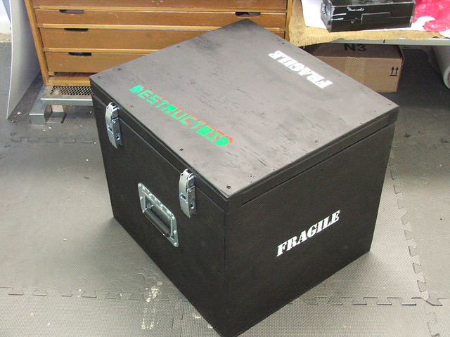
To make shipping and transporting this bucket easier and safer, I also built a custom shipping crate for it. My friend Cathy over at God Save the Queen Fashions even had some scrap green terrycloth around to make a protective shipping sack to further protect the paint and finish. The crate weighs about 10x what the helmet does, but it’s really secure in there!
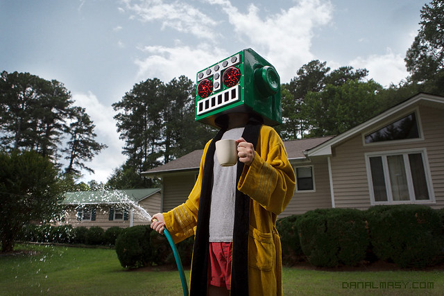
The final result! Thanks (again!) to my friend Dan Almasy for doing the great photography here.
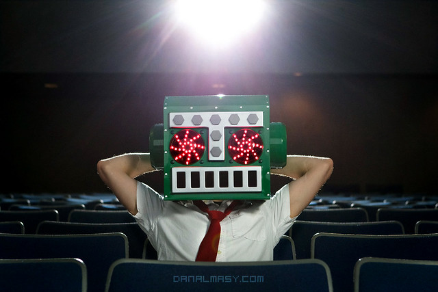
The finished piece weighs just over 3lbs and is quite comfortable to wear. There’s a foam pad at the top of the helmet and it is secured to the wearer’s head with an adjustable chin strap.
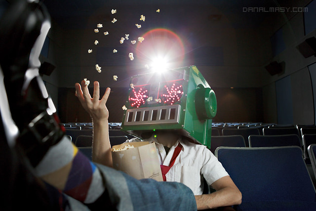
I really recommend you check out the high res version of the pic below – this shows off the finished result really well!
Thanks for reading, and if you’d like to see more higher resolution shots of the process, check out my Flickr page.
Dovahfett for Make-a-Wish
Several months ago I got an email from a my friend Art Andrews asking if I would be interested in taking part in a very, very cool project. At Star Wars Celebration, a convention held in Orlando, there have been past exhibitions where artists were given Vader and Stormtrooper helmets, then allowed to modify them to whatever they wished. Afterwards, the helmets were auctioned off for charity to benefit the Make-a-Wish foundation. The organization heading this up for Star Wars Celebration is the As You Wish Helmet Project.
This year, at Celebration VI, 40 artists were asked to portray their interpretations of helmets belonging to Clonetroopers and Boba Fett. I was asked to modify one of the Fett helmets.
I should note that I am in some terrifyingly professional company here. This project will eventually feature helmet redesigns from artists like Sandy Dhuyvetter (who painted three of the original screen used Boba Fett helmets) to full scale production giants like Legendary Effects (who’s work you may have seen in The Avengers, Thor, Ironman, etc) and WETA Workshop (Avatar, The Lord of the Rings, etc.) Intimidating, but also quite an honor to showcase my stuff next to theirs.
I received the helmet blank casting in the mail – this is a reproduction from a screen used piece, and many of the iconic marks can be traced back to original paint and weathering. Some people may balk at hacking something so accurate to shreds, but it was actually pretty fun!
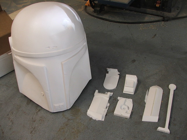
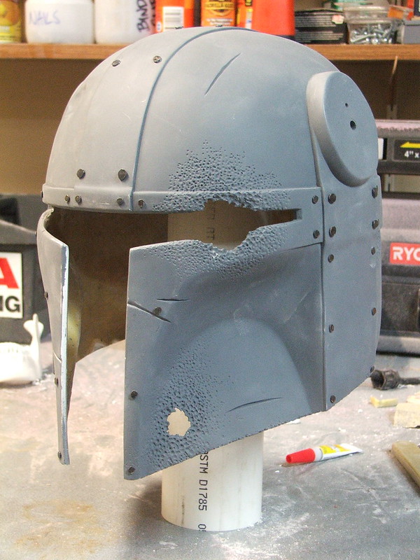
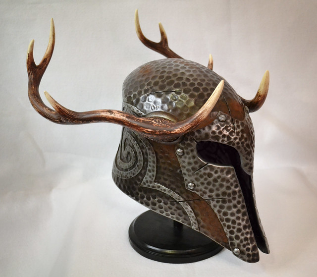
I started out by marking off where I would cut, trim, sand down and add panels. If you couldn’t tell from the image above or the title of this entry, I would be making my helmet follow an aesthetic similar to the helms in Skyrim. I’ve been playing a lot of that game over the past few months, and I guess it has made me want to bolt horns to everything.
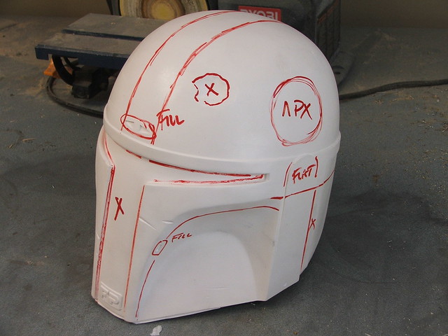
Because I’m a bit of a jerk, I decided to make a bit of a jab at the Fett helmet following by migrating the iconic “dent” to the wrong side of the helmet. Personally, I’ve always thought someone would take the time to hammer this thing out, but I guess Boba is a busy man. (As a side note, I briefly considered molding the dented area and constructing a helmet made up of nothing but hundreds of dents grafted together.) Cut out areas were taped back in place with tin tape, then resined back into position with some chopped strand fiberglass mat. Other ancillary bits were shaved flat or filled in to fit the final design idea.

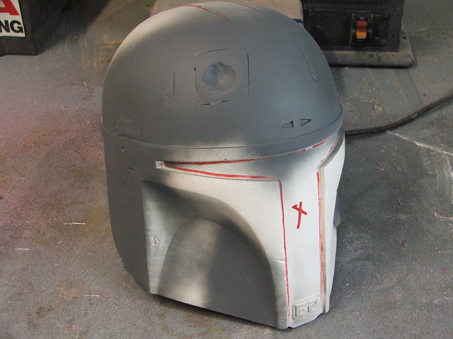
A bit of bondo and filler, and the modifications started to blend back into the helmet shape.

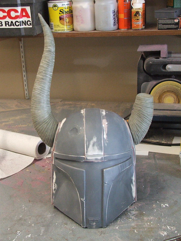
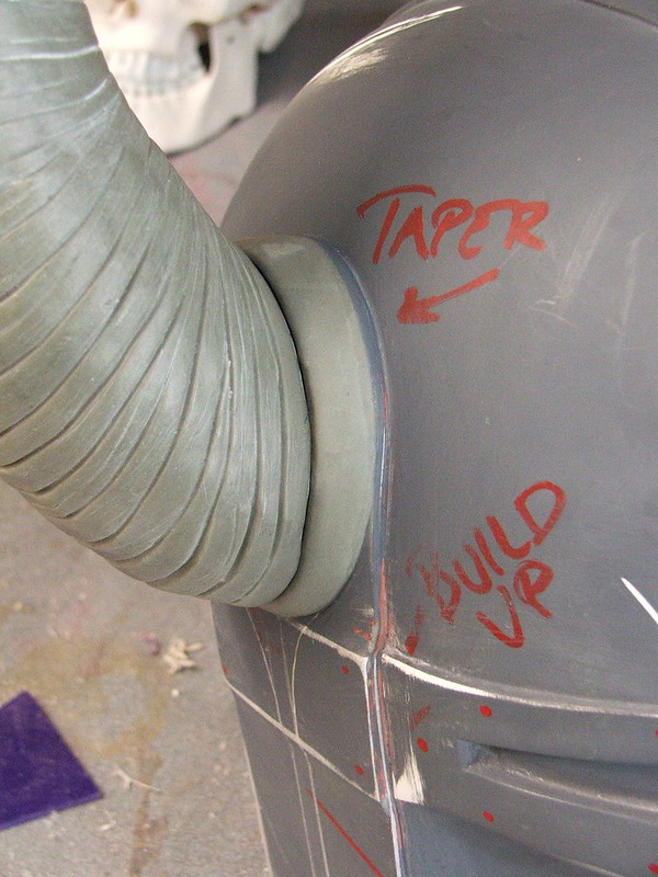
Lines were scribed for the raised helmet frame sections, then styrene plates were heated to shape and glued to the helmet base.

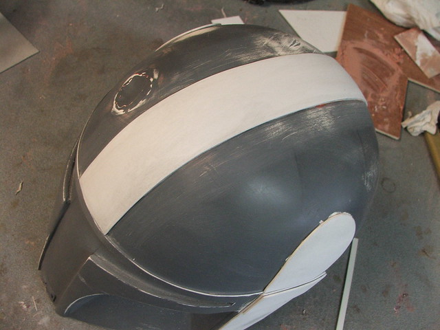
I wanted the visor area to look like a band of metal that went around the base of the helmet and riveted to the dome. I had to extend the back line with another piece of styrene to make this look the part, then fill in the resulting gap with filler to blend it into one shape.

Apoxie sculpt was used to blend the styrene into and over joint sections to give the raised areas the illusion of sheet metal bent over underlying shapes.
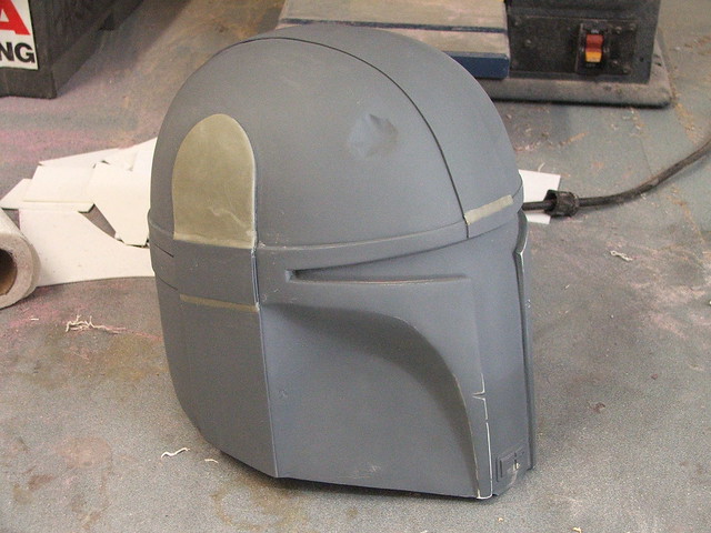
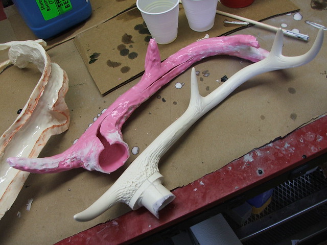
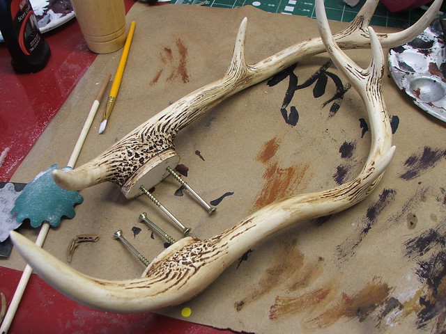
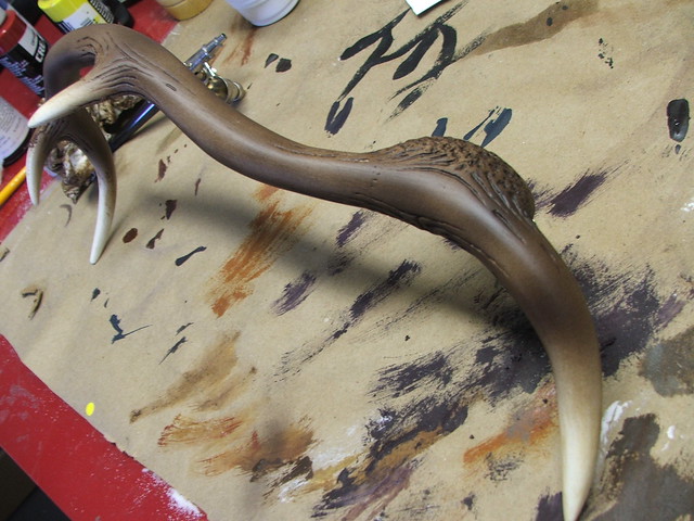
With the base shape starting to come together, I needed to shift focus and start work on the horns. My idea was to show one of these cracked in half, and to have the rest of the helmet display similar amounts of damage and neglect. I wanted a piece that looked like it has just been unearthed and put on display.
The horns started out as pink insulation foam, trimmed with a bandsaw, then shaped on my belt sander. After grabbing one and snapping it in half, these were coated with brushed-on urethane resin and rough sanded.


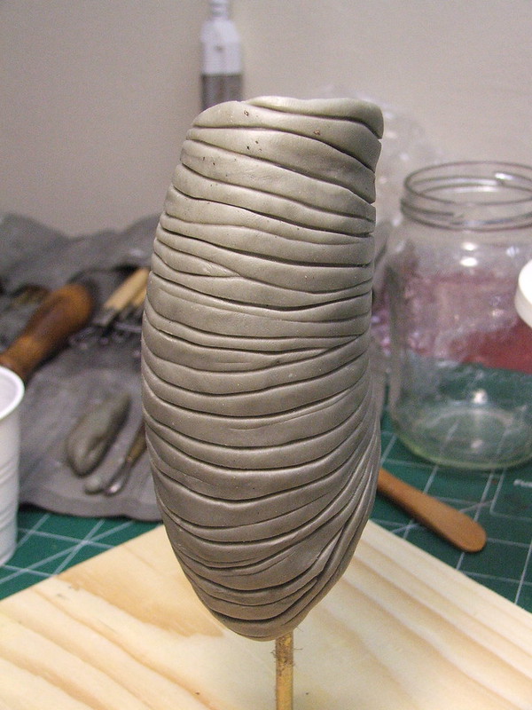
The horn texture was made with more apoxie sculpt, first layered over the entire horn, then scribed with varying depths of lines to give them a more organic feel. I don’t get to work on a whole lot of organic stuff, and while I admit I’m still learning how to get these sorts of textures to be convincing, this was a really fun step in the process.
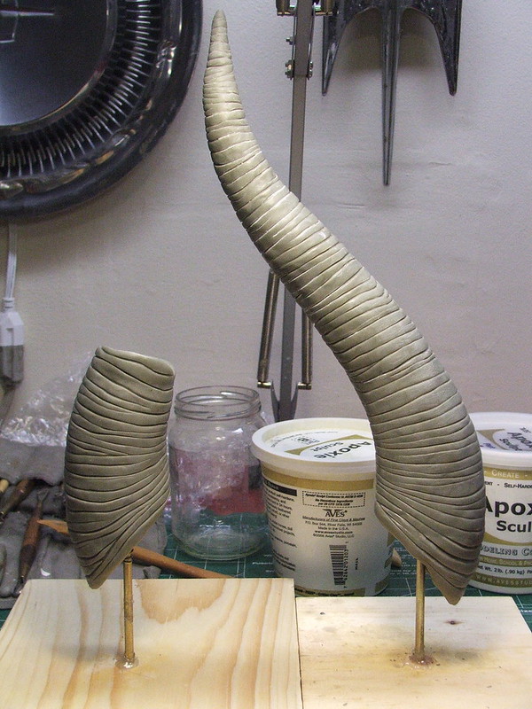
To affix these to the helmet, I drilled a depression into the foam in the horn, then inserted a threaded rod. This chamber was then filled with casting resin to secure the rod in place.

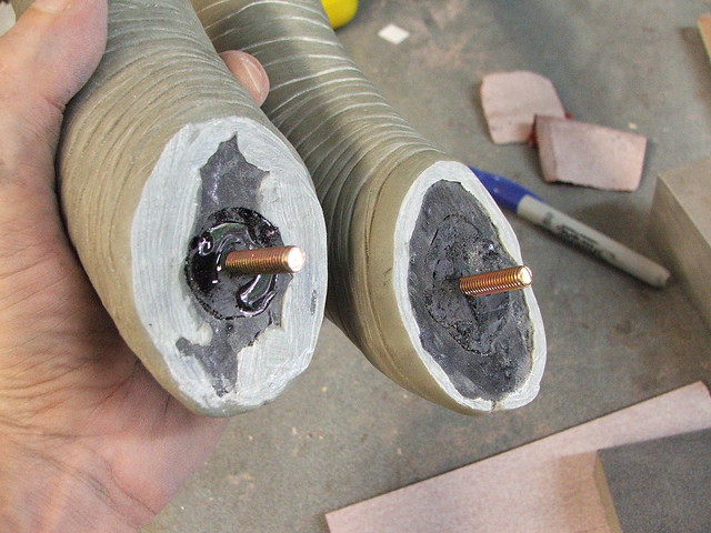
Drill a couple of holes in the sides of the helmet, and we’ve got horns!
For the horn base, I started by cutting a disc of sintra and heating it until it conformed to the contour of the horn itself. A dremel was used to shave down the perimeter so that the plate matched the horn exactly. These plates were glued to the helmet, then blended into the base with more apoxie sculpt. I also added a small pin to the base of the horn to act as a registration key so the horn will always be mounted in the same position.

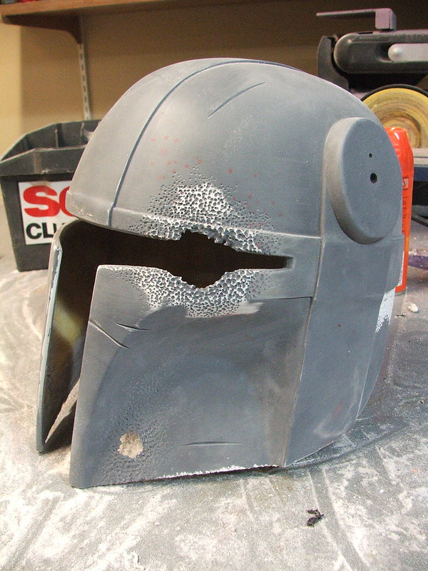
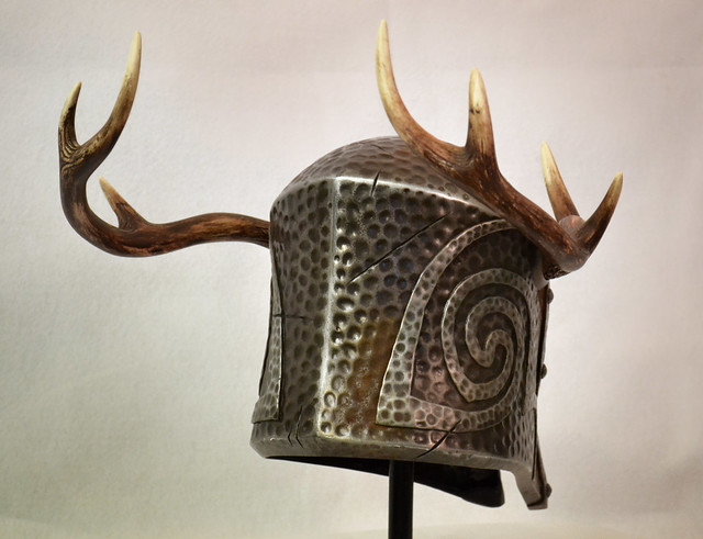
With the base form complete, I set about weathering. I wanted this thing to look old. Old, and very beat up. Using a dremel tool with a couple different ball engraving bits, I started hacking into several spots and building up a “corroded” texture where it looked like the metal had been eaten away. For the spots where the texture breaks through the surface, I sanded away from the back side to create an uneven organic opening.

This method was repeated in several areas around the helmet.
Carpet tacks were used to simulate rivets on the bands of the helmet. I used two different sizes to vary the appearance a bit. Pre-drilling these is a necessity. I also trimmed off the pointy bits on the inside.
The ball engraving bits were used again around the perimeter base of the helmet, along the edges of the bands, and next to the heavy gouges to give more texture.

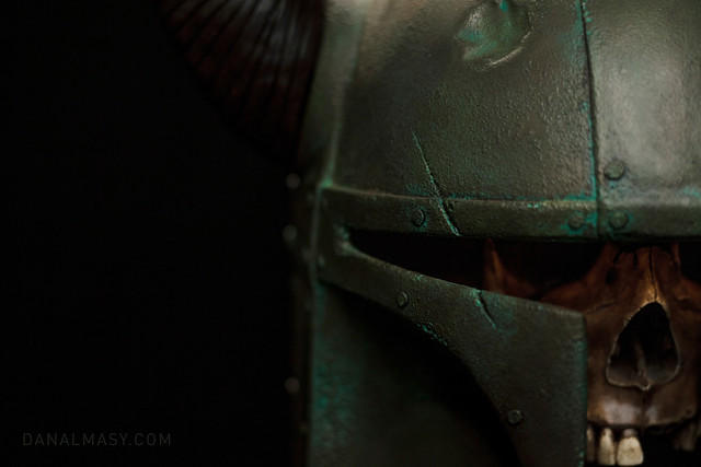
At some point a while ago, it was decided by some friends and me that a skull mounted inside the helmet would be a perfect finishing touch. Since I’m still getting my footing with organic sculpting, I opted to purchase one to modify. Mine came from eBay, and its original purpose was to assist in educating future dentists. Not today, buddy.
I started by cutting out several of the teeth and removing the lower jaw and mounting points. The teeth were molded as one part, so I had to cut them into sections then grind down the remaining plastic.
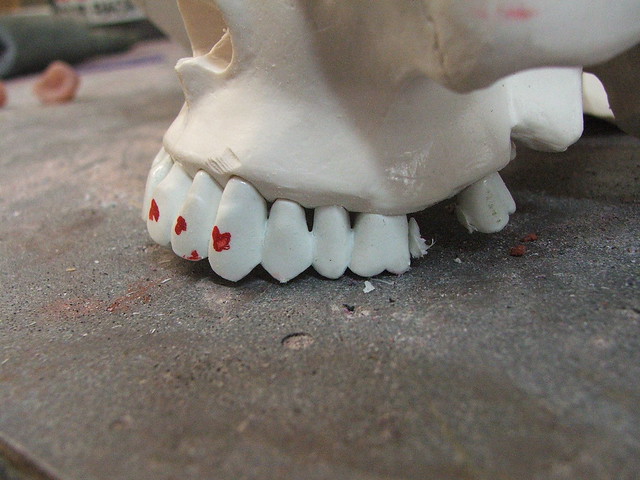
After a bit of thought, I eventually decided that Mr. Skull needed to have a gaping cavity in his temple that would line up with the large crater missing out of the visor. That was a bad day for him. To make up for it, I decided to glue his head back together – the yellow line in the shot below is a bead of epoxy where the skull has originally been sectioned into two parts.

Two holes were drilled in the crown of the skull to act as mounting points. These line up with a sintra “spine” that has two bolts embedded into it, epoxied on the top inside of the helmet.

Weathering the skull was a blast. Lots of brown and yellow washes, the older the better. I would constantly forget I had done this and spook the hell out of myself when I walked into my shop to see this creepy thing staring at me.

With the skull weathering complete, I started on the helmet. Admittedly, this was a new attempt and everything from this step on was pretty experimental to me. I had done some tests on scrap plastic though, and felt at least halfway confident I wouldn’t ruin all my previous work.
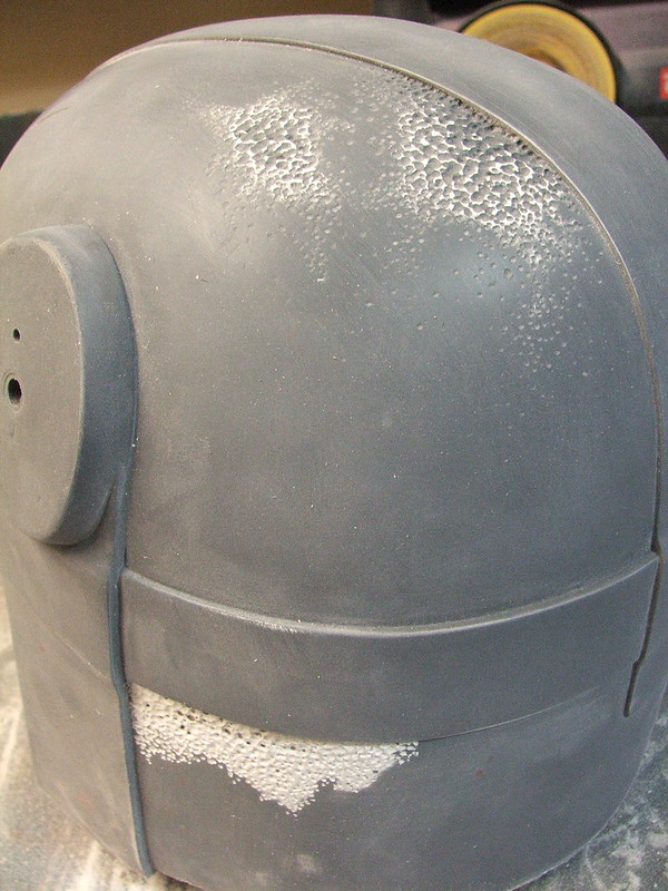
I started by taking black acrylic paint and mixing it with cabosil to make it thicker. This was sponged over the helmet using an organic sea sponge to build up texture. I taped off the bands for the first pass and textured them later so they would have a differing pattern than the surrounding surface.

This texture got a coat of gray primer, then a quick scuff with a sanding sponge to knock down any pointed high spots.

After allowing to dry for a couple days (acrylic this thick says spongy for a while) the helmet got a basecoat of copper/brass paint. This is actually a mix of 5 different cans of spraypaint – from a nearly black-brown to a reddish copper – that gives the finish a mottled mix of colors.

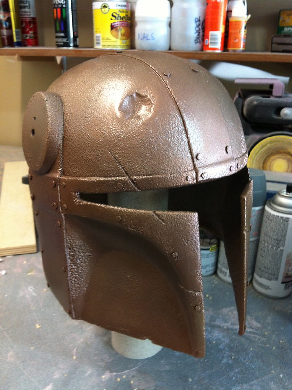
Weathering began once this was dry. I started by sponging on a pale green wash of acrylic over the whole helmet, concentrating on the deepest areas of weathering.


This was followed up with a coat of satin clear to seal in the acrylic.

Afterwards, the helmet got a wash of dark browns in the seam areas, followed by a very bright teal/green along the seams and heavy pockmarks. The green was again done with the sea sponge.

For the horns, I started with a coat of textured off-white. I also made a mounting plate that secured to a lazy susan I use for painting in order to make the weatheirng easier.
These got several washes of brown and black, deeper in color at the base and fading out as they went up. After they were finished, the horns were sealed with matte clear. For matte clear, I prefer Krylon #1311.


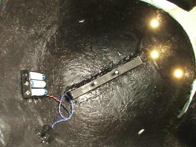
After mounting the skull inside the finished helmet, it seemed like the darkness of the helmet was obscuring all the weathering work I’d done. The solution, of course, was LEDs!
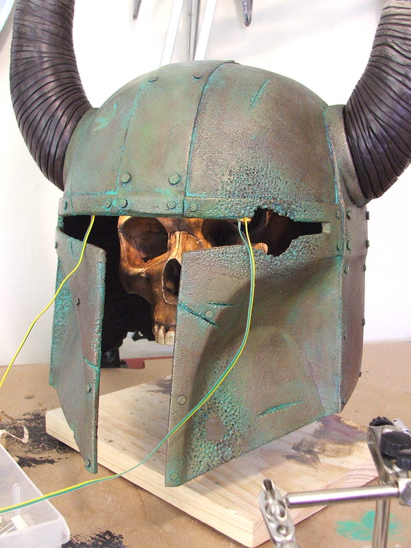
Three warm white LEDs were mounted to the inside of the upper brim of the visor to illuminate the skull when mounted in position. They are powered by 3 AAA batteries and controlled by a toggle switch in the back of the helmet. As much of the wiring as possible was painted flat black.
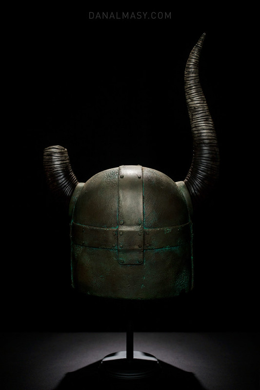
My very good friend Dan Almasy volunteered to do the final photography on this piece, and the photo session wrapped up just a few short hours before the helmet went in a shipping crate off to the auction handlers.
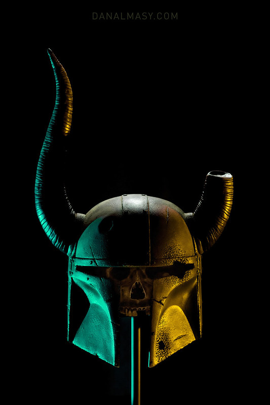

I am extremely happy with the weathering on this, and it was an excellent opportunity to be able to test out some techniques I haven’t had the ability to try before.

If you’re at Star Wars Celebration, stop by the display and say hi to Dovahfett!

More pictures of the build process and final result (in huge resolution!) are available on my Flickr page.

Be sure to visit the As You Wish Helmet Project on Facebook to stay up to date with these helmets. The final build will be available for purchase on eBay in the late summer! I’ll have an update at that time here as well as on my own Facebook page.
Thanks for reading!
All of the products listed in this write up are the products that I use and recommend. They are provided as Amazon affiliate links, which help support Volpin Props.

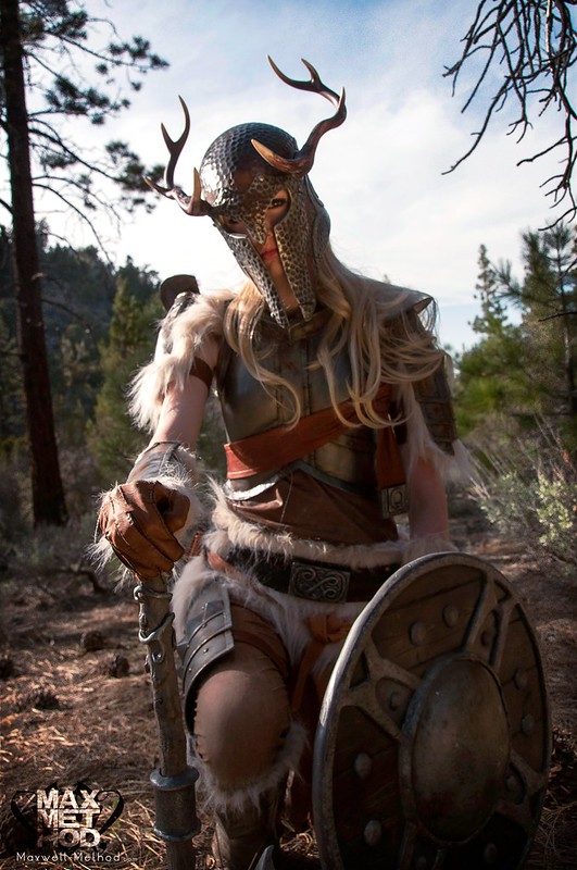
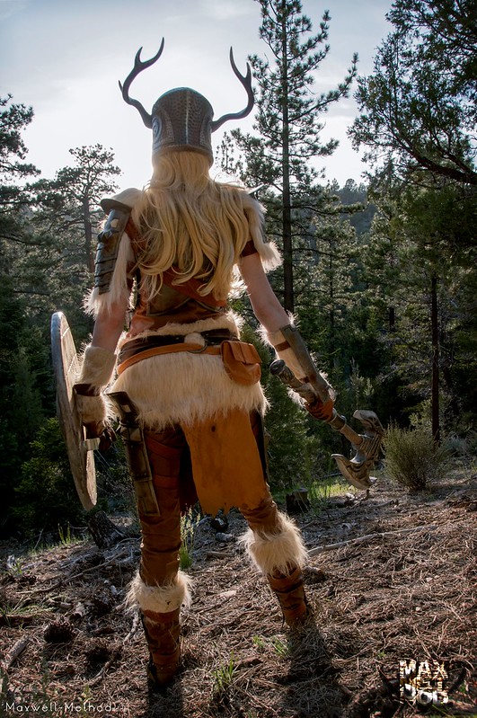
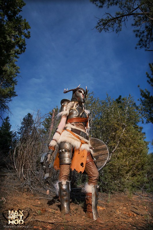
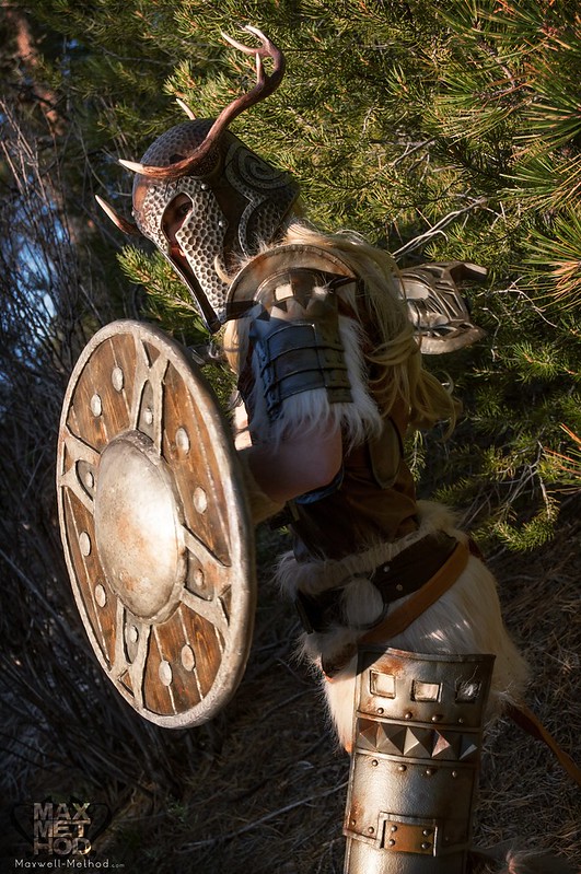
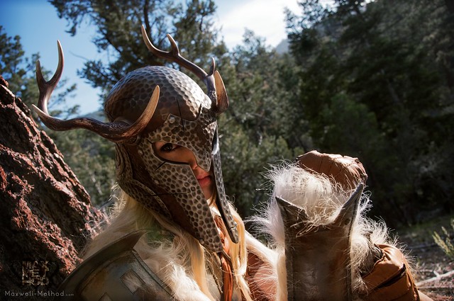
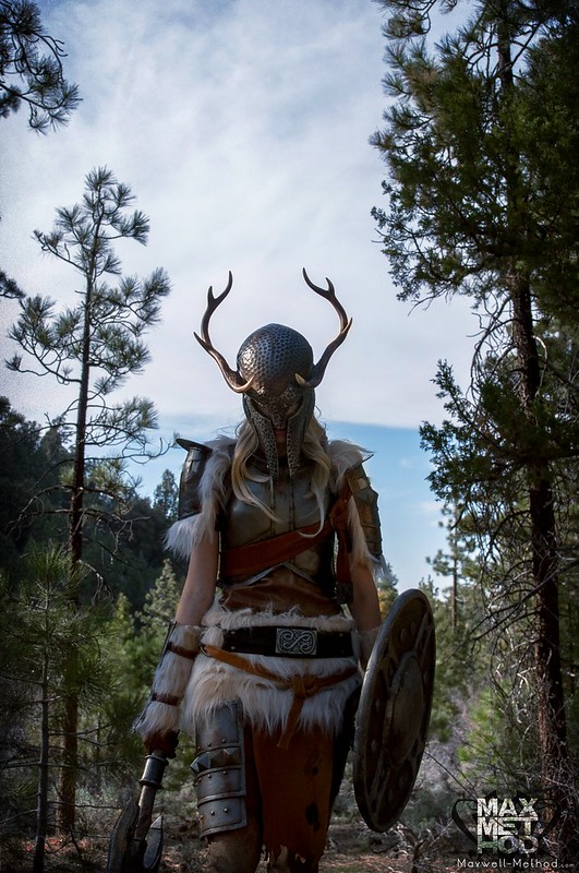
Nord Helmet photoshoot with Manzi DeYoung
About a month ago I was wrapping up my Skyrim Female Ancient Nord/Draugr Helmet project, and posted some of the progress over at my facebook page. One of the people commenting on the progress had a profile picture of them wearing a fantastic Dovahkiin costume, which got the gears turning…
While finished props sitting on a white background are always nice for a simple portfolio piece, I had to see what my helmet looked like with a complete set of armor!

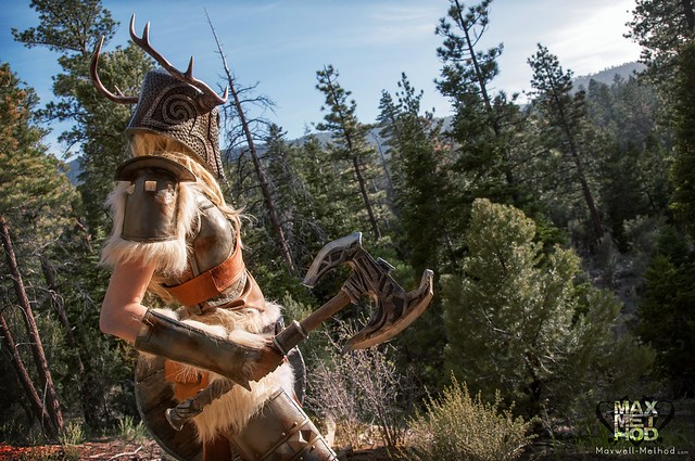
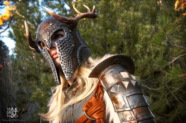
Manzi DeYoung is the model and builder of the Iron Armor/weapons and Dragonborn costume shown here (armor and cloth work? This lady is going to take all my clients!) After following her comment to her own facebook fanpage, I dropped her an email asking if she wouldn’t mind doing a shoot with her armor and my freshly finished helmet. I got a very enthusiastic “yes” and we were off! All photography work is credit to Max Song.

A few medical issues prevented the final shoot from lining up with my blog post about the helmet build process, but the results were worth the wait and I think its better to showcase cool pics like this on their own post instead of after along build log anyways.
I think its worth clarifying a second time just in case anyone missed it: The only thing I made here is the helmet. Manzi is a fellow prop maker out on the west coast, and the armor she’s modeling is a result of her efforts, not mine!
If you’d like to see some more of Manzi’s work, you can check out her website here. I’ve only posted a handful of my personal favorite shots from this photoset, but more can be found (and, as always, in higher resolution!) on my Flickr page.
Thanks for reading!

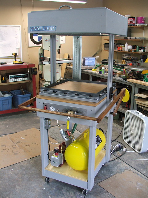
Protoform Vacuum Forming Machine
Quite a bit ago I was able to get my first vacuum forming machine up and running, using not much more than an old toaster oven, a shop vac, and my parents’ old telephone table from their kitchen (with, I should add, their permission to do so!) Anyone interested in that project can take a look at the build log here. Its been a great tool to have and has been very useful for the past few years its been in service.
This budget-miniformer has worked wonderfully considering the cost and time it took to produce, but as I’ve been getting more and more complex projects recently, I’ve been needing a machine capable of pulling larger pieces of plastic as well as thicker and more detailed pulls. I had done a lot of research in the past when planning my mini-former project, and had run across the Protoformer Vacuum Forming machine plans over at Build Stuff more than a couple of times.
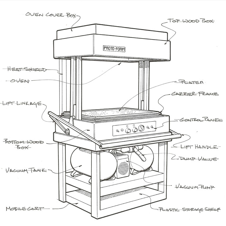
The plans are $65, and worth every penny. I highly suggest anyone interested in making a large professional level machine look into purchasing either these, or some of the other smaller format machine plans available on the Build-Stuff website. The end result (after a lot of effort and a fair bit of cost, its worth mentioning) is a hugely capable and very professional looking tool.
My personal build did not follow these directions exactly; I made modifications to the plans in certain key areas which other people who have built these instructions will recognize right off. These were not improvements, but rather implemented as a result of budget concerns, personal limitations (I don’t have access to welding equipment) and the types of jobs the machine will see. I’ll explain these when they pop up in the project log.
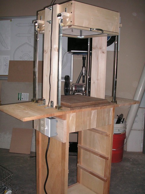
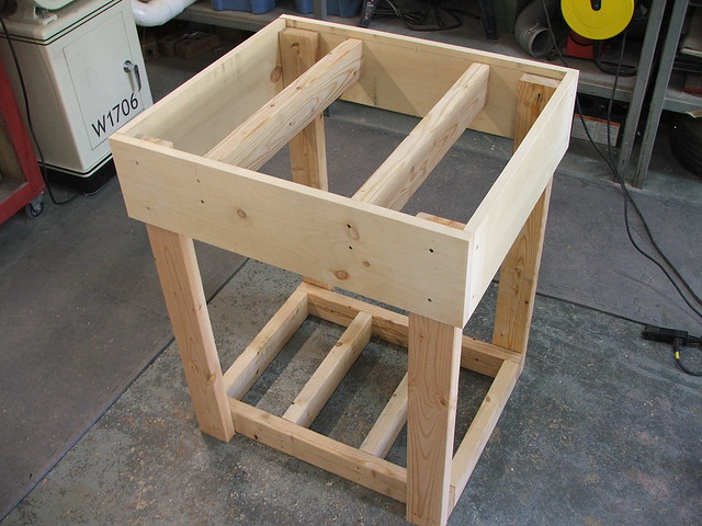
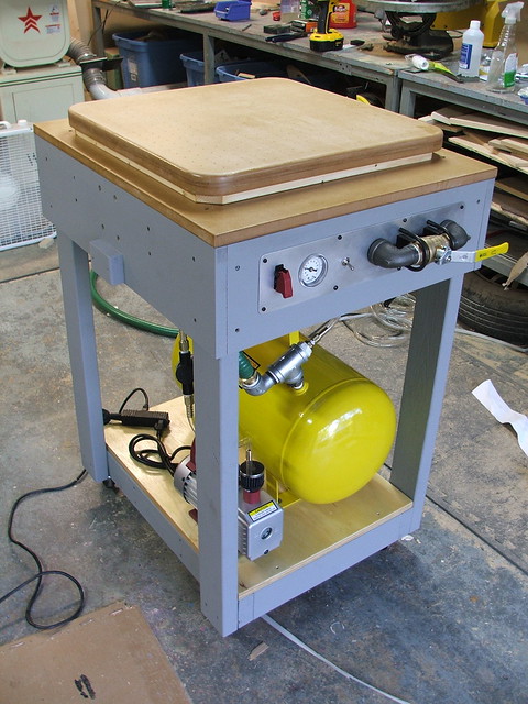
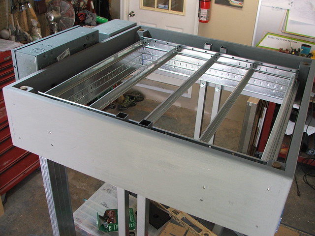
First off, I started by building the frame table. This is a bit smaller than the ones laid out in the instructions as my shop is pretty cramped these days and I needed something with a smaller footprint. Also, I had plans to change the lift rails and oven supports, and I needed a narrower chassis to do so. These are just 2×4 framing studs, glued and screwed together.
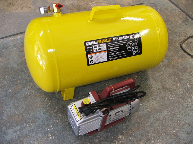
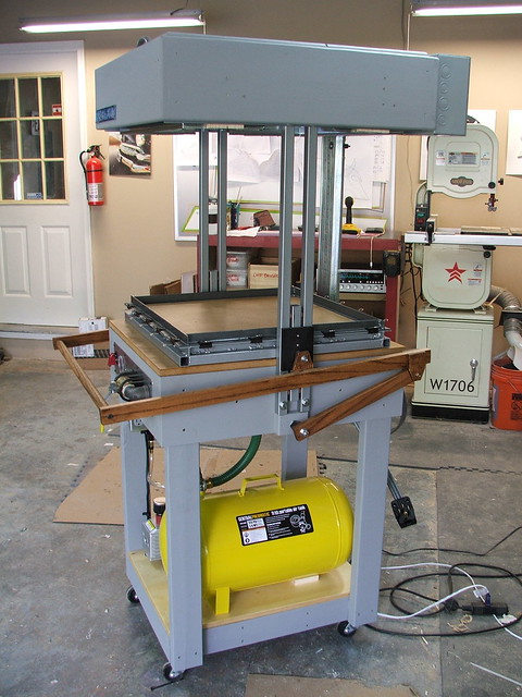
The vacuum itself would be provided by a 3cfm air pump I purchased at Harbor Freight. The 11 gallon surge tank that holds the vacuum was also from HB. To pull thicker materials like Acrylic, I may have to add another tank in the future, but for the styrene and PET plastic I’m working with now, these two will work fine.
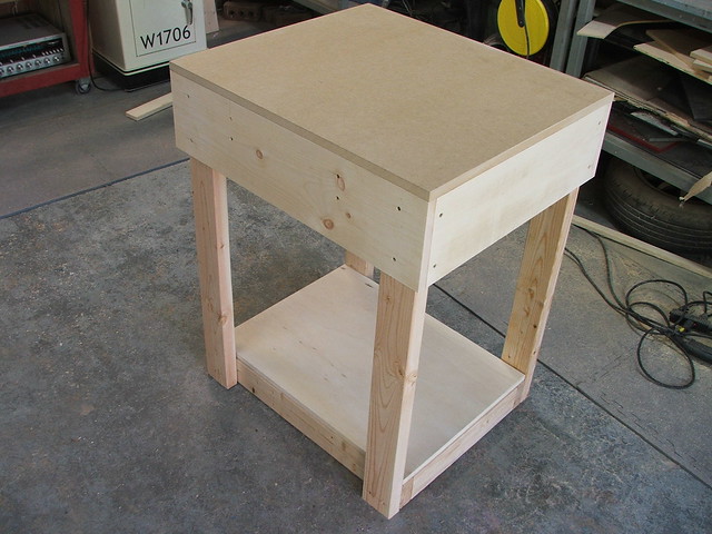
A shelf was added to the bottom of the cart, made from 3/4″ plywood. The upper table area was cut from 1/2″ MDF. Both were sealed with shellac before mounting onto the machine. After mounting points were drilled, the frame was painted with flat gray house paint left over from my laser cutter cabinet project.
The original plans call for the oven support arms to be a set of 4 uprights welded to a steel box that will sit on the chassis. I chose to drill holes through the side of the uprights and bolt them directly to the chassis sides. This saved me some money in box steel as well as saved the complexity and time of cutting parts to length and welding them together. I also substituted 1″ steel box stock for the 1.5″ outlined in the instructions. My machine will see occasional use every few weeks and I didn’t think the added beefy steel was necessary.

The oven frame box was built next. This is a proprietary design and made to specifically hold the heating elements sold by Build-Stuff.com. I chose to leave all the parts of the machine related to the heating and electrical system as close to the instructions as possible.
The outside of the box is made from poplar, and the inside metal grid secures to the outside box with a series of screws.
I used 2 pieces of 1″ angle steel to hold the oven box in place. These are bolted to the uprights and pull double duty; they keep the uprights a set width apart and keep the oven box level and above the platen.
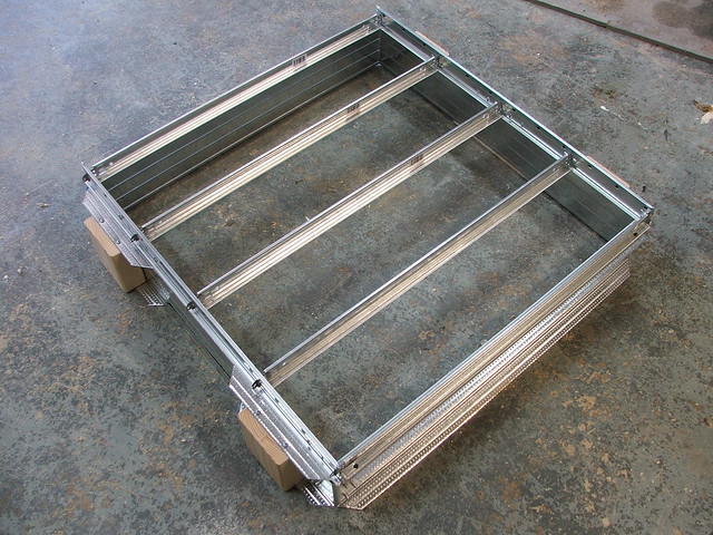
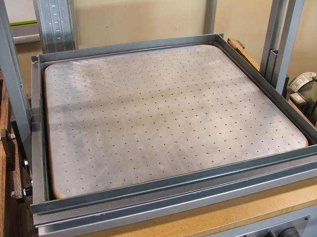
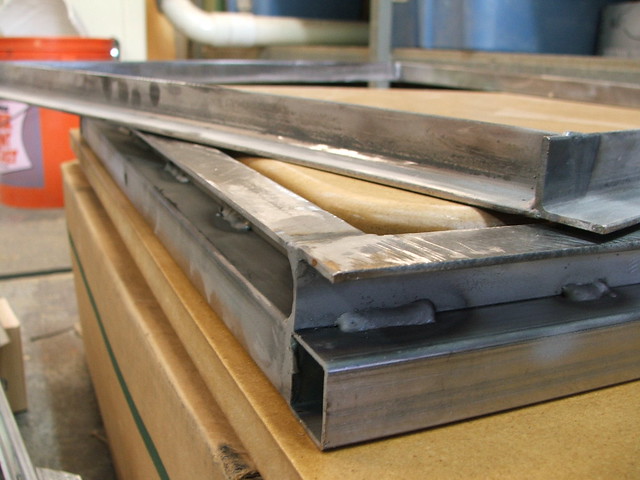
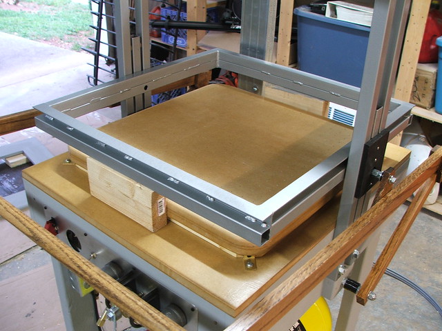
The platen was also modified, though again for budget reasons. I chose to repeat the design from my first vacformer, but incorporate cues from the Protoform design as well. 2 pieces of 1/2″ MDF sandwich a 1/4″ piece to create the inner cavity. A steel mesh frame is mounted in between the open sections to make sure the cavity doesn’t crush inward under the pressure of the vacuum.
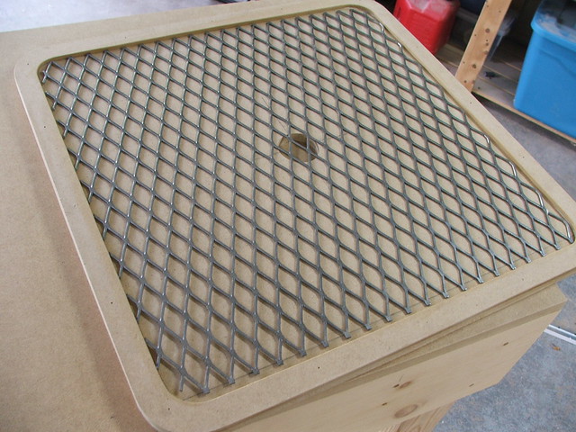
A 1″ threaded PVC insert was cut from the bottom center section and sealed with RTV silicone. The hose from the dump valve to the air tank will mount here later.
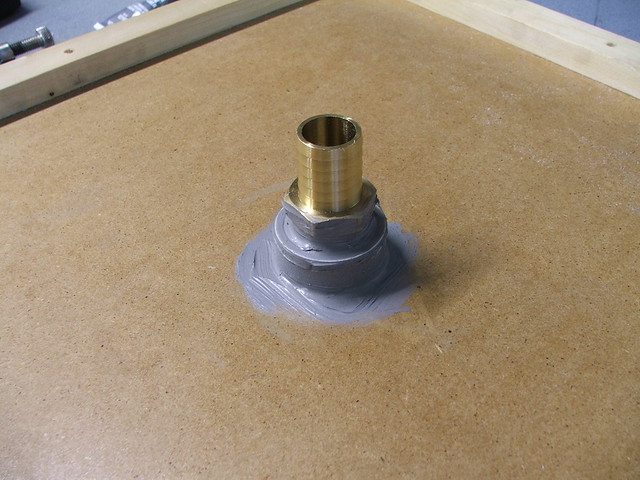
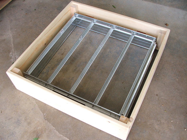
The upper section was routed to have a round corner, then the assembly was glued, clamped, and sealed with shellac.

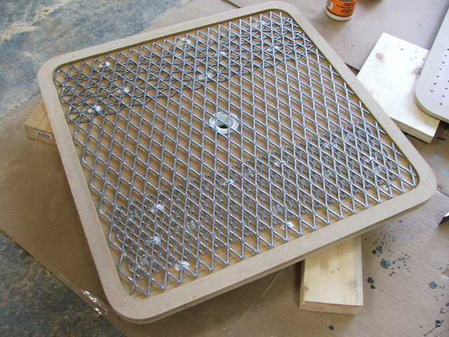
Unfortunately, a test pull once the machine was finished showed that the plastic got hot enough to pull the shellac back out of the wood. I added a thin aluminum plate with matching drill holes, and the problem was solved!

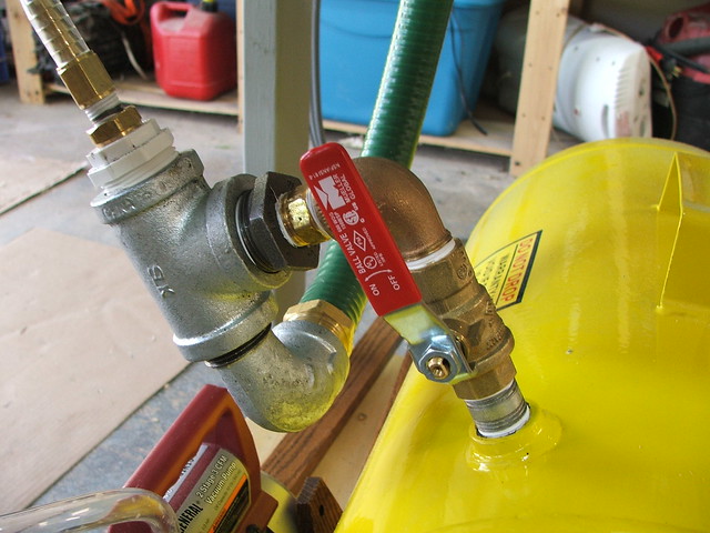
The air system I showed earlier came next. The pump evacuates an air tank, and the amount of vacuum in the tank is shown on the gauge at the front of the machine. When the plastic is lowered to the platen, the valve is opened, allowing vacuum to be pulled though the platen and into the forming area.
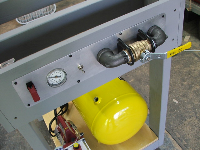
The pump and tank were screwed to the base shelf, then I assembled a menagerie of plumbing fittings and adapters to connect all the parts.
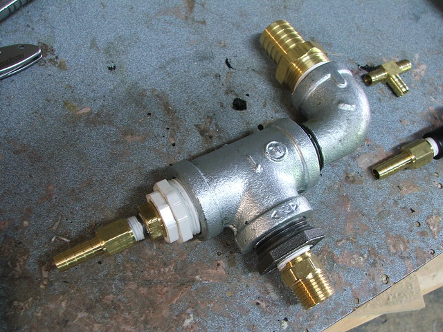
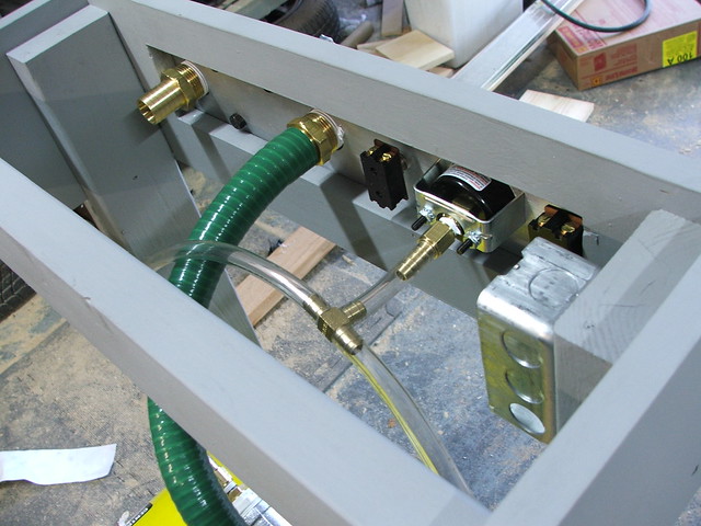
On the front of the machine, there are two switches that control the air pump and heating coils, as well as the vacuum indicator gauge and the vacuum release valve. Mounting points for these were trimmed out of an aluminum plate.
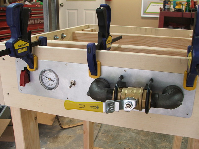
With these parts assembled, I now had the vacuum half of the forming machine finished!
The oven support rails came next, and were bolted to the side of the machine. The oven box was then lifted up and mounted to the angle steel bars.
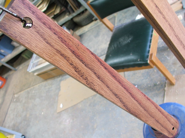
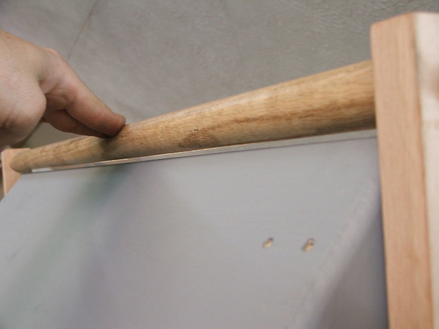
As my dimensions were changed somewhat from the original Protoform plans, the lift arm mechanisms in the instructions would no longer work for my machine. I employed a very similar system as shown in the diagrams, though the lift arms I built are made from red oak.
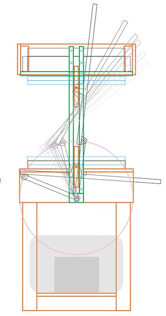
This, again, was a budget and capabilities issue since I don’t own a welder and buying another 8 or so feet of box steel would seriously anger my bank account. The lift arms work quite well, though the wood does flex more than steel would. You need to lift the arms by the sides of the center handle using two hands, whereas I imagine a steel assembly could be lifted using only one.
These lift arms attach to two 10″ long sections of box steel which ride between them. These center rails are then bolted to the plastic carrying frame, which moves the material up to the oven and back down to the platen.

I couldn’t get away from welding forever, so after cutting all of the parts for the plastic carrying frame, I asked my uncle James for a few evenings worth of his free time to weld up the frames for me. James has plenty of fancy welding projects under his belt (race car roll cages being chief among them!) and the results were perfect.
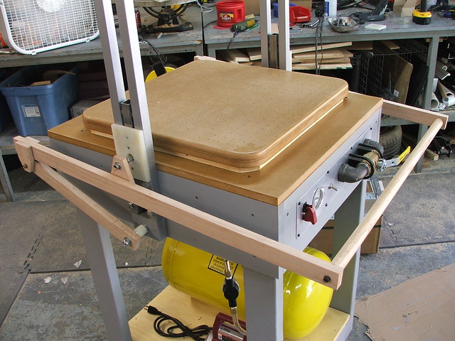
I stained the wood on the lift arms, painted the frames and bolted everything together for a test run. The lift bar clears the oven by the tiniest margin and I have to stand on my toes to reach it, but it works wonderfully!
I’d like to explain the heating elements and electrical wiring in detail, because I try to share as much experience and knowledge as I have for other people to learn from and try out themselves. Unfortunately, this time I’ll need to be a bit more reserved about distributing this information. This machine runs 220V power, is built with its own sub breaker box, and is tied into a 50A breaker in my house.
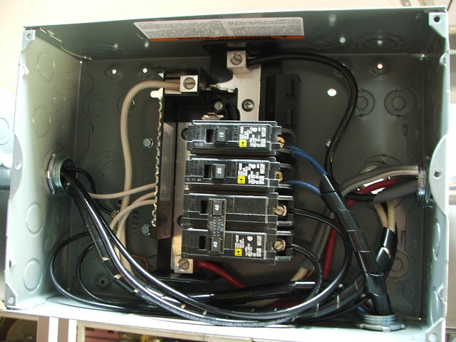
This is easily one of the most dangerous projects I’ve ever constructed, and the simple fact is that if you want to build your own, you should go to Build Stuff and buy the Protoform plans. I should note that at the time I originally bought the plans and wrote this post, I had no affiliation with the company. The instructions are comprehensive, and detailed and far better than what I can summarize here. $65 is a bargain for the amount of information contained in the PDF you get!
My garage used to run off a single 15A 110V breaker, but this has increased exponentially in order to run this one tool. I had an electrician install a new 220V 50A breaker for this machine alone, and also install a new 20A 110V breaker just for the rest of my shop. I can finally turn on the bandsaw without killing my stereo or having to turn off my space heater!
The heating elements are another kit offered by Build-Stuff, and the kits scale depending on what kind of machine you’re building. I ordered these, as there’s no need to reinvent the wheel, and the kits came quickly with clear and precise instructions. Assembling everything took about half a day.
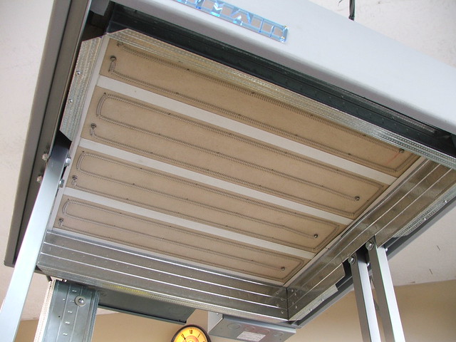
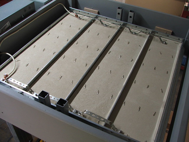
These things get HOT, and in a hurry too. Full working temp is reached in about 2 minutes. The nichrome wire is a bit intimidating to work with at first, but it becomes easier the more you install.
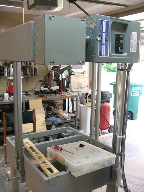
The last thing I needed was a vent cover to protect the heating element wiring from any overhead junk. This was made out of leftover bits of poplar and a large air conditioning vent.

With the oven complete, I just needed to do some test pulls. I’m in the middle of remaking the Mr. Destructoid helmet (another old project from back in 2009) for the guys over at Destructoid.com, and all of the parts will be vacformed plastic. A few of the bucks were finished enough to pull a test piece, shown in the video below.
This new vacformer ran easily 10 times the cost of my first vacformer project, but the results are worth it. I’m actually considering updating the little one with its own pump and vacuum tank in the future to improve its performance as well.

Thanks for reading! More pics of this project (and a bit more explanation of some of the components) are available on my Flickr account.

Skyrim Female Ancient Nord Helmet
Like everyone else who had a passing fancy with gaming, I recently fell very deeply into Bethesda’s most recent Elder Scrolls offering: Skyrim.
For anyone who hasn’t played the game, there’s a wealth of beautiful armor and weaponry. Its the sort of thing where a builder like me wanders around the map saying “I want to make that. And that. And three of those.” The item I found most striking, and the one I chose to build first, was the Ancient Nord Helmet (also called the Draugr helmet.) The write-up below is a pretty brief recount of my build process. If you’re interested in seeing a more complete “step-by-step” account, you can check out the Instructable I wrote here.

If you played a male character in Skyrim, this helmet may seem odd to you; the female variant got these awesome antlers, the men had the ram horns.
I started out with some very nice 3D files ripped from the game, courtesy of a gent who follows my Facebook page and was kind enough to lend a hand with the source imagery.
From these, I made a set of 2D blueprints in Illustrator to pattern the build.

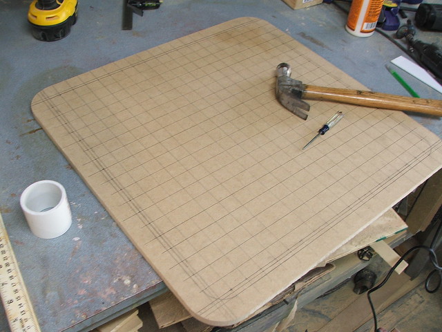
Recently I’ve found a great method scaling blueprints like this to their final dimensions: Print off a 1″ grid onto a sheet of plotter paper, then trim out a space for your subject to stand. Photograph this as close to perpendicular as possible, then import the photograph into an image editor such as Adobe Illustrator. By scaling the image so that the 1″ squares are indeed 1″ in size, you can then import your blueprints over the image and find all the dimensions of your finished part.
The final dimensioned “slices” were cut from 1/4″ MDF and glued together to make a sculpting frame.
Cavities in this frame were filled with polystyrene foam. I used some old water-contaminated casting resin to glue the foam into place, since it can’t be used to make decent casts any longer.

After everything dried, I began shaping the foam with a coping saw, then varying grits of rough sandpaper (50, 100, and 120 mostly) The rough form was then coated in black acrylic paint to seal the foam against the bondo I’ll be using in the next stages.

If this all seems very familiar, that’s because this process is essentially identical to the way my Daft Punk Thomas helmet was sculpted. I’ve not tried this method that often, and I was curious to see if it could be transferred to a helmet like this. It worked great, and I have a few more Skyrim helmets coming up in the coming months which will employ this as well.
After two coats of acrylic, I started building up the shape with some polyester filler. The green goo in these shots is a filler by Evercoat called “RAGE Gold” – It sands much easier than bondo but is also significantly more expensive as a result. A tip for sculpting like this with polyester filler: at a certain point it will no longer be spreadable, but you will still be able to dent it with your fingernail. When it is at this stage, break out your 50 grit sandpaper and start shaping. The lumps disappear easily and you’ve got nice, even shapes.


There was a lot of this shaping, until the final base form was satisfactory.
The end helmet was going to be molded and resin cast, but in parts. The antlers would be molded separately, but I needed a place for them to anchor in the helmet. After carving out a couple of sections in the temples of the helmet, I vacuumformed some acrylic plugs and used these to make smooth even recesses in the helmet for the antlers to mount to.

These were then blended into the helmet with Apoxie Sculpt.

Around the neck of the helmet, there’s a beveled edge that also had a slight gradual curve along the profile. For this, I glued some 1/2″ sintra to the base and shaped it with a dremel. Height measurements were taken every inch along one finished side, then transferred to the uncut side to keep things identical.

After a coat of filler primer and some 220 grit sanding, it was time to start hammering!

Well, okay, not really hammering. The in-game helmet has a pretty drastic hammered finish, but since this piece is thin filler over a foam base, whacking it with a hammer would just result in a lot of cracks and chipped resin. I put a large rounded sanding bit on my dremel and gradually carved out each hammer blow.
Admittedly, I got better at this as I went along. Initially, the upper section of the helmet is a bit too uniform, but I still like the texture. The full process for this took me a little over two days to complete.
After this was done, the entire piece was then sanded with a 100 grit sanding sponge to blend these dents into one another, then the helmet was given another coat of primer.
Raised areas of the helmet around the eye pieces and the large curled filigree on the side were added with thin layers of Apoxie Sculpt. I used the back side of an engraving tool to replicate hammer marks in the surface while the clay was still uncured.
Battle scars were carved into the helmet with a dremel and a rotary wheel, then the large rivets (furniture tacks) were added to the faceplate. The whole part was painted glossy silver and allowed to cure in prep for moldmaking.

The antlers were a real challenge. After doing some research on modeling maquettes and armatures, I started by making a wire base, which was then wrapped in foil and thin sculpting wire. This makes sculpting the final form easier, cheaper, and lighter as well. Getting the initial shapes symmetrical was an exercise in frustration.

With the base form satisfactory, I skimmed the surface in Apoxie Sculpt. The surface was smoothed somewhat, but the nice thing about working with Apoxie is how well you can sand it once its dry. After curing, I smoothed out the entire antler form.


A few more details were added after this smoothing process. I used a dremel with a small ball engraver to carve thin lines along the base and crooks of the antlers, and more Apoxie was added to the antler bases to give them a rough, bony texture.
The molds for this project follow a similar technique to my Daft Punk helmet build, with the only exception being the type of silicone used. The white material in these shots is Mold Max Stroke, and the pink silicone is Mold Max 30. If you’re interested in more detail regarding the moldmaking process, check out this Daft Punk post.
Helmet mold with registration keys
Finished helmet mold
Antler mold with seam line
Antler mold with one half of the mold jacket in place
With the molds finished, the parts were cast. The helmet is cold cast in Smooth Cast’s ONYX resin. Cold casting is a process where you use metal powders mixed with the resin to make the final casting have a metallic effect. With this helmet, aluminum powder was first dusted into the mold, then sifted around to coat all the inside surfaces evenly with a thin layer of powder. I used fine steel wool (000 gauge) to buff the surface to a metallic shine.
The antlers were cast in Smooth Cast 320, because the off-white color of the resin makes for a perfect base color.
After some dremel work and buffing, the assembled helmet took shape!
Neat, but it needed a lot more weathering to look truly “ancient”. I started with dark washes of browns and blacks into the battle scars and crevices on the helmet. Around the rusted areas I used some iron powder, dabbed on with dark purple acrylic paint.
This powder was sprayed with a mixture of hydrogen peroxide and vinegar, then allowed to sit overnight. The results were beautiful rust marks!

Painting the antlers was a bit trickier. I started by shading in the recessed areas with dark brown, then gradually layered thin coats of airbrushed brown on top of this, which were “scratched” away using a stiff bristle brush and warm water over the acrylic paint. The final version, next to an un-weathered helmet, is below.

After sealing the helmet in semi-gloss and the antlers with matte clearcoat, the final piece was assembled and finished!
I’ll have more Skyrim stuff in the coming months, so if you’re a fan of the game keep an eye out. There are many more higher-resolution pictures of the process available on my Flickr page, so take a look there if you’re interested.

Thanks for reading!


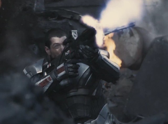
Mass Effect 3 Live Action Commercial
If you’re a fan of the series (like me) and you’ve been drooling over every trailer that’s been coming out recently (like me) you may have seen the latest live action commercial for Mass Effect 3 which aired last weekend. Look closely, and people who follow this blog miiiiight see something familiar:

Yep! That’s one of my N7 Valkyrie rifles, making the first on-screen debut of my props! (okay, technically one of my Portal Guns was in the background of the Sony “Michael” advertisement, but given how long its there for, it hardly counts…)
There’s even been some mumbling over at the Mass Effect facebook page that some of the guns from the shoot may even be given away as special prizes.
I was asked to ship out 4 raw cast rifles to Prague last November for this spot, and I’m just blown away by the results. Muzzle flash! Exploding Geth! Bad Ass N7 Armor! (no idea who made that, but damn its beautiful)

Thanks to the internet and the attention this little blog receives, I get to be part of amazing projects like this. I have no idea how I managed to make crazy stuff like this my fulltime job!
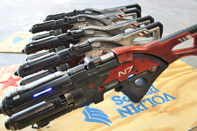
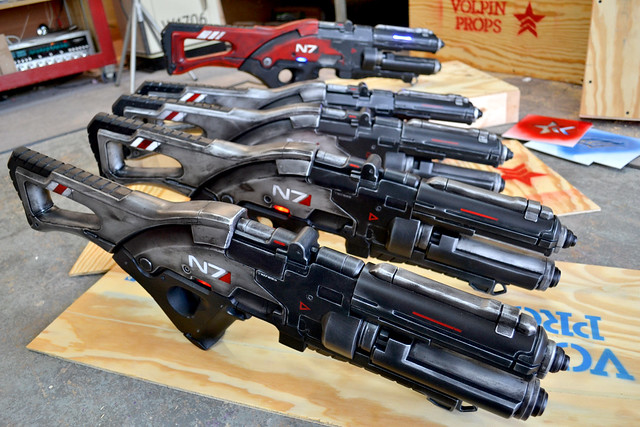
Speaking of Mass Effect 3, I recently re-visited the N7 Valkyrie project for the people over at Bioware. Over the month of February, 4 more Valkyries were produced and are currently awaiting shipping. The red one – that is to say, the canonically incorrect one – is my personal Valk.

Thanks for reading, following, and sharing my work – it’s stuff like that that makes jobs like this possible for me!