
Garuda’s Spine, Final Fantasy 14 (part 1)
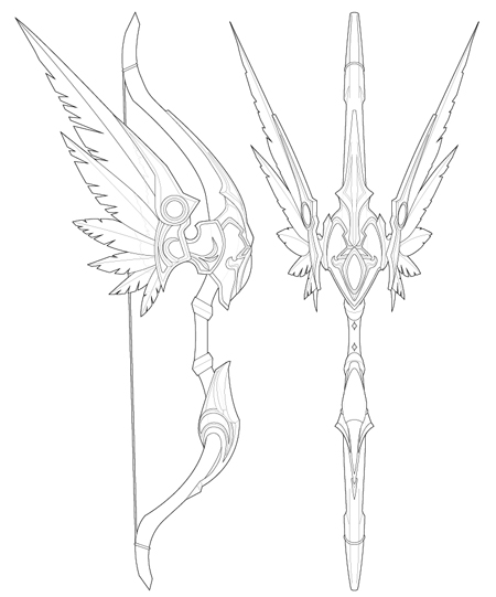
In terms of scale, Garuda’s Spine is the largest prop I’ve built to date. The weapon itself is everything that epitomizes the world of JRPG excess: a seven-foot tall bow fitted with a shield crest and 40″ long fold out wings. The finished piece was intended for use with cosplay, and therefore had to be built as lightweight as possible. My client gave me the luxury of an extended timeframe, and I really buried myself in the details of this piece. I wanted it to be perfect, with a degree of finish that some might consider unhealthy. This was going to be my best work yet.

Starting off, I made the bow 85% scale to true game size. Even for a 5′ tall client, the bow would be nearly 7’4″ in overall height and the massive wingspan wouldn’t fit through doors. At 6’5″ the bow is still imposing but far more manageable. The first step was to make a set of blueprints to reference during production. I pulled a lot of screenshots both from the game itself as well as the FFXIV model viewer.
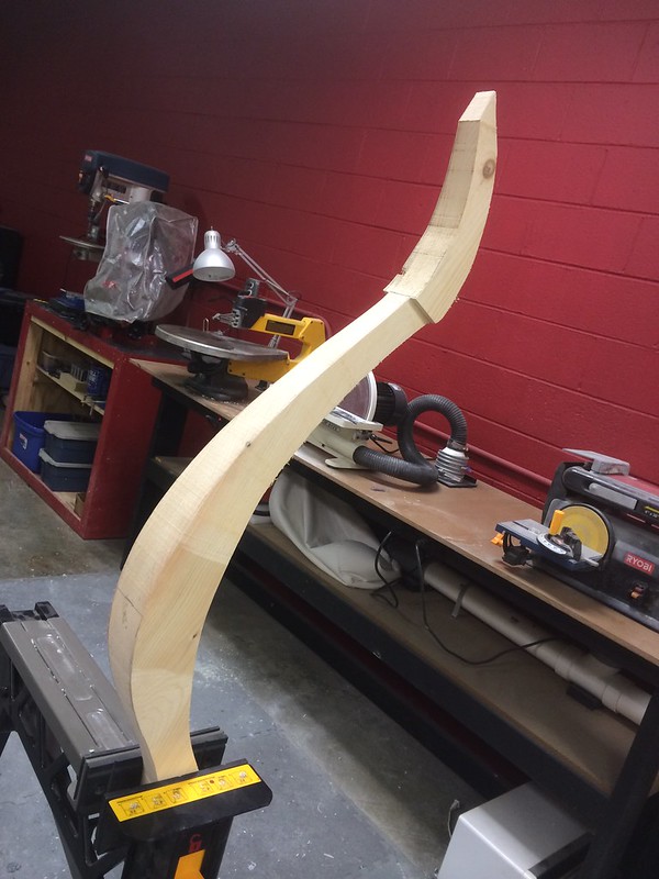
The massive limbs would be upwards of 4″ thick in some places, and needed a very large piece of stock to sculpt from. I laminated several sheets of 1″ poplar together to create a giant slab, then rough cut the bow limb shapes out on my bandsaw.


These were then trimmed down to shape using an air grinder and a chisel drum bit to remove large chunks of material. I swapped this out for a sanding drum, then eventually hand rasps and sandpaper.


The interior of the bow limbs didn’t have much detail in-game, so I added a recessed channel along the back side to keep the shape from looking too flat. At the same time, the handle between the limbs was turned from a scrap block of laminated poplar.


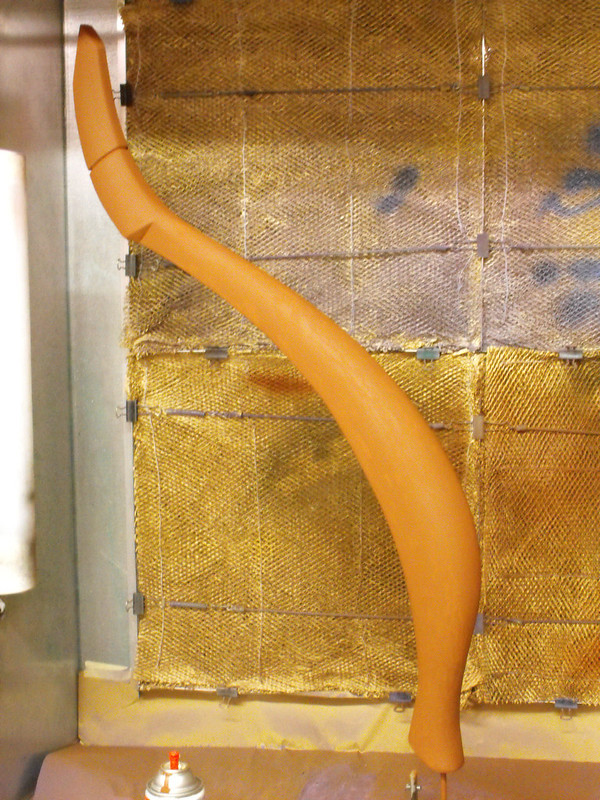
With the shapes complete, urethane resin was brushed over the wood to seal it in prep for sanding and paint. This plastic coating ensured the wood wouldn’t swell or crack during the painting and moldmaking process to come.

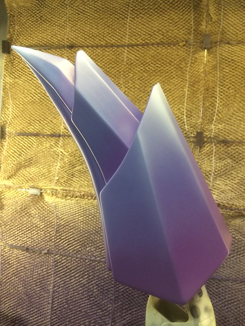
Scale on these things is somewhat lost in the photography, so here’s just the upper limb in my spray booth. The overall interior dimension of my booth is 4′ square, and this is just one half of the bow. It barely fit.
After beveling the handle on the top and bottom, it was secured to the limbs with a wooden dowel. The intersections were built up with apoxie sculpt into the beveled rings seen below.

I’m posting the progress on this slightly out of order to follow the build path of each individual component. Chronologically, the upper and lower crests for the bow had been sculpted and cast at this point, and I used those castings to create a set of standoff blocks fitted to the bow limbs that would properly hold the crests in place.

Making the limbs one piece meant the bow could no longer fit in my spray booth, and the remainder of the paint work was completed with the limbs balanced on a pair of jack stands off the end of my loading dock.

First passes of primer revealed some areas that needed filler and sanding to get properly smooth.

After a lot of sanding, the primer coat was ready for paint. Last stage of prep involved sanding the entire bow surface with a super fine sanding sponge then cleaning the surface with wax and grease remover.

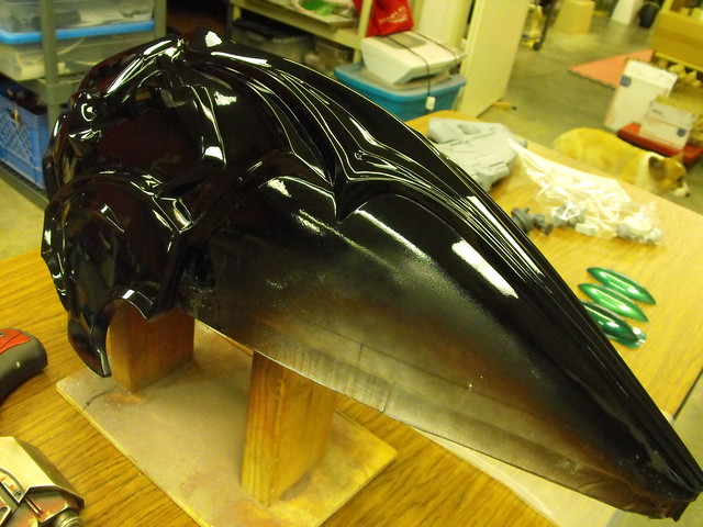
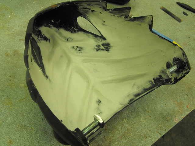
In order to spot surface variations more easily the limbs were painted with gloss black. Since I had to wait 24 hours for one side of the bow to dry before I could flip it over and paint the opposite side, this process took a while.

Painting in multiple stages like that meant the finished product had some lumpy over spray in some parts, which meant it was time for wet sanding. Wooooooooo. I started with 600 grit and eventually worked through 1000, 1500 and 2000 grit before rubbing compound and wax.

The finished result was very sleek.

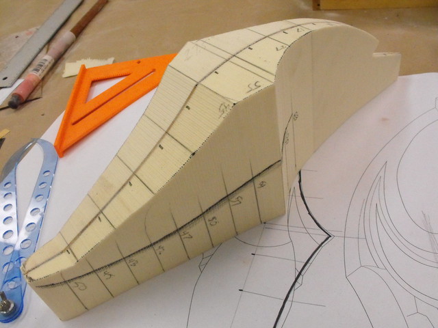
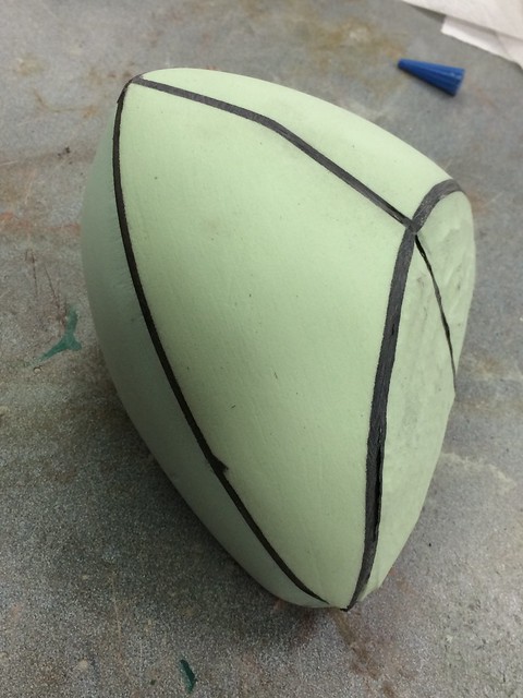
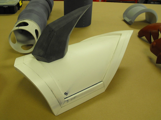
For the upper crest, I went back to my “3D slice and foam filled cavity” method of sculpting employed on many of my helmet projects. The base form is an internal skeleton made up of cross sections of the overall shape. The space between is filled with urethane tooling foam, then sanded down to shape using the internal frames as sculpting guides.


I use a rasp and heavy grit sandpaper to get the base shape complete. For this part I also added some reference lines so I could measure the curve with a contour gauge and make sure both parts were symmetrical.

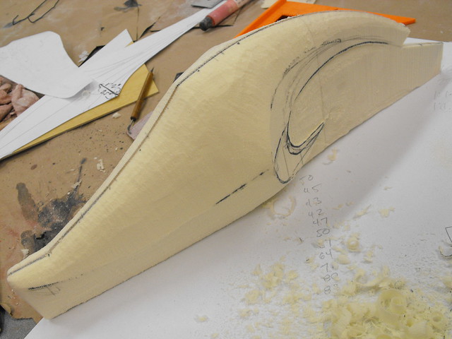
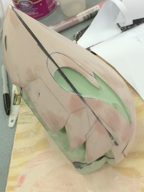
The foam is very fragile on its own, so I tossed the whole part under my vacuum former in order to give it a more robust shell for sculpting and paint.


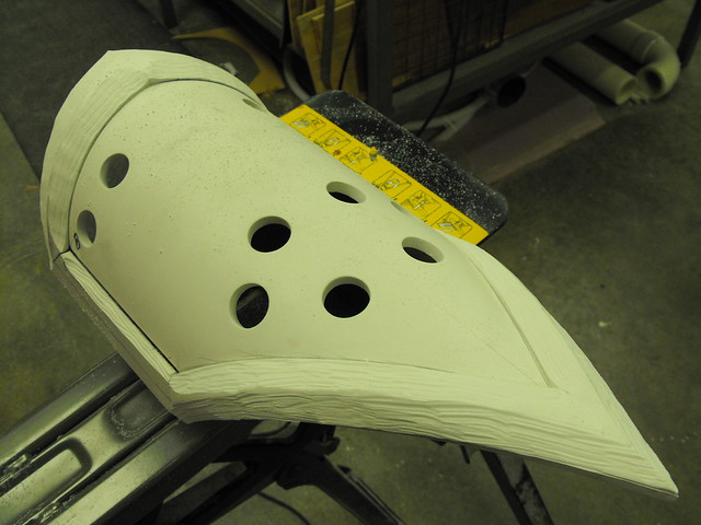
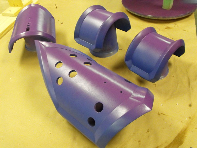
After filling in some low parts with bondo, the filigree pattern on the upper crest was transferred from the blueprints to the 3D form using a compass, calipers and curved ruler. This. Took. Forever. Also added at this point were the two smaller “wing holders” that would eventually mount to the gold base parts holding the feathers on either side of the bow.


I took my time sculpting the filigree parts, making sure each section was symmetrical and cured before moving on to a new part. Mostly these were done in Apoxie Sculpt but I also tried out Smooth-On’s Free Form Sculpt in a few areas. If you’re interested in the contrast between the two materials you can see my comparison on them right here.


As with everything, much sanding was needed to get my rough sculpts perfectly smooth. Apoxie sands very well but it’s also incredibly dense, so this also took forever. I spent lots of time with needle files making sure each recessed angle was crisp and even.


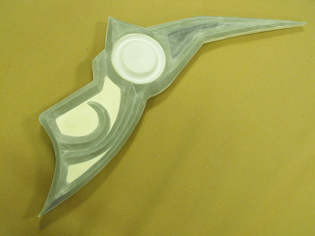
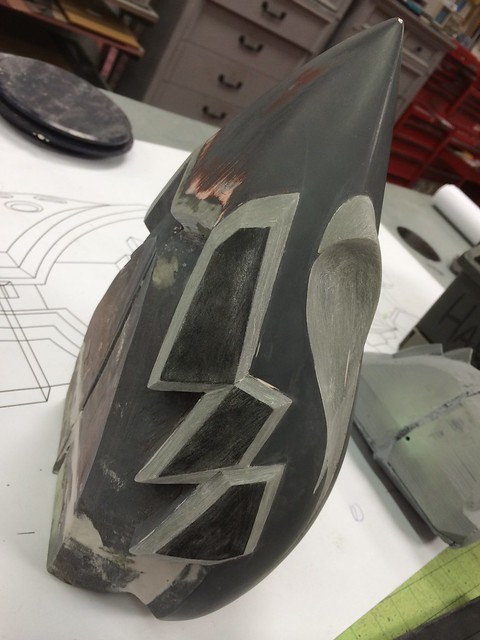
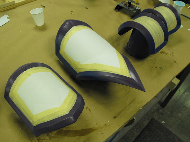
Sanding and filling complete, the upper crest was painted in gloss black and was now ready for moldmaking!

Sculpting the lower crest followed a similar pattern – cross section with urethane foam first. I used bladed clay sculpting hoops to get the recessed areas a bit more crisp on this particular piece.

This was then vacuum formed under white styrene for rigidity before tracing the filigree pattern onto the surface.

Filigree to epoxy clay, then sanding…


…then primer, then shiny black. Starting to see a trend here!

The feather holders for the wings are vertically symmetrical so I only needed to sculpt and mold one version which could be used for both sides. Sintra sheeting was used for the base internal form and to give the part it’s needed thickness.

A vacuum formed foam puck created the round centerpiece for both sides of the feather mount… then, more Apoxie Sculpt (I swear I’m not sponsored by Aves) for the filigree.


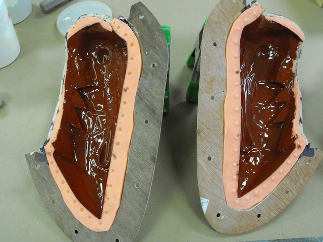
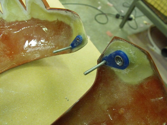
…followed by copious amounts of sanding prior to a coat of gloss black in prep for molding (shown here embedded halfway into the matrix molds which I’ll cover in part 2)


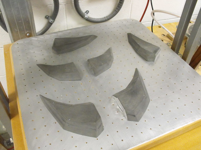
The last component were the enormous feathers that make up both wings. The smallest one is 6″ long and the largest is over 30″ from tip to base. Each feather was individually trimmed out of a sheet of 3/4″ MDF. I needed to do this twice as the feathers are mirrored, not symmetrical.

Each form was then beveled on my belt sander to create a peak. This would give the eventual vacuum formed copy added rigidity but also make the cast parts look more visually interesting as well.


Beveled cuts in the feather bucks were added with a scroll saw to simulate the chunky breaks in the feathers represented in the game. The beveled edge makes sure the forms are easily removed from the styrene after vac forming.

One sheet nets one wing, then each set was trimmed out and layered according to the order of the feathers in the game render.


Here are the two sets after glue and assembly. These aren’t affixed to the cast wing holders quite yet.

That’s it for the mold masters! This is an insanely abbreviated version of the work that went into making these forms ready for silicone, but I get the feeling people won’t sit through the novel that this project would need in order to explain every step fully. If you’re after more information and detail, be sure to check out my Flickr page about the project right here.

The upcoming part 2 will cover mold making, paint and assembly. Be prepared, that entry will probably be longer than this one.

Thanks for reading!
All of the products listed in this write up are the products that I used and can recommend. Some of them are provided as Amazon affiliate links, which help support Volpin Props.

Cael Hammer, Bastion
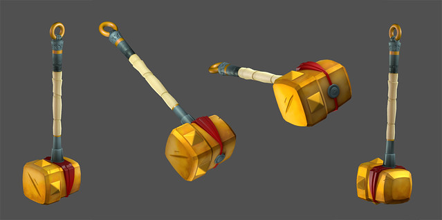
I was very giddy on the day I got an email from the Art Director at Supergiant Games. Both Bastion and Transistor are personal favorites of mine and I jumped at the chance to be able to make something for this studio. They needed a copy of the Cael Hammer, a weapon wielded by The Kid from the very onset of the game Bastion. Since the game takes place in 3rd person isomorphic perspective, new higher-definition renders were created for me to use as a reference.
The hammer itself would be used alongside a green screen for attendees at PAX East to pose in the world of Caelondia. The finished piece needed to be very lightweight but also durable, and blend into the high contrast illustration that would make up the background. EVA foam seemed to be the best solution. I sourced some 4×8 foot sheets in 0.5″, 1″ and 2″ from foambymail.com and set to work. This was way more than I needed, but no problem with stocking up in advance.
This is only my second foam build, and I’d like to take a minute to thank people like Evil Ted Smith and Punished Props for their detailed tutorials on working with EVA foam. Ted has a great series of YouTube videos here, and Bill Doran’s books on working with EVA foam can be purchased in my online store.
Most of the hammer was free handed based on a set of illustrations I made off the new render. Larger areas like the face were cut from thicker 1″ material, while the sides of the head were cut from 0.5″ material. I used barge cement to glue all parts together.


The super thick 2″ foam came in really handy for the side spikes as well as the large back side of the hammer head. Cutting tapered forms out of thick material means slightly more weight, but also less seams that need blending. Spikes were trimmed on my bandsaw by setting the work table at an angle and cutting each face individually. The large back section was shaped by hand on a belt sander.


Thinner 6mm and 2mm foam sheets were used to make the red band across the mid section of the head. For all the thinner foam parts I used an exacto knife for cutting.


Several parts needed to be made a bit more robust than EVA foam. The pommel would contact the ground a lot, and a few bits on the hammer head would be easier to construct from rigid plastic. Since they still needed to be lightweight, these pieces were vacuum formed out of .060″ styrene sheet. I started with the pommel, turning a forming buck out of urethane foam.

Parts for the neck and top cap were also turned from urethane foam, as well as the large donut half that would make up the bottom part of the pommel.


Before trimming, the pommel halves were glued together using methacrylate to make full continuous parts. Once the glue dried the seam lines were sanded off.


The pommel has some Caelondian writing in two different sized rings. These were first trimmed out of vinyl then laid over the plastic to act as a guide. The engraving was done by hand with a rotary tool and ball engraving bit.


With the base sculpting done the two parts were glued together using a steel bar between them for rigidity. Apoxie Sculpt was used to make the ornamental band that secures the ring to the rest of the pommel.


Other styrene parts taking shape: the top cap for the hammer head and the lower hammer neck. Both parts seat into a thin score line cut into the foam to better hide seams between the disparate materials.


To add rigidity to the head, a section of PVC pipe runs from the top cap through the bottom and ends in a threaded nut. This connects to the other PVC section that forms the handle.


More EVA foam was used to simulate the handle wrap. To get the tapered look, material was sanded off the back of the foam to make it thinner before gluing it down to the PVC pipe. By sanding the back side, the smooth surface of the foam is kept intact and greatly reduces cleanup later on.

With all the parts complete it was time for paint! There’s a lot of different schools of thought when it comes to painting EVA foam, but my techniques are based largely on the work of Evil Ted Smith and Punished Props, with a bit of my own invention here and there.
Firstly, I needed a way to hide and blend a bunch of the seam lines between the foam panels. I found a tube of thick acrylic paint called Gallery Glass that’s normally sold in craft stores as a way to fake stained glass leading. Since it’s made to dry even when applied in very thick coats, this stuff worked wonders at filling in seams. It’s even flexible! In the shot below, all the black smears are Gallery Glass filling in the seam lines.

After letting the filler cure overnight, I sealed the foam with white Plasti-Dip. I decided on white since it would be easier to see even coverage over the predominently black panels used on the hammer construction. It took about 7 thin passes to get a fully sealed, opaque coat.


This was given another 48 hours to dry before priming with 2K Urethane Primer. I added a bit of flex agent to this coat to allow it some give with the foam and Plasti-Dip. The nice thing about a high build primer is it can be sanded back down to make a very smooth surface. A few passes with 320 grit sandpaper and the rough pebbly texture of the Plasti-Dip was much smoother.

In this photo you can really see the rough texture left behind by the Plasti-Dip. I’d gotten about half of this side of the hammer sanded at this point. The urethane fills in these divots and sanding makes everything nice and smooth.

For paint, I started off base coating the entire piece with Createx Wicked Colors white. A white base coat means the yellow topcoat will be more vibrant and even.


To emulate the painted vibrant style of Bastion, many passes of darker airbrush yellow shades were added to accent the edges and corners of the hammer head.


The band was masked off and painted red, with its own gradients and shading. Wicked Colors are great because they don’t require an intercoat clear for masking off layers once the paint is cured.

Lastly, the spikes were tipped in lighter yellow and darker orange blotches were added in the corners with an organic sponge.

Yellow sections of the pommel were painted in the same process as the hammer head before being masked off to add the marbled blue elements. With the yellow behind a protective layer of Tamiya tape, the pommel was basecoated with more Wicked Colors in bright blue. The yellow was painted first because covering blue with yellow would be nearly impossible.


Marbling was added with darker blue by moving an airbrush across the surface of the part quickly and randomly. This is a pretty common technique for SFX artists doing creature work when they’re adding mottling layers to skin.


This effect is pretty stark on its own, so it was softened with another gradient pass of lighter blue.


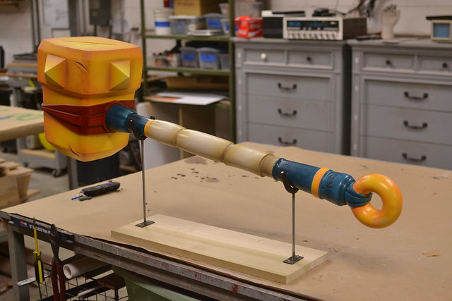
With the tape removed, here’s the finished parts!


The handle was painted in a similar manner with gradient passes over seams and raised areas. Unfortunately I was in a bit of a build zone when I got to this part and skipped on photographing a lot of the paint process. Whoops! Each component got a coat of flat urethane clear before assembly.

I also put together a small display base out of a sheet of poplar and some welded steel bars. I love having a welder in the shop!

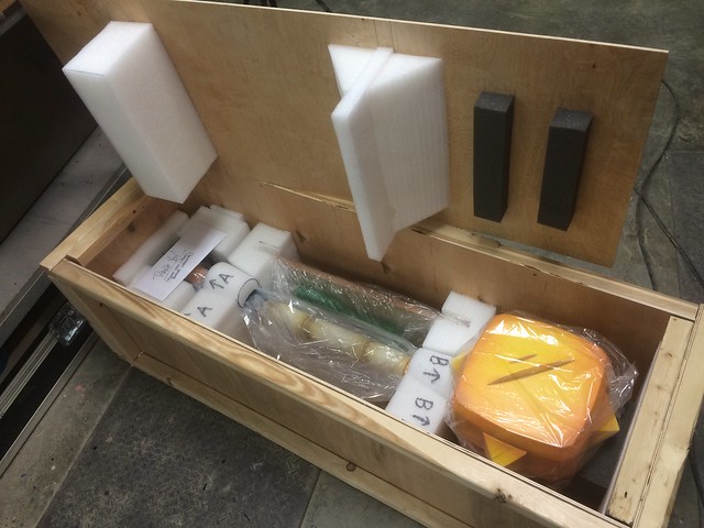
The last component was a massive shipping crate to get the hammer safely to Boston for PAX East. Shipping a 4lb hammer required a 35lb box. It arrived in perfect shape!

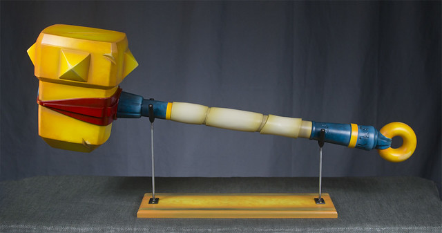
Here are some shots of the finished product. The hammer is about 44″ long but weighs less than 4lbs! You can see them in higher resolution in the portfolio section.

If you’re interested in seeing more progress shots, head over to my Flickr – it’s updated every time I get work done at the shop so there’s always something new to check out.


Thanks for reading!
All of the products listed in this write up are the products that I used and can recommend. Some of them are provided as Amazon affiliate links, which help support Volpin Props.

Curse Gaming Awards, (part 2)
For part 1 of this project, click here.
At the end of part 1, the main sculpt of the dragon was finished, clearcoated and ready for molding. The finished castings would need to be pressure cast in order to make them completely clear, so the mold itself would have to be constructed in a very specific manner.

Pressure casting involves taking a mold and placing it into a large sealed chamber specifically meant to be pressurized. After resin is poured into the mold cavity, the chamber is sealed and pressurized to around 55-60psi. Since gasses can be compressed but liquids cannot, pressurizing liquid resin causes all voids, bubbles and air pockets to collapse and leaves the casting free of any trapped air.

This means that the silicone mold itself must also be free of any trapped air, since small bubbles in the mold will be affected by pressure and will deform the mold surface. The short version of this is that the dragon would have to be matrix molded.
In matrix molding, the mold jacket is made first then the master sculpt is placed into this shell and the void between the sculpt and jacket is filled with silicone. This allows the mold material to be vacuum degassed, removing any air pockets and leaving only the liquid rubber material.
First, the mold master is wrapped in plastic then sculpted over with clay that represents the final shape of the silicone material. Water clay works best, though try to avoid WED clay as it’s more difficult to sculpt rapidly into shape.

You can see I’ve also sculpted in registration keys as well as the parting seam line along the head crest of the dragon. It’s a good idea to take a plastic toothpick and check the depth of your clay from the master sculpt, to make sure there aren’t any thin spots.
Parting seams are added in, using aluminum roofing flashing panels pressed into the clay. The sections where these panels overlap are stuck together temporarily with aluminum ducting tape.

After the clay and parting seams are added, the entire piece is clearcoated with acrylic spray clear then waxed with sonite. This seal makes it easier to clean the clay out of the inside of your mold jacket once complete.

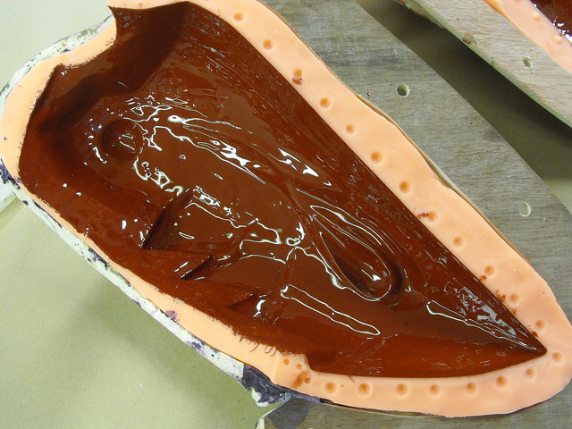
The process of adding a jacket is similar to a brush on mold. For this piece I started with EpoxaCoat Red as a surface print coat layer to capture all of the detail of the clay. Epoxy is great to work with here as it has a long working life but won’t run off vertical surfaces.

In order to make the mold jacket completely rigid, EpoxaMite 102 was layered over with glass fiber cloth to build up a thickness of about 1/8″. Three layers of glass cloth on the main body and four along the seam lines ensure nothing slips out of place.

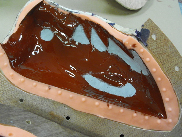
After letting the epoxy dry overnight, the seam lines are cut smooth and sanded to remove any sharp edges. Holes are also drilled in seam flanges so the jacket can be bolted back together later.

Here’s the finished jacket after cleaning out the water clay. In order to keep the jacket from locking into the silicone it was split into five sections. There are a lot of undercuts to this sculpt that necessitate a fairly complex set of seams.

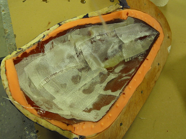
In order to make a parting seam for the silicone, the master sculpt was embedded into clay in one half of the mold jacket. Registration keys and lines were sculpted into the clay before the jacket was re-assembled fully.

I used Mold Star 30 for this mold – it’s a very thin silicone that degasses easily and works great for matrix molds due to its low viscosity. This is one half of the mold after curing and removing the previously clayed-up side shown in the step above.

Here’s the finished silicone mold with the mold jacket removed. You can see how this parallels the water clay sculpt I made earlier.

And here’s the beauty all opened up! I’m quite proud of this mold, definitely one of the better ones I’ve built over the years.

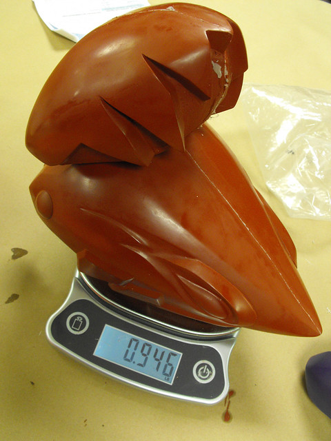
This mold was then plunked into my massive pressure casting chamber to pull copies of the dragons. Each casting takes 96oz of Smooth Cast 326 (a slower setting version of SmoothCast 325, which allows me to fill the mold and pressurize the tank without the resin curing mid-process.) I split this into two pours – one half is 48oz of resin tinted orange and the other is 48oz tinted yellow. By alternating the pouring of the resin batches I can control a bit of gradient shift in the finished castings.
The castings come out very smooth and clear, but the surface has a bit of orangepeel on it from the mold release used during the casting process.

This is sanded off and the whole casting is wet-sanded to 400 grit to even out the surface and remove any visible seam lines.

Each casting is then sprayed with three coats of gloss urethane clearcoat to get things nice and shiny. This whole process takes a while, but the results are worth it.

I also made a large disc casting to serve as the base. Nothing too fancy, just a simple block mold which was cast in black tinted 326 resin then gloss clearcoated. Castings are secured to the bases with two acrylic rods and some thickened epoxy resin to keep things in place.

All told I made nineteen copies of the Curse dragon as awards for employees who had been with the company for five years or more. Later on this year I’ll be sorting out their ten year awards, so check back later to see what happens!

Here’s a few shots of the finished castings. They’re about 14″ tall and weigh around 9lbs per piece.


If you’re interested in seeing more progress photos, you can always check out my flickr for bigger photos and more detailed descriptions.

Thanks for reading, and check out higher res shots of the finished product in my portfolio!

Curse Gaming Awards (part 1)
Curse Gaming approached me in late 2014 with a project: an award for employees who have been working for the company for 5 years or more. The idea was that a 3D clear representation of their dragon logo would be sculpted, molded, cast and mounted to a base. It needed to be something imposing too; large and heavy was a necessity. The flat vector dragon logo looks like this:

I’m less of a designer and more of a replica artist, so I brought my friend Tom (who happens to also be one of the lead animators on the TV series Archer) in on the project to draft up some concepts. Since this part was going to be a resin casting, there were some restrictions on the type of shapes the sculpt could take on. Long spindly bits had to be blunted and down-turned spikes that would trap air and bubbles were streamlined into the profile of the design to make the casting process easier.


With the concept sorted, I started the sculpt. Two big chunks of 5lb urethane tooling foam were glued together and shaved down. Initial cuts were done with a Ryoba (woodworkers will cringe at this but these saws are fantastic on foam), followed by a hand rasp and some large sculpting hoops.


When the shape began to need more finesse, I switched to smaller sculpting hoops and 80 grit sandpaper for shaping. This…swan thing was the resulting form.


The foam swan was painted with a coating of Smooth-On’s EpoxAcoat Red to give the fragile urethane a dense covering that could be sanded to finer detail as well as sculpted onto.

Some of the flame shapes were added at this point with Apoxie sculpt. I also shored up a bit of the lower jaw area with some Apoxie to give the next steps more surface area.

Typically I don’t work with oil clay but it’s definitely a material in which I’ve wanted to develop more familiarity. I knew that I couldn’t get the head of the dragon to the shape I wanted with rapidly curing clay like Apoxie, which has about a 45-minute to one hour working time before hardening. By sculpting the head out of oil clay (in this case, Chavant NSP Medium) I could re-work the shape and take my time as it developed.

Rough forms took shape by adding small balls of clay to the neck and smoothing them into place. I built up the lower jaw, cheeks and head spikes first.

A couple wooden balls were placed into the form to serve as eyes, and this allowed me to add eyebrows and refine the under chin area a bit more.

To smooth out the sculpt I used oil and wax remover. This is a wipe-on material used before clearcoating painted parts to remove any surface contamination. It also does a good job of softening the surface of clay to allow a sculpt to be smoothed out with stiff bristle brushes.


When I was satisfied with the head sculpt, I lopped off the clay upper section with the Ryoba.

That might seem weird, but no matter how much I finessed the clay I was never doing to get it as smooth as the sanded hard parts at the bottom of the sculpt. The clay head was affixed to a wooden box and I poured in some Mold Max 30 to make a waste mold.


A waste mold is essentially a throw-away mold and won’t produce great results. In this case the two halves were made by cutting a seam line by hand with an exacto knife. This isn’t as precise as a properly set up 2-part mold, but I only needed one copy and it works well enough for the short term.

Here’s the head straight out of the mold. The white resin really lets you see all the pits and divots of the clay sculpt.

After a bunch of sanding the dragon head looks a lot smoother and now matches the base.


The head was re-capitated and the seam blended to hide the surgery. For priming this piece I used urethane 2K primer applied with my HVLP gun. The higher build and shorter cure time allowed me to work faster and hide sanding marks more easily.


After final wet sanding the finished dragon sculpt was painted gloss black then clearcoated for maximum shine before molding.

That wraps part 1 – part two will cover moldmaking, casting and final clearcoat!


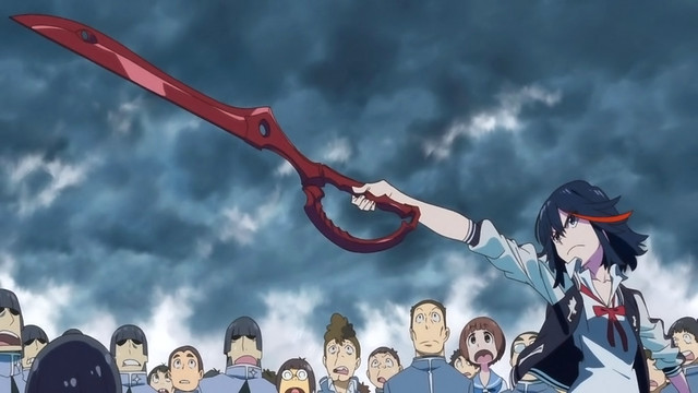
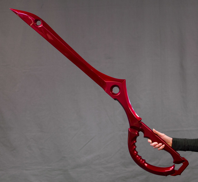
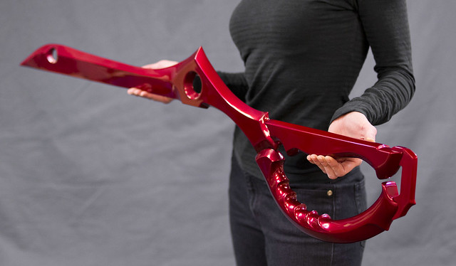
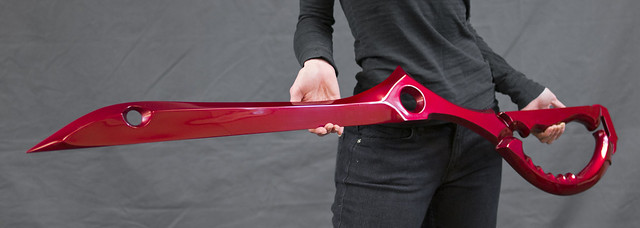
Scissor Blade, Kill la Kill
You gotta love anime. If nothing else, it’s creative. The Scissor Blade is one half of an enormous pair of scissors, used like a sword by the main protagonist of Kill la Kill to wage war against sentient clothing in order to avenge the murder of her father. It’s also bright red and very cool looking. I had to build one.
I started off with some 2D blueprints, using references from the show concept illustrations as a guide for scale. These were also used as references for the overall shape, as hand drawn animation varies wildly from frame to frame.
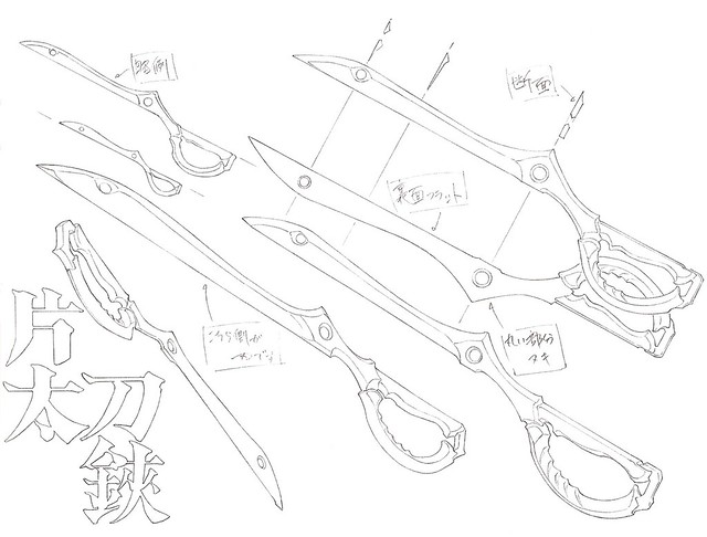
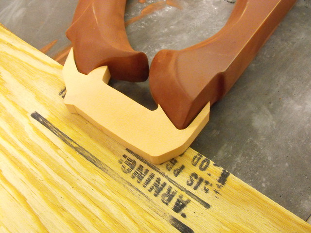
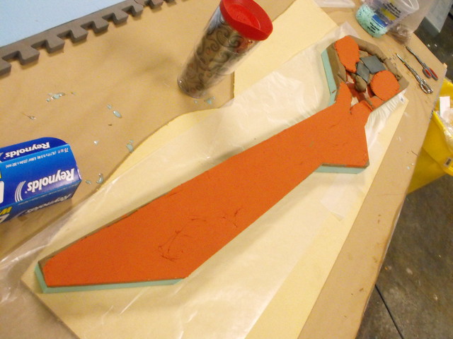
1/4″ MDF made up the main blade portion, with some 3/8″ pieces cut out for the handle sections.
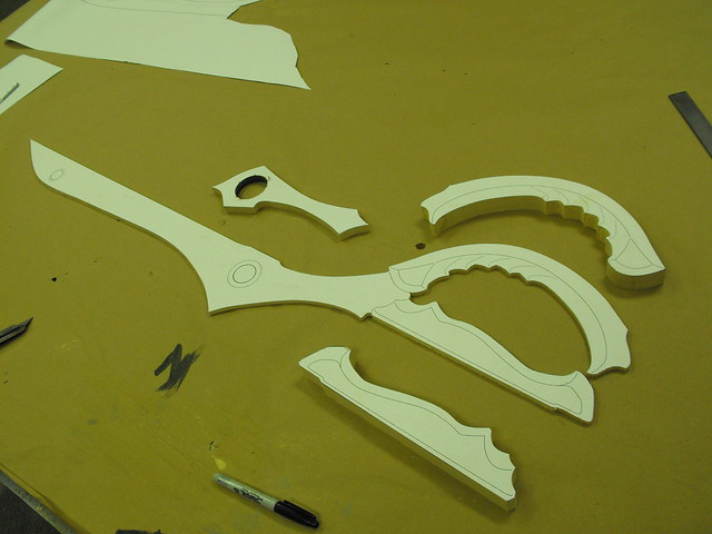
Edges were trimmed with a rotary tool and belt sander, then refined by hand sanding.
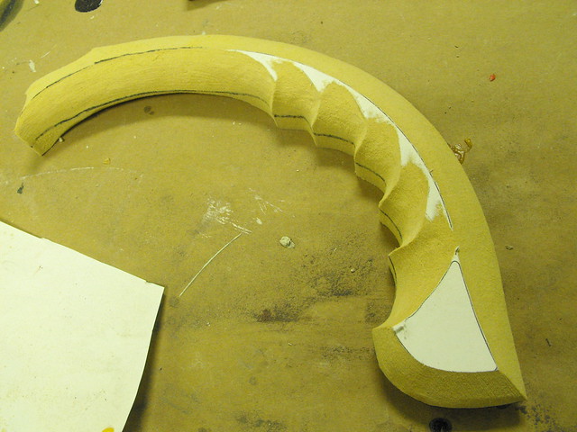
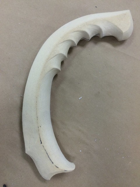
I temporarily stuck the halves of the handles together with double sided tape so the profiles would be identical during shaping. After this was finished, they were split in half and glued to the 1/4″ sword center section.
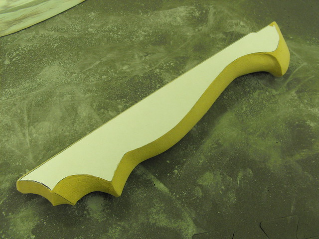
In order to keep the blade stiff, I glued a 1/4″ steel bar onto the thin MDF. This was then beveled into shape with apoxie sculpt.

The blade is very thin, and unlike a sword it’s completely flat on one side. Scissors have to be sharpened this way in order to cut material. I decided to keep this sculpt true to that fact (which is also how they drew it in the anime, but they almost never show the back side since it’s very boring and flat!) Making MDF this thin turns it into a crumbly mess, so I painted the blade portion with urethane resin to give it added density.
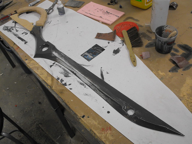
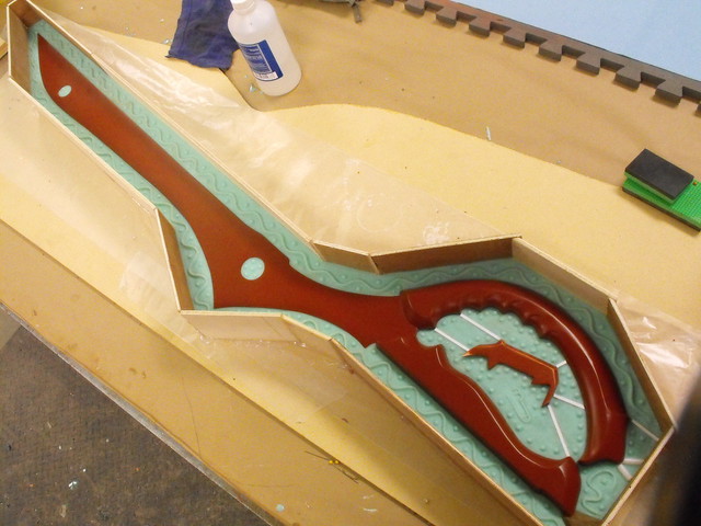
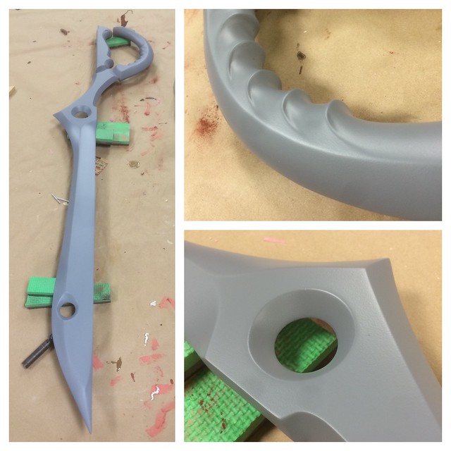
Many passes of bondo, sanding and primer followed as the shape was refined and smoothed out.
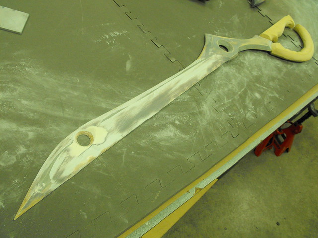
The small hinge part on the handle was cut from a block of urethane foam. This would be cast separately to hide the pour spout on the blade.
After the last coat of primer, the blade was wet sanded and waxed in prep for moldmaking.
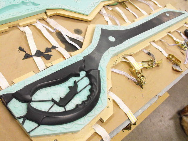
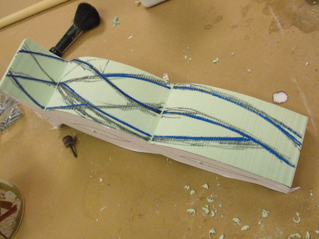
I decided to mold this as a large box pour. The scissor was supported by some wood blocks to ensure it was level, then a clay dam was sculpted to the blade edge to create a parting seam.
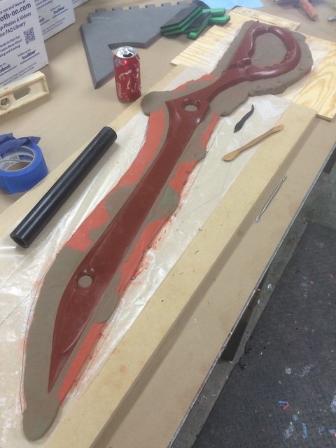
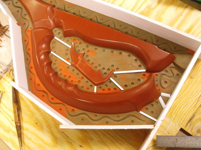
Foamcore panels were cut and hot glued in place to create the edges of the mold box, then registration keys were cut. The squiggle technique is something new I’m trying out, seems to work pretty well so far!
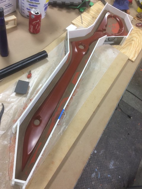
The small hinge piece can be seen on the blade handle interior in this shot. Square styrene blocks stand in place here as mold sprues. As the casting is filled with resin, these channels will also fill in the small hinge part.
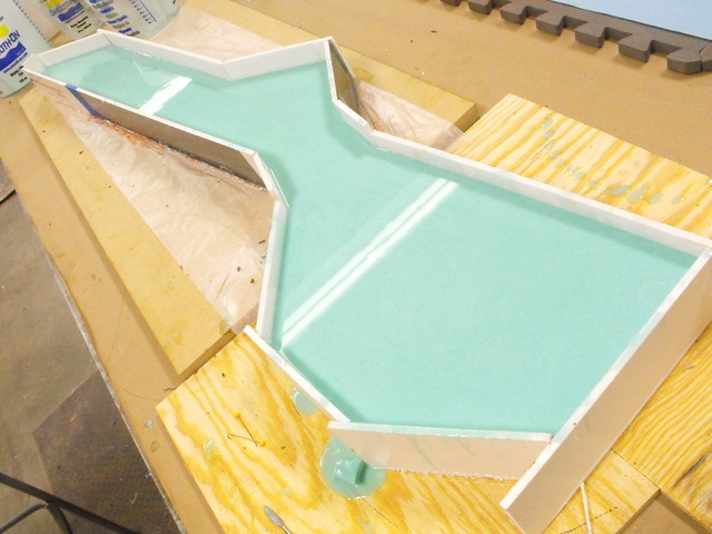
The first pour. I’m using Smooth-On’s Mold Max 40 silicone for this mold.
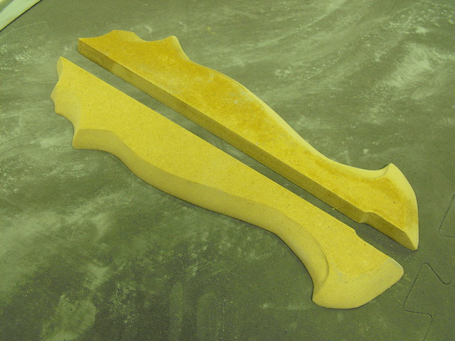
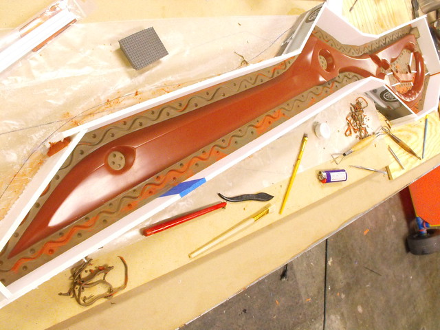
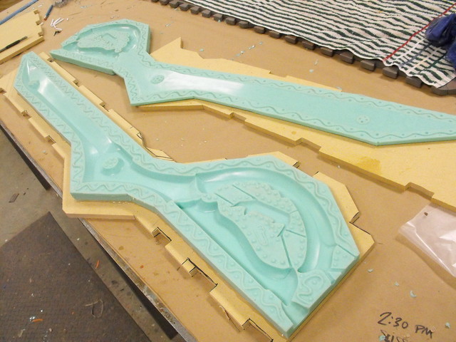
After the first half cured (24 hours) the mold was flipped over and the clay removed.
Mold walls were re-made and the second half of the silicone was poured.
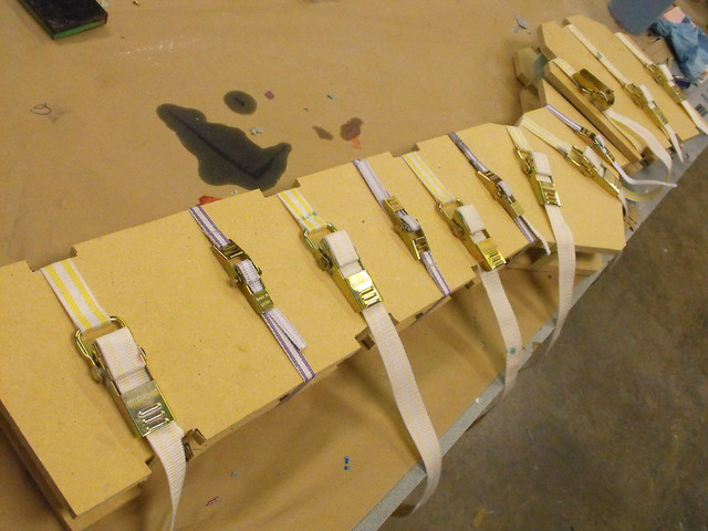
To keep things aligned and square, I cut two large panels of MDF to sandwich the mold. These are held firmly in place with cam lock mold straps.
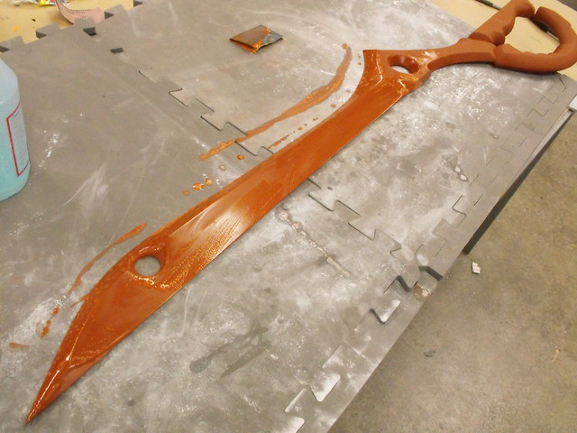
Here’s the first pour! This was done in Smooth-On ONYX urethane resin. I chose this because ONYX is slightly more rigid when cured, and I was hoping the blade would be dense enough to hold shape. It turned out to be a little wiggly. Not bad, but not what a sword should be.
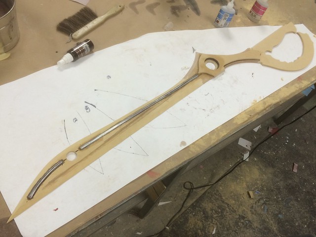
For the next cast I poured 4oz of urethane into the mold and allowed it to cure. A bent metal rod was then placed on the cured plastic, then secured in place with more urethane and allowed to set while the mold was assembled. This was done with Smooth Cast 320.

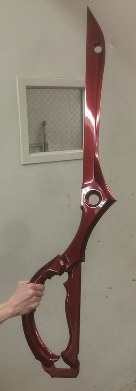
Afterwards, the remainder of the blade casting was poured. You can see the separate stages in the different colors of this casting. The finished part was way more rigid. If you’re interested in painting your own, I have castings available here!
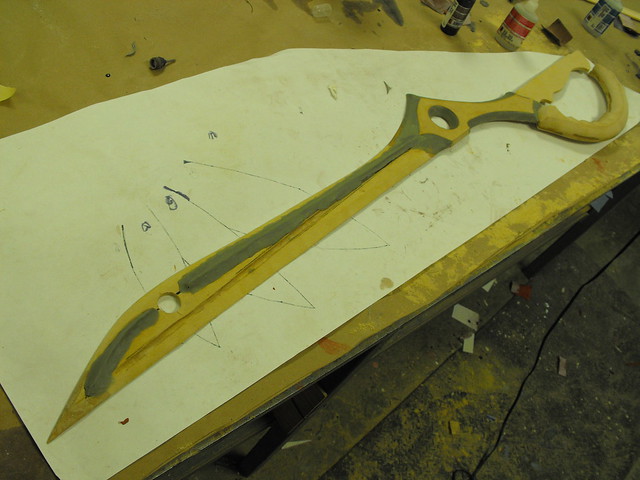
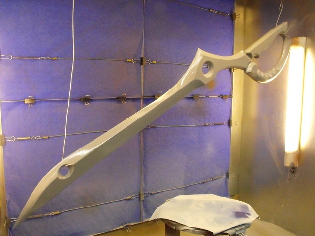
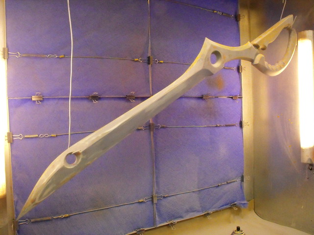
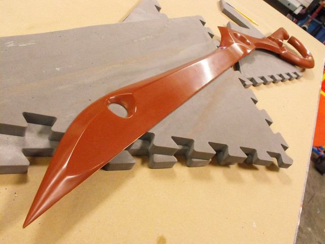
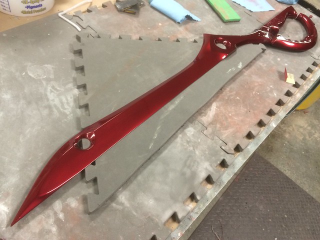
The blade was primed with 2K urethane primer, then wetsanded in prep for paint.
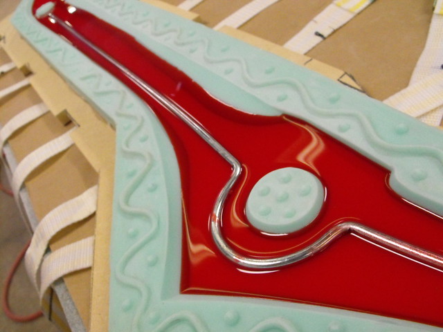
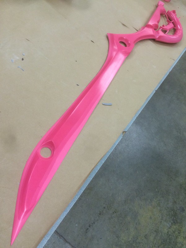
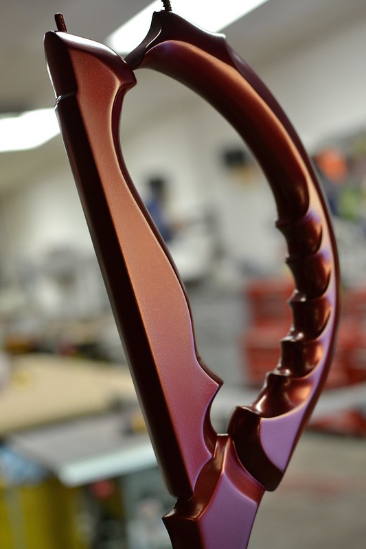
Basecoat for the blades went wonderfully. During this project I was trying out a bunch of new HVLP materials. The bright red blade was painted with Createx Wicked Colors, while the darker one was coated with House of Kolor Shimrin paint.
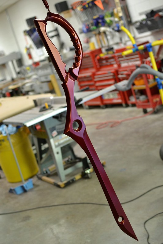
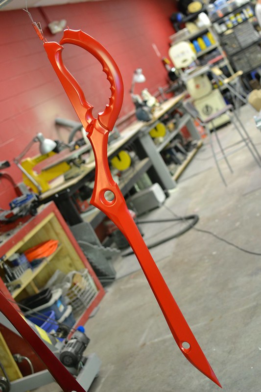
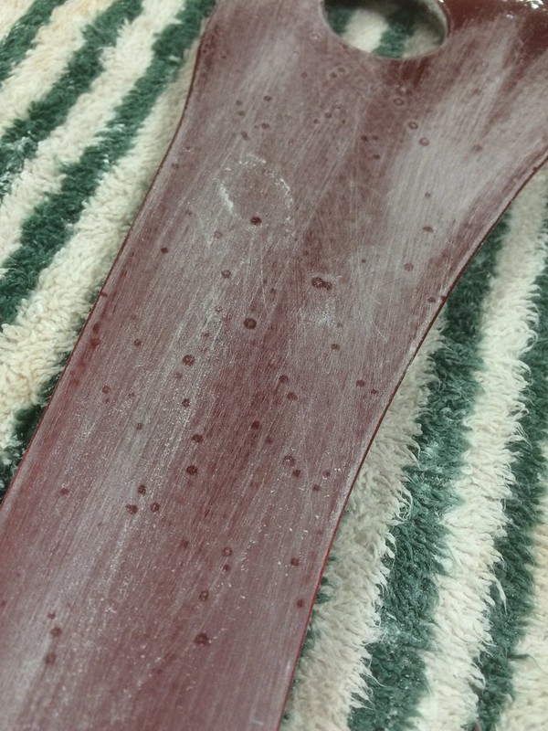
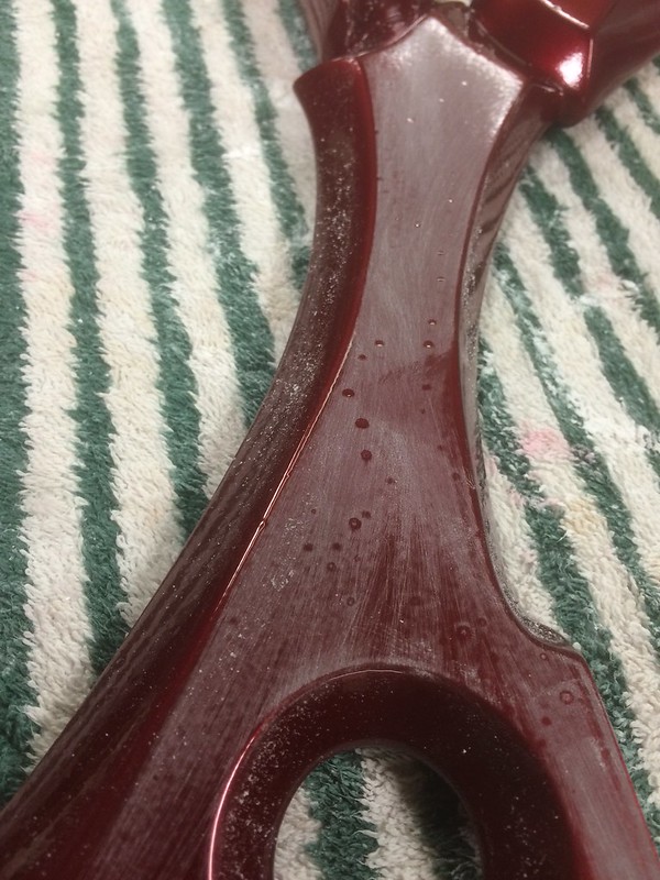
The clearcoat was a nightmare. Urethane clear gives a very high gloss shine and is extremely durable, but every time I applied it I would get terrible fisheyes in the paint. A fisheye is a ring of paint or clear that seems to pucker and make a crater in the finish. It is usually caused by grease or oil contamination, moisture, or excessive dust.
I tried the following to rid myself of the issues:
- Desiccant filter in line with my air supply hose to my spray gun
- Moisture trap on air line (two different brands)
- New silicone-free air line
- Grease and wax remover wipe-down before painting
- Full dis-assembly of spray gun with lacquer thinner cleaner on all parts
- New HVLP gun
- Tack cloth wipe down of all parts
- Fisheye reducer additive to clearcoat
- Two different brands of urethane 2K clear
In the end, the solution came to me at 4am. I had sprayed a very small batch of clearcoat as a test piece onto a scrap piece of plastic, but I applied it with my airbrush instead of my HVLP gun. My airbrush compressor doesn’t have the fancy filter or new air line, but the paint turned out great with no cratering. The only difference was that I mixed the paint in a small medicine cap type cup instead of my larger pint buckets.
After this, I wiped the mixing cup interior down with wax and grease remover. It turns out that the cups still had trace amounts of mold release on their interior surface as a manufacturing byproduct. Wiping down the cup interior did the trick, and clearcoat has sprayed perfectly ever since. An essentially free solution to a problem I spent nearly $1000 to diagnose. Go figure.
Back to the swords! I spent a lot of time wet sanding out fisheyes before finally getting an acceptable coat of clear. After a pass of wax then gluing the hinge part in place, they were finished!
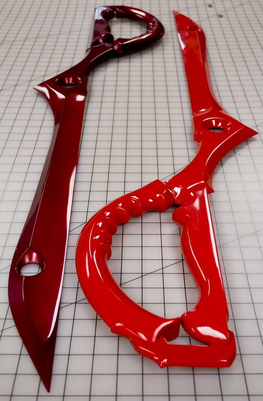
The bright red blade went to my client, and the darker red one was auctioned off at Desert Bus for Hope 8. It raised $8000 for the Child’s Play Charity!
Here’s some finished shots. That shine was a headache, but so worth it.
You can check out some higher resolution photos in my portfolio, and check out more build images on my Flickr.
Thanks for reading!

Magister’s Staff, Dragon Age
It’s been a while since I made a staff, and the last iteration was from a fairly low resolution MMO that debuted back in 2002. A cosplayer attending DragonCon 2014 asked for a piece to compliment her upcoming Dragon Age costume, and since I’m a massive fan of that franchise, I jumped at the chance. If you’d like to have your own without all the sculpting and molding insanity, castings are available here!

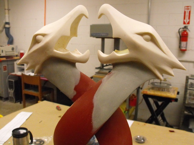
Recently I’ve been trying to polish my somewhat rusty clay sculpture skills, and I thought the organic shape of the bird-like snake heads at the top of the staff would be a good simple shape to practice on. I started by making an armature out of a couple cross-sections of acrylic, mounted to a wooden peg as a base. This was roughly skinned in Chavant NSP Medium weight clay as I got the shape blocked out.


This shape was refined with various hoops and rakes to smooth out everything as much as possible. I also added a couple plastic bearings for eyes and fiddled with the “eyebrows” for way too long.


I needed two copies for the staff head, so a simple block mold was made and cut in half with an exacto to make a dirty 2 part mold. The halves were poured first, since the teeth on the beak of the sculpt have significant undercuts and this mold had no vent channels to get rid of trapped air. After the copies were made, a bit of sanding ensured they were smooth and crisp.


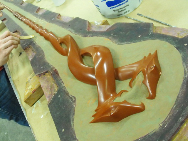
Since this is modern gaming, we can’t just have the staff be a simple wooden dowel. Almost the entire length of the piece is a double helix twist of the snake bodies. I’m a lot better at carving than sculpting, so I grabbed a chunk of 10# urethane tooling board and cut out a rough profile with a few sharpie lines to guide me.

This was reduced to a sort of square spiral with a series of sculpting hoops and chisels, then refined freehand with rough grit sandpaper until the snake bodies took shape. The cross sections of these parts are a rounded triangle that rotates as the spiral contracts. Sounds like a headache, but it was actually a lot of fun to carve.


With the upper section blocked out, another chunk of tooling foam was turned down to round stock before the next pass of carving happened. This smaller section was a bit easier since the shapes are mostly just repeating down the length of the rod.


Both carved urethane foam sections were glued together, attached to a 3/4″ wooden dowel at the base, then skinned with a brushed-on coat of Smooth-On’s EpoxAcoat Red. This epoxy “skin” is denser and more durable than the foam, and can also be smoothed out a lot more than the foam to make prep for paint easier. This isn’t structural, but it will keep the foam from being dented and deformed during the remainder of the sculpting process.


At this point the snake heads could be affixed to the rest of the staff. I mounted them to thin sections of steel wire, which allowed me to fiddle with the placement even after gluing the pins in place. The wire could be bent and articulated to make sure that both heads sat at the proper angle and were both on the same axis before making the mount permanent.

Once the placement was satisfactory, the upper edge of the staff was blended into the heads with apoxie sculpt. Apoxie was also used at the bottom of the spiral to sculpt the small curly “tails” of the end of both snakes.

Primer! There’s a lot of sanding and little filling of small dents and divots, but that’s largely boring to look at. Short version, I worked a lot on this to make things smooth.


Sculpting this piece was actually simpler than molding it. This would be the largest and easily most expensive mold I’d made to date. This would be done by matrix molding; a process where the outer shell of the mold is first created over a clay sculpt that represents the eventual flexible silicone mold. Pictures show this better than words, so here’s a step by step.
First, the staff is wrapped in plastic to ensure it isn’t damaged or dirtied by the clay, then water clay covers the entire sculpt. In this photo, the staff has been embedded into foam board to create a seam line, as this will be a 2-part mold. The clay should be sculpted into the shape you want your final silicone mold to be. You have to account for mold thickness as well as registration keys, shown here as crossing thick lines. The cardboard tubes are pour spouts; once the outer mold jacket is finished, this is where the silicone will be poured to create the mold.

After the clay is shaped, it is sprayed with mold release then brushed with epoxy. This is Smooth-On’s EpoxAmite 102, which gives a lot of working time to ensure a proper coat. The first pass has been tinted and thickened to create a gel coating that’s easier to see. The large trapezoid shapes at the perimeter are registration points for the halves of the mold jacket, ensuring both parts will go together in proper alignment later.

A trick I learned from my master mold making friend Frank Ippolito is to use Free Form Air in the recessed areas to make the surface of the mold smoother. Free Form is an epoxy clay and will bond to EpoxAmite and EpoxAcast. This makes laying down the next layers – fiberglass mat and cloth – easier since the cloth doesn’t have to conform to very complicated surfaces. This makes for less air pockets and a much more durable mold jacket.

Fiberglass cloth is added in several passes to give the jacket strength and rigidity. For a mold this size, I also bonded some steel electrical conduit for even more rigidity. Any amount of flex would result in warped castings.


After the first jacket half was completed, the mold was flipped, cleaned out, then the staff re-clayed for the second half.

With both halves complete, it’s time to pour the rubber. The master sculpt is placed back into one half of the jacket and embedded halfway into clay. This both keeps the sculpt in place during molding and also will create the seam line for the 2-part mold. Registration points were also added, though in retrospect the billions of dots weren’t the best route. I’ve changed this approach since making this mold, with you’ll see in future project blogs. Special thanks to the God Save the Queen Fashions summer intern Atelier Heidi for her assistance in smoothing out this lake of clay and setting up this mold for silicone.
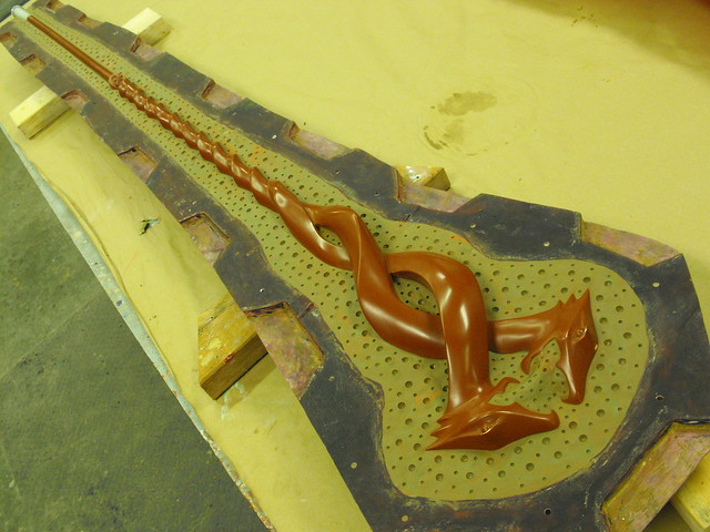
In the photo below you can see a lot of little clay blobs covering the mold jacket. These are plugging vent holes. When the silicone is poured into the cardboard tubes, air trapped in the void between the jacket and the master sculpt will need some place to escape. Small holes are drilled into the jacket to facilitate this, then plugged with clay when the silicone reaches the level of the vent. It can be a little stressful to plug all these while your expensive rubber comes streaming out, but they’re absolutely essential to a successful matrix mold.

Earlier I mentioned the snake heads would be difficult to cast because the “teeth” on the beak wouldn’t have proper vent channels. In order for these undercuts to vent trapped air during the casting process, a blind plug was made that fits into the cavity formed by the mouths of the snakes. A blind plug is a third section of a mold that is held in place on the interior and can only be removed after opening the other parts. This was made by sculpting a clay wall around the mouth openings after the first part of the mold was poured, then filling it with silicone. I went with Mold Max 20 on this, since the plug needed to be able to squeeze through the small openings in the cured castings once the parts were finished. The rest of the mold was done in Mold Max 40 for added rigidity.


Like I said, more complicated than the actual sculpt. Vent channels were added to this plug after curing so the teeth could be cast without trapped air.

Plug finished, the second half of the mold was poured, then this silicone monster was done!

I went through a few tests before setting on a good approach for the production castings. These are poured in stages with a 4′ long 5/8″ steel bar embedded into the length of the staff to add rigidity. Here’s the first successful pull! This casting was done with Smooth-On’s Smooth Cast 320.

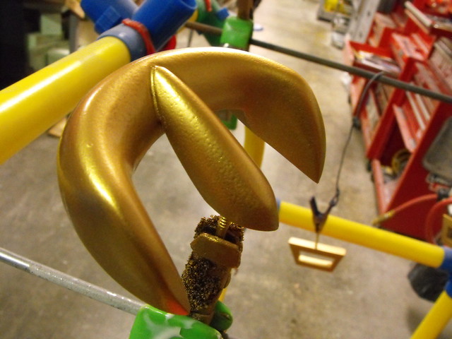
The little egg that the two snakes are fighting over was turned down from a block of dense urethane and sculpted with a pair of divots on the top and bottom. These align with the tips of the snake beaks (sure, I guess. I’ve run out of terms here) so that the finished cast gems are held in place with the tension of the jaws.

A quick box mold was made and the gems were pressure cast in tinted Smooth Cast 325.


I made two finished castings: one Magister’s Staff in silver and a “Corrupted” version in dark red. The silver version was painted dark gray, with shadows and highlights airbrushed on in various metallic enamels. The red version started out flat black; red hues were added with airbrush acrylics to give the piece more depth. I also used some red pearl metallic filler mixed into the clearcoat. This is usually a urethane resin additive, but it worked really well to give the staff some shimmer.


After clear coat, the gems were pushed into place (I slipped putting the yellow gem in and one of the teeth took a big chunk out of my thumb…) and the staves were complete!

You can see higher resolution photos in my portfolio, and more progress images are available on my Flickr.


Thanks for reading!

All of the products listed in this write up are the products that I used and can recommend. Some of them are provided as Amazon affiliate links, which help support Volpin Props.
Captain Ahab, Sunset Overdrive
Back in June I got an invite from my buddy Frank Ippolito to fly out to LA and visit E3. As I’m someone who has a passing interest in video games, I bought a plane ticket immediately. E3 was a great time, and I spent a lot of my hours on the floor walking from booth to booth, annoying the people working there by asking if they had any interest in hiring me to make props for them. Schmoozing isn’t my forté; I spend most of my time alone in a large concrete hallway filled with paint fumes. Some companies were great about letting me chat with developers about potential projects (hey Bungie and Bioware!) while others had information kiosks staffed with stern-faced gatekeepers tasked with keeping the important people far away from the unwashed ground-level attendees (looking at you here, 2K.)
One of the companies I harassed most fervently were the fine folks at Insomniac Games, and by matter of proximity, most of the people at Microsoft. The Sunset Overdrive booth was packed throughout the entire convention and I stopped by every few hours to chat with anyone who would give me a few minutes. This eventually led me to a twitter conversation with the Senior Community Manager at Insomniac, who said they’d been looking at having props made but hadn’t picked an artist yet. BAM!
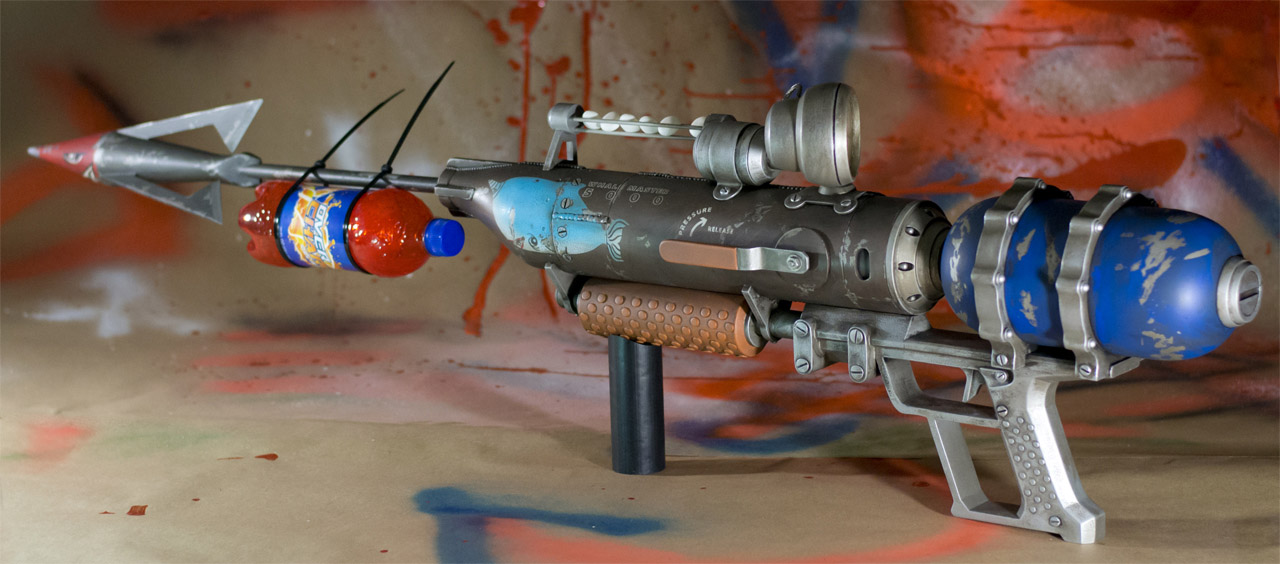
This is how I ended up getting a phone call about 5 weeks later asking for two very detailed replicas from the Sunset Overdrive universe to debut at PAX 2014. I had three weeks, so I partnered up with another local prop shop – Hex Mortis – to make it happen. The first build – the Captain Ahab – is an air powered spear gun with a harpoon tethered to a bottle of Over Charge Delirium XT. There’s also a rail filled with Mentos on the top of the gun. The idea is to load up the mint before firing, turning the harpoon into an explosive round. Like everything in Sunset Overdrive it’s huge, gaudy, and way over the top.

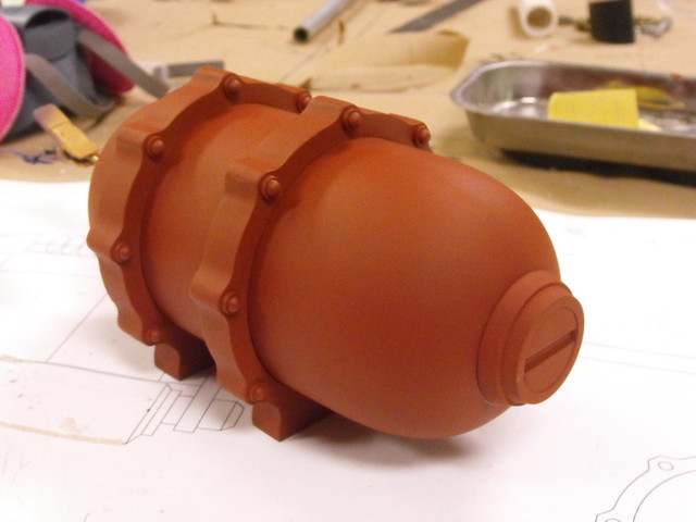
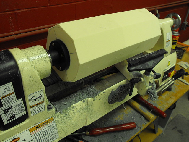
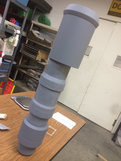
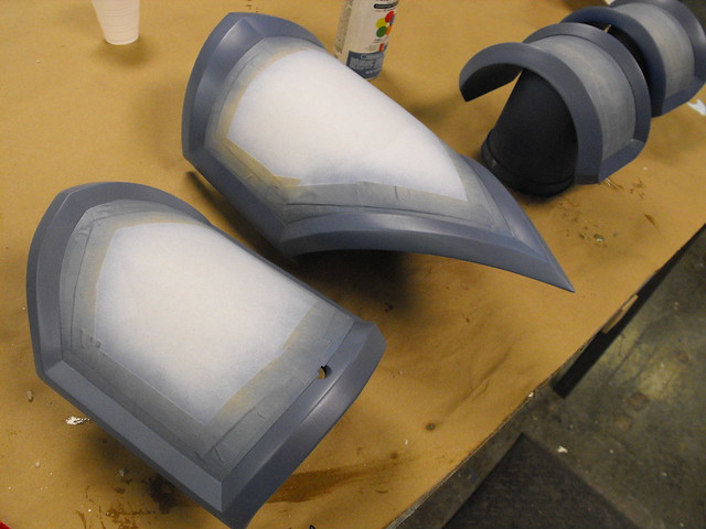
I started the build on the lathe, turning the parts for the large rear pressure canister out of high density tooling foam. This was vacuumformed in white styrene to make a rigid shell.


This rear tank has a couple little fittings on it front and rear, which were also turned from urethane foam. These were much higher density since it would be used on the final prop. No time to make molds!


Acrylic trim rings were laser cut and slipped over the tank to simulate the pressure/mounting bands. My laser cutter can only cut .220″ plastic, so each piece was trimmed three times then glued together to make thicker parts.

There are a lot of faux rivets scattered around these components. For the trim rings, I glued metal washers onto plastic BB pellets then sanded the back side flush to make the studs seen below. On the larger tank flange, I used the tops of electrical crimp connectors.

For most of the rest of the gun assembly, I scoured the “tube and pipe” sections of McMaster-Carr looking for proper diameter stock. The main barrel chamber is acrylic tube, while the harpoon shaft is fiberglass rod. The lower grip section is PVC with a smaller PVC pipe used as the support rod. Real hardware was added in certain parts to give the plastic tubes a bit more believability.

More high density foam was used to turn the harpoon tip. As it’s pretty easy to dent this stuff on its own, I painted a layer of epoxy resin onto the surface of the tip before adding the fins/hooks. These hooks were made from acrylic, though in retrospect something a little less brittle – like ABS – might have been a better idea in the interest of durability.


The lower grip needed several dozen small raised dots on its surface, which I marked out by making a drill jig out of a piece of styrene. This was a flat shape with a bunch of holes in it that was taped around the pipe. I used a drill to bore out all of the surface holes, then glued rivets into each one individually. This took forever, but the result was worth it!


With the deadline being so short on this project, I was pushed a little out of my comfort zone on a few elements. Namely, 3D printing. I haven’t had the opportunity to work with filament printed parts before, but in the interest of time a few pieces were outsourced. For the Ahab, this meant the grip, forward barrel reducer, and gauge stalk.


Unfortunately there were some communication issues regarding the build scale and the parts arrived about 10% too small. I had to perform a bit of creative surgery to get things to line up. The grip was extended by about 1″ with some sintra inserts, and the barrel reducer was flared out with a generous helping of body filler.


At this point I had enough parts to make a rough, precariously-balanced mock up of the final result. This is an integral step in my process, because otherwise I’m just looking at a pile of parts and motivation can be tough to come by!

ABS 3D prints require a lot of clean up, and by the end of this sand/prime/repeat dance I was really wondering if I’d saved a lot of time after all. For more complex shapes like the High Fidelity rapid prototyping makes perfect sense, but a broad flat shape like the grip here would be easier and faster to scratchbuild. Ah, learning new techniques!


For the myriad of weld lines along the main tube, I used some 2-part acrylic cement dispensed through a narrow mixing nozzle. Just add a bunch of little blobs all in a row for instant faux welds! The smaller welds along the front fins were added with Testor’s contour putty.


The standoffs that hold the lower grip in place are more laser cut .220″ acrylic. Since the main tube is also acrylic I was able to weld these parts together with acrylic solvent, essentially making them one component. Way more secure than glue.

There were only three components left to build now: the two mint holder parts and the valve lever. If you’ve been following along so far you can probably see what happened here. More turned tooling foam, a bit more laser cut acrylic, and some sintra sheet. I made the valve lever a static piece but later found out that doesn’t matter to some people, who will try their hardest to get it to turn anyway. It snapped off the first day of PAX, and I fitted an aluminum bar for its replacement.


I did have a couple of these parts made as ABS prints, but decided the clean-up wouldn’t be worth the effort. Nothing against 3D printing, just easier to scratch build sometimes!

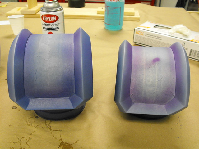
Time for paint! A few pieces in this shot jumped the gun, but most everything was given a fresh coat of primer before going into the spray booth.


Ahab has a pretty heavily weathered paint scheme marked by a ton of chipped finish and lots of grime. There’s a ton of surface variations, so layering was the order of the day. Parts that needed a metallic base were first painted with Rust-Oleum hammered silver enamel. In the shot below you can see a few pins sticking out of the surface; these serve as mounting pegs and make glue joints much stronger than if you’d use just adhesive alone.

The tank and pressure chamber needed to look like steel components with flaking surface paint, so chipped areas were masked off with automotive wax before proceeding to the top coat color. Anywhere you apply wax will repel paint, and the top color can be flaked off with a fingernail once the paint cures. In the photo below you can see the wax as a white gel on the surface of the part:

Here’s the same part with a coat of metallic brown paint, after the top coat has cured. The waxy areas (most visible around the flat head screws) look rough and pockmarked.

This photo shows the part after the wax and dried paint has been scraped away. You can use your fingernails for this, or a stiff nylon bristle brush. It’s important to clean off all the wax before proceeding with your paint and weathering, as it can prevent further layers of paint from curing in these same areas.


Most of the basecoating process followed a similar pattern. Simpler parts like the handle and gauge were painted in flat silver with weathering to come later.

At this point I assembled the gun to its finished state in prep for the finishing coat of weathering. Retrospectively I should have done the below stencil steps first, but ah well.

The Ahab has a lot of stencils on its surface. Labels, a decorative logo, and an obese derpy narwhal mascot. The harpoon tip is also an angry little guy I really like. The more complex stencils were laser cut from some contact paper, then airbrushed onto the surface. Double-masking the “WHALE MASTER 5000” logo took some time.


The little fat narwhals were masked off and gradient painted for their little pudgy bodies, then detail lines were hand painted for the eye, fins, mouth and horn. Before painting I also wax-masked off chipped areas to match the brown finish below the stencils. These chips were scratched away once the surface coat was fully cured.


A similar process followed for the happy little spear head. Most of this was hand painted, with the perimeter masked off in more contact paper.


Grime time. Lots of layers of grit and dirt were simulated with an airbrush and various washes of mixed browns. The Ahab is a really filthy gun.


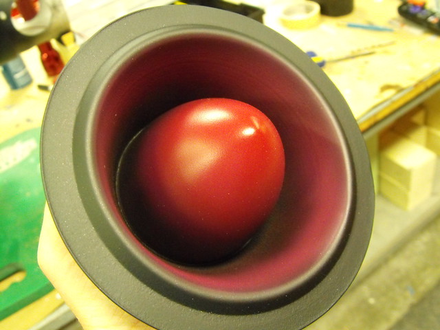
The faux drink on the spear was made by slush casting orange-tinted Smooth Cast 325 inside a soda bottle. This created a hollow casting with trapped air bubbles that simulates the look of liquid really well without all the unnecessary weight. The label was printed to adhesive-backed vinyl.


I also had the gauge face printed to vinyl, with some weathering built into the printed file. This was adhered to a styrene disc and the pressure needle was laser cut from thick paper. A grimy clear acrylic disc finishes off the look. There’s a TON of pressure in this gun!

With weathering complete, the gun was sealed with flat acrylic clearcoat. In order to facilitate shipping, the harpoon was built with a threaded rod at the end so it can be removed for crating and shipment.

And here’s the finished result! Ahab is just under 48″ long but weighs less than four pounds thanks to the mostly hollow and urethane foam construction.

This was a really fun piece to paint and weather. It allowed me to use a lot of heavy techniques that I don’t get to use often.

There are more higher-resolution photos in the gallery, and be sure to check out my flickr for more detailed in-progress build photos.

Thanks for reading!

All of the products listed in this write up are the products that I used and can recommend. Some of them are provided as Amazon affiliate links, which help support Volpin Props.

The Marriott Chariot
You’re never too old for a go-kart.
When I was growing up, there were two things with which my mother forbade me ownership: BB guns and a go-kart. At some point my dad slipped a BB gun under the radar (I think my mom will find out about that when she reads this blog post) but the closest I ever came to owning a go-kart was the time my cousin Chris ran me over with his. Now, here I am at 32 years old. I happen to have my own fabrication shop and I’m looking for an excuse to buy the MIG welder I’ve always wanted. Then I read about the Power Racing Series.
Specifically, I stumbled across this when reading about Jamie Price’s Racing Powerwheels Jeep on Instructables. This looked like just the kind of ridiculous fun I wanted to have.

I happened to be looking for an accessory to accompany my absurd Marriott carpet camouflage costumes from DragonCon 2013. A tiny carpet-themed army Jeep capable of running 20+mph seemed perfect. My mind is a weird place.

So I had a very well-written DIY and an excuse to purchase a welder. I figured finding a derelict Power Wheels would be a snap. I searched Craigslist for a couple weeks but people were asking $75-$100 for plastic disasters covered in kiddie snot. A weekend circuit to 25 different yard sales also proved fruitless. As a last resort I took my search to social media, and that’s when I got a very excited email from Nathan. He sent me the following shot over instagram with the caption “is this okay????”

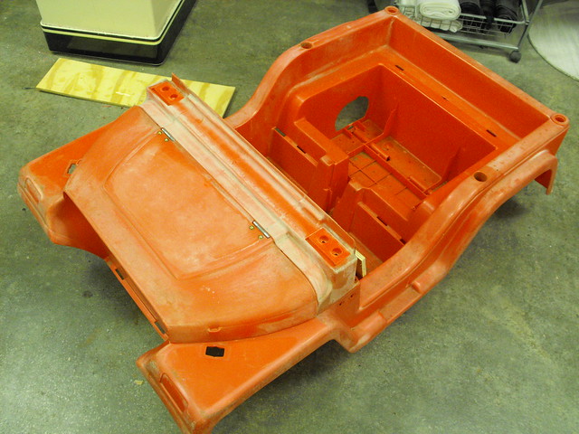
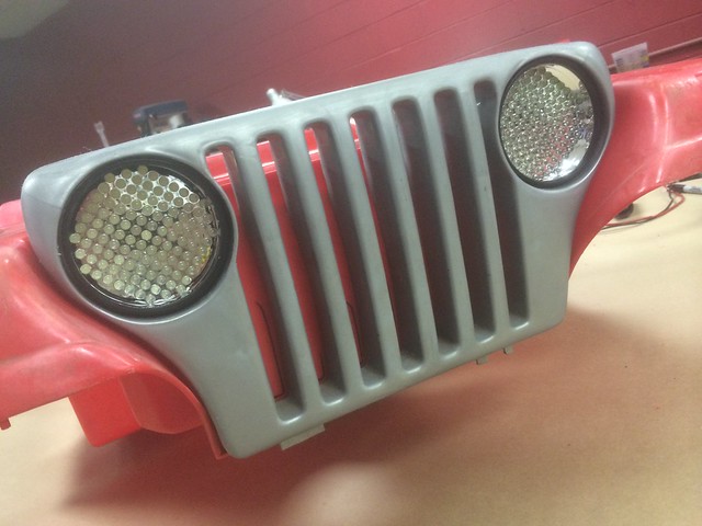
Nathan had spotted this once-red Jeep on the side of the road a couple years ago, and had dragged it home with plans to convert it into a tiny Jurassic Park themed vehicle. Over time it had given up its electronics, tires and a few mechanical components and the only thing left was the body. It was offered for the low, low price of free (!!!) and my search was finally over. Thanks, Nathan!

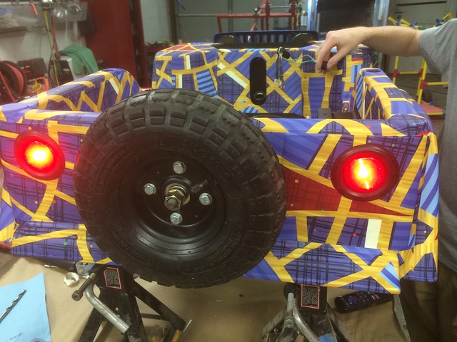
Time and the Georgia sun had not been kind to the old girl, and the decals that covered the body had hardened into some kind of impenetrable crust, partially fused into the plastic. The body was mostly pink, and in some places the polypropylene had started turning to dust. No matter, the vinyl wrap would take care of these small issues.The decals were removed with chisels, scrapers, and a generous helping of industrial strength adhesive remover.
I was missing the headlights, bumpers, some mounting hardware and hood hinges, but I felt confident in my fabrication abilities. First a few small metal hinges to make the hood functional again.

The dash was a huge bulging mass that would seriously impede me ever hoping to fit into the tiny chassis, so most of it had to go. I fed it through the bandsaw and all of the “gauges” went into the trash bin.


With a clean body I was able to take some photos of a few scrawled-on dimensions and create a rough digital model in SketchUp. I used this to plot out the frame and come up with chassis placement for the batteries, motor, steering and controllers. Initially I planned on using L-channel stock from old bedframes, similar to Jamie’s jeep.


Later on I found a steel supplier in Atlanta and ended up buying about 40 feet of 16ga square tube. It was actually cheaper than a thrift store bedframe! Plans changed at this point in favor of a slightly revised chassis.

Motor mounts were machined out of 3/16″ plate steel by my buddy Steven. I sent him these sketches to go off of and the final results (seen later) were awesome.

There’s a bunch of little standard parts that are available in the go-kart world that made fabrication of my chassis much, much simpler. Starting off, I purchased a set of steering spindles off eBay to handle the front end. These are super robust and very well built, too.

I had to carve away a lot of the body interior in order to get it to fit over the axles, but my plan was to retain as much as possible of the original Power Wheels. The under-seat tray, which used to hold the small motor and speed controller, got the heave-ho and I could finally see what the body would look like at my preferred “slammed” ride height. The wheels and tires here are made for a hand truck. They’re inexpensive, which is nice, but I shredded the tires in just one weekend and the bearings were shot, too. Probably not meant for the abuse I put them through.

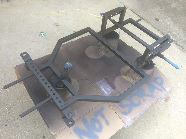
Time to cut some steel! The large hexagonal opening in the middle allows me to keep the stock Power Wheels floor pan.

Tack, flip, tack, flip, tack, weld. It’s been nearly ten years since I did any serious amount of welding and my first few attempts looked like boiled anus. Luckily, I own an angle grinder.

It wasn’t long before I had a rolling chassis! The rear axle is a hollow bar with 5/8″ threaded rods sticking out of either end that serve as axle stubs. Both rear wheels spin freely and independently on two go-kart hubs with double flanges. One side holds the wheel, the other side holds the drive gear. (The drive gears did need to have new mounting holes drilled to match up with the studs on the hubs.)

The chassis passed the “stand on it and jump a little” test, so it was time to sort out the steering. I bought a tiny kid’s bike from a local thrift store and chopped it to bits, pirating the head tube and headset bearings along with bits of the fork. Ball joints and threaded rod were ordered from McMaster-Carr to round out the front end.
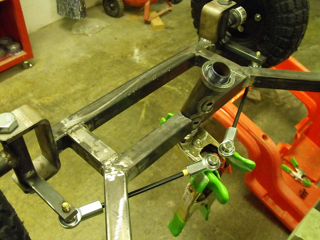

Here’s a close up of the steering pitman arm. I was starting to get the hang of welding again!

Power for the kart is supplied by two 12V, 30AH SLA batteries. Since they’re sealed, I was able to mount them in the chassis horizontally, lowering the center of gravity a bit more. The battery tray itself is a couple sections of L-channel I had left over from my vacuum former build. Bolts welded to the frame hold the tray in place, and this allows the batteries to be dropped out from underneath the chassis if they need to be swapped.

The beefy motor mounts ready for welding. One of these has a notch milled out of the side to clear the band brake on the left rear wheel.


Here’s the chassis at about 90% finished. You can see a bit more welding in the rear; the larger uprights are supports for the seat, while the thinner punched metal gives the plastic body a few places to mount.

A test fit of the body on the frame. For aesthetics, I chopped the windshield by about 3″. Sleek!

Ah, the Zippo test. Anyone who visits Volkswagen modding forums will be familiar with this. I’ve got about 5/8″ clearance between the ground and the bolt for the pitman arm. Plenty of space!

Here you can see how low the body sits inside the hexagonal frame opening.

And here’s the chassis complete! For testing, I dragged it off the loading dock near my shop and scooted around the lot, shopping-kart style. Never rubbed or scraped the ground, so I consider the test a success.

Components were removed in prep for paint, and the chassis was primed and finished with a few coats of flat black enamel. The smaller square tube parts are bumper mounts, and I’m very glad I added those in last-minute – if you notice in the gif at the beginning of this post, the rear bumper makes a great wheelie bar.
Frame complete, it was time to work on some aesthetics. You might ask why I chose to leave the under-hood area empty, when I could easily have added a third battery and ran 36V for more power and speed. Well, remember this is a vehicle made for DragonCon too… and under the hood is where the beer goes!

The front end was missing a bumper and bumper cover. The cover was vac formed from ABS, and a 1/4″ thick 1.5″ dia. ABS tube stood in on bumper duty.

For the seat, a few scraps of plywood were scrounged. Captive bolts mount to the frame using wingnuts, and the lower front section hinges upward to access the batteries and fuses.

Around back, I totally ripped off Jamie’s build and tossed a set of tail lights and a spare tire on the truck.

My dad found a set of LED flashlights at Harbor Freight that fit perfectly in the grille. These things are obnoxiously bright, even after adding three sets of diffused lenses. They’re powered off the main battery using a step down voltage regulator.
Here’s the frame during assembly. I worked by installing larger components first, then routing wires from each part to it’s corresponding part before trimming them to length. The small silver boxes here are the DC motor controllers, purchased super cheap from Amazon Prime! I bought three in case I end up frying one.

Velcro straps or a quick loop of electrical tape make fabricating a wiring harness much easier – just run some wire, tape it down, then continue until everything is in it’s proper place. There’s throttle, battery cut off, illumination, power and ground tied up in here. I need to go back in and wire up an additional on/off switch to the controllers though, in order to stay in compliance with the Power Racing Series rules.
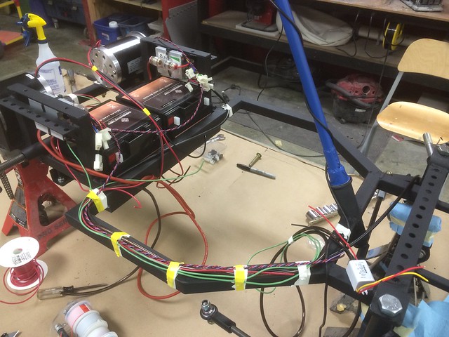
Here’s the whole thing wired up and ready for a test drive! I wanted to make sure it all worked before wrapping the wires and making things look pretty. I hadn’t fully charged the batteries yet, but I tossed the seat on and took it out for a test drive in the parking lot. It was quick. For power I’ve got two 24V 500W scooter motors driving the rear wheels independently

Now, I work next door to a group of very cool guys that do art installation. These guys all think the project is awesome and they’re always coming over to see what new weird thing is being built in my shop. On the other side of my studio are a bunch of humorless knobs who do air conditioning installation, and one of them stood in the window of their space, arms crossed in disapproval. I bet he’s great at parties.

Here’s the wiring, looking much tidier with split loom and velcro straps keeping everything in place. I don’t know if neatness counts in this series (probably not) but in my opinion, proper wire care is all that separates mankind from the beasts.

I did mention the livery inspiration for this particular racing vehicle was to be DragonCon Marriott hotel carpet themed, right? Instead of paint, the full size file (12’x6′!) was printed to vehicle-wrap vinyl by my friend Jim at Atlanta Sign Services. The wrap process was actually done quite rapidly, and this vinyl conforms to tight curves wonderfully. It’s a good thing the cost of the vinyl isn’t counted against my car in the Power Racing Series, since it cost nearly half as much as all the mechanical bits!

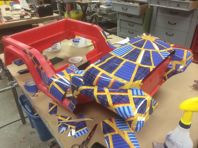
Once the wrap was done, the edges were taped off and the underside painted with black truck bedliner. This stuff is super durable and actually sticks to the polypropylene body extremely well.

The full wrap, complete with matching seat!

I wasn’t keen on the glossy finish of the vinyl, so I sprayed the whole body with flat acrylic to knock the shine down. This helps it blend into the carpet much more convincingly.

The blinding lights were wired up to a switch on the the dash. I was hoping their position close the ground would make them less obnoxious… but it really didn’t.

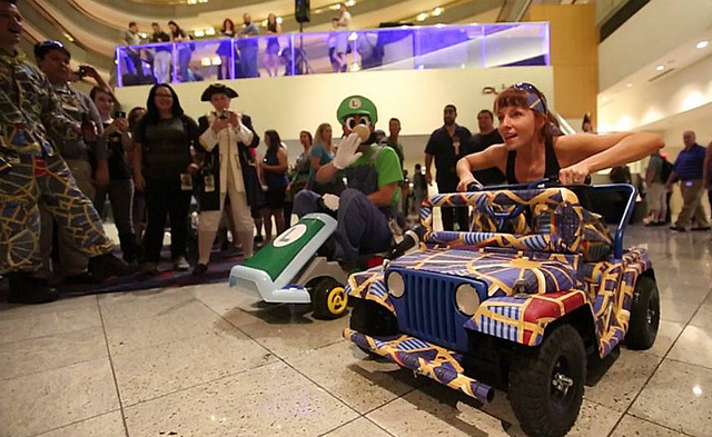
Outside in the sun! This is after a few test laps and discovering the Harbor Freight tires are only “round” in the most general sense, but who cares! I finally have my go kart!


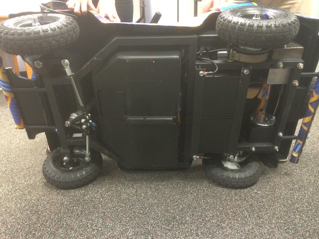
Here’s a view of the underside. Very compact and still fits 100% inside the stock power wheels chassis. Due to the the tires, it’s actually a little bit narrower and shorter than stock.
This thing was a huge hit at DragonCon. Some of the highlights include letting my friends drive laps on the 18th floor (what I’ve decided to call the DragonCon Grand Prix), doing a standing wheelie in the parade while the Red Power Ranger did a running forward flip over my car, drag racing the Turtles Van, and watching my wife thoroughly obliterate poor Luigi in a drag race Thursday night.
My first race is in Nashville on September 14th, and while I don’t think I have any chance of winning, I’ll definitely look great in last place.

For anyone looking to build their own kart, here’s a list of links where I purchased off-the-shelf parts:
- (2x) Double flanged wheel hubs
- (2x) 55-tooth #25 chain drive sprockets
- (5x) Wheel/tire assembly – these aren’t great but they do function. I would recommend finding something more substantial
- (1x pair) Steering Spindles
- (2x) 12V 30aH SLA batteries
- (1x) Band brake assembly
- (1x) Hall-effect twist throttle
- (1x) Handlebar-mounted brake lever
- (2x) 500w 24V Scooter motors
- (2x) 500w 24V Motor controllers
Thanks for reading, and happy karting!
All of the products listed in this write up are the products that I used and can recommend. Some of them are provided as Amazon affiliate links, which help support Volpin Props.
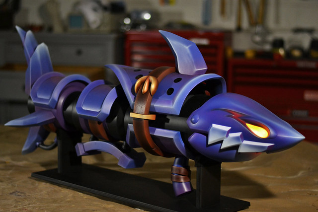
Fishbones, League of Legends
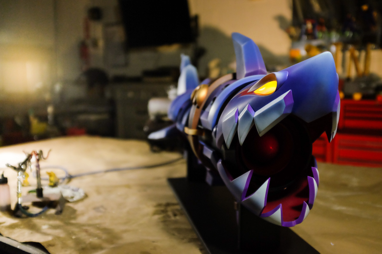
This has to be one of my favorite weapon designs of all time. When Jinx was announced for League of Legends, the shark cannon in her reveal video grabbed my attention immediately, but the change to do a purple/blue paint scheme placed this on my “must build” list. Fishbones needed illuminated eyes and a moving jaw, and became the first project built start to finish in my new studio.

I have to give a huge thank you to LoLKing.net for their spectacular model viewer. Having the ability to call up the models for this project on any computer I had available was invaluable during the course of this project. After some time studying Jinx and Fishbones, I set about making some full scale blueprints (which were later turned into posters as well!). Fishbones was to be 43″ long.
I started with the fun stuff, sculpting the head and jaws first. Both of these pieces follow my standard practice of building 2D cross sections, then filling the resulting cavities with sculpted urethane foam.

Recesses were carved out with a dremel and cavities in the foam were chiseled out to create the teeth areas.

Sections that needed raised details, like the teeth on the upper jaw, were first blocked out with small pieces of sintra, then skimmed with Apoxie Sculpt to make the beveled edges.
After a lot of sanding, I had these forms ready to go.


I made some quick 2-part brush on molds using Smooth-On’s Rebound 25. The first castings were done in urethane resin, and I was very happy to see the jaws meshed together perfectly.


The urethane castings worked great, but I wanted to try my hand at making some epoxy pieces with glass fiber backing. These have the potential to be much stronger and lighter than urethane castings, though they tend to take much longer to produce and also cost a fair bit more. The first step was to paint a gel coat into the molds using Smooth-On’s EpoxAcoat Red. The gel coat forms a detailed skin on the outside of your casting and is applied in a very thin layer to capture detail and reduce any trapped air bubbles. This was brushed on while the molds were separated.
Once the gel coat was semi-cured (wet enough to leave a fingerprint but not enough to stick to a finger) I added Free Form AIR to the deeper recesses of the teeth and eye areas. The later steps of this process involve layering glass fiber cloth along the inside of the sculpt, and sharp recesses like these areas are hard to get cloth to wrap around without trapping air bubbles. Free Form Air is both extremely lightweight and epoxy based, so it bonds to both the gel coat and the subsequent layers.
Finally, glass cloth and EpoxAcast 690 are added to the interior to give the part its strength and rigidity. Only one layer of cloth should be added at a time, and I prefer to use small squares of 10oz cloth, followed by larger squares of a heavier weight cloth in later layers. The molds are still in separate halves at this point.
Once both halves are semi-cured, the molds are bolted together and the seams are treated in a similar process: gel coat, then glass fiber and epoxy. The finished pieces are about half a pound lighter than their urethane counterparts. This may not sound like much, but every ounce counts!
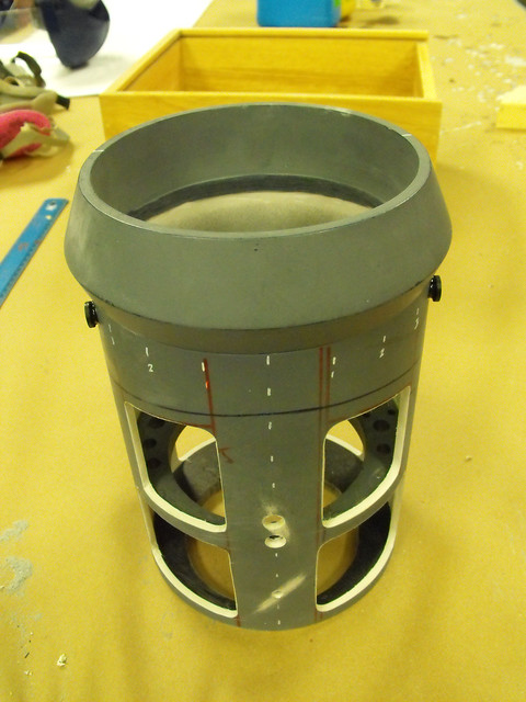
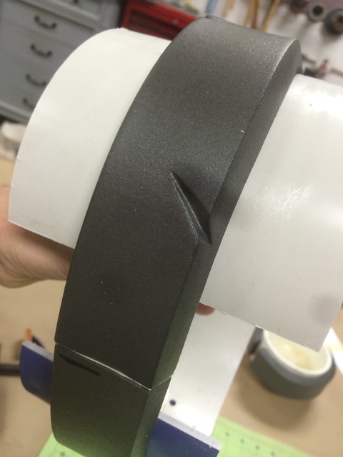
Speaking of weight, Fishbones was on a very strict styrene-and-vacuum-forming diet for many parts of the project. The main barrel piece started out as a large block of tooling foam turned on my lathe…

…which was eventually split in two parts and vac formed from .060″ styrene to make a thin, lightweight shell.


The fins jutting out from the inner barrel were also vac formed in a similar way. The vac form bucks for these are sintra blocks. Thickened methacrylate adhesive was used to make the styrene halves of these parts into one hollow fin. This is some expensive glue, but it’s pretty much a tube of magic when it comes to bonding plastics together. The seams of both parts were treated with MA300 then clipped together to cure. After a couple hours the flange was trimmed off and the edge sanded flush.


Each of the fins is affixed with two bolts that secure it to an interior frame. This is a structural pipe that sits inside the lightweight styrene shell and provides support for all the plates bolted to the gun. In another weight-shedding endeavor I was able to hole saw another half pound out of this pipe, without sacrificing any of the structural rigidity of the part.


That strategy continued to the larger 6″ diameter tube that forms the front of Fishbones’ barrel. Initially things looked like this…
…but once I figured out that much of this would be covered by the armor plates on the gun, I chopped out a lot of material.
The larger armor plates were built from sintra sheeting. Large sheets were first heated in my vacuum former oven before being draped over tubes to take their cylindrical shape.

Each of the armor plates has a triangular-raised perimeter edge. For some parts I was able to make a long thin piece of triangle channel, then glue it to the plates, saving myself a lot of complex sanding later on.

Other parts required more complicated curves, so their raised edge was glued on as a flat bar then sanded down. I started off with my air grinder and a very rough chisel drum. If I were going for a wood texture, this would have been awesome.
This was followed by a dremel sanding drum and eventually hand sanding until all the parts were smooth.


The two contact points on the gun – the shoulder rest and the grip – were both made from solid blocks of sintra. The grip has a large 3/8″ bolt embedded 3″ into its center for additional support, and the shoulder rest has two solid wooden dowels that are used as anchorpoints that secure it to the gun frame.


I also milled out a small rectangular slot in the shoulder rest to house 3 AAA batteries which power the eye and mouth LEDs.

Now it’s time for the party piece: jaw articulation. I don’t have extensive puppetry knowledge so a lot of this was trial and error, and also a lot of imitating similar projects I stumbled across on Google. I sketched out a few dozen ideas and eventually settled on this mechanism. This is the left and right side hinge assembly and pushrods. The ball joints and threaded rod were purchased at a local Hobbytown, and the pivots themselves are laser cut acrylic.

This worked okay on the table, but some issues emerged when attaching it to the jaws. I had initially planned on using the hinge bolt as the pivot arm’s contact point, but repeatedly opening and closing the jaws loosened the bolt and the assembly failed. I added a second rigid pin to the jaw and head to prevent this from happening. Below, you’ll see both the threaded hole for the mounting bolt and the long thin threaded rod, which will be pushed/pulled when the mechanism articulates.
Here’s an interior shot, from top left to lower right. The large bolt holds the upper jaw in place. The smaller silver rod with the black nylon nut is the pivot arm for the upper jaw. The pushrod for this assembly sits just above it, with a brass rod covering the threaded bar to eliminate the spring rubbing against the threads and making an awful noise. The two return springs ensure the mechanism closes at rest when the trigger isn’t pulled back. Just underneath the right side of the brass pushrod assembly is the ball joint that attaches to the trigger; this pulls backward to pivot the large black plate and the attached pushrods. The second pushrod without the brass sleeve articulates the lower jaw. The hinge bolt for this assembly is the small hex head bolt and the silver threaded rod beneath it is the pivot arm.

There’s an identical mirrored copy of this assembly for jaw’s opposite side.

Simple, right?
Here’s a shot from the backside, where you can see the cable for the trigger assembly. After adding the pivot pins, the mechanism works perfectly and is rock solid.
Cool looking though it is, nobody wants to see how sausage is made. I built a dummy rocket head to cover up the mechanism when the jaws are opened. These are vac formed styrene panels held in place with magnets. In case anything in the jaw hinge ever needs to be serviced, this can be easily removed for maintenance. In fact, the entire gun bolts together and can be disassembled into its component parts in case things ever need repair in the future.

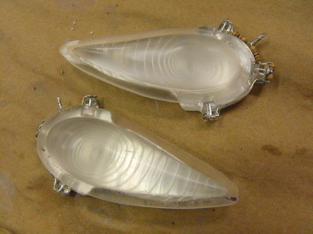
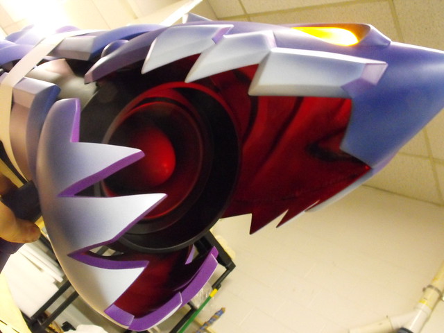
The last major step before paint was to trim out the area for the eyes and sculpt the interior of the head. The eyes were pressure cast from Smooth Cast 325, and I used a small amount of body filler to make sure the mating edge was seamless.


On the inside of the upper jaw, there’s a sort of bone/rib type pattern. This was sculpted in Free Form Air to keep things lightweight.
I spent a lot of time with spot filler and sanding getting everything super smooth before paint. The larger sintra armor plates were painted with filler primer to make filling small divots in the sintra surface easier.

Time for paint! The paint job on this cannon took me about a week. Most of this is new ground for me, but I’m beyond happy with the results. The first pass was done with a Krylon satin blue enamel. Everything was given two coats and was allowed 24 hours to cure fully.


I used more Krylon, this time a gloss purple (the finish doesn’t really matter since I’ll be clear coating everything matte later on) to make a purple gradient across all the pieces. Gradient painting with spray cans isn’t easy and if this were a smaller area of paint I would have done it with my airbrush instead. The enamel base makes top coating much easier though, so I stayed with this technique. To get the best atomization of the paint, warm the can by running hot tap water over it for about 10 minutes before you spray your gradient.
After the gradient paint coat cured for another 24 hours, I started with the airbrushing. I used Createx Wicked Colors for all of the detail work from here on out. The first pass was some lighter blue on the tips of all the fins, followed by a nearly white-blue to outline the polygon edges coming out of these lighter tip spaces. In the picture with two fins, the left part is before edge-highlighting and the right is after. Airbrushes used on this were my Iwata Eclipse siphon feed for larger areas and my Iwata Hi-Line gravity feed for details

The armor plates were masked off in the center areas, as the purple gradient over blue was accurate to the game render. The perimeter lip had a very different paint scheme, which started off with a pass of matte cobalt blue as a new base color layer.
The inner face of the perimeter was tinted purple and the outer face tinted blue. I used the same edge highlighting as on the fins for the very top of the raised lip around the whole shape.
With the masking tape removed, here are the results!


The head and jaw were probably the largest amount of work, and I spent a lot of time tweaking the colors and gradients until I settled on something I liked. The technique was largely similar to everything listed above, but applied with a little less mathematical rational and a bit more artistic liberty.


That is, with the exception of the outlines on the teeth, which were all masked off and painted to give a hard, definite edge.


The dummy rocket head was also given a gradient treatment, incorporating a few accented shadows to better hide the seams on the rocket and shroud when the jaws open.
The last step was a coat of Krylon matte acrylic clearcoat #1311 over all the parts to give everything a uniform finish.

Illumination came next, with the eyes getting a little extra detail. In-game they glow yellow but I wanted a bit more here. It’s atypical for me to deviate from the reference material but this just felt right. I laser-etched a spiral pattern into 1/4″ clear acrylic and backed this piece with mirrored film. Three 5mm yellow LEDs provide illumination and the lines, combined with the mirror film, help to distribute the light evenly without any hot spots. Because of the lens effect of the eye itself, this pattern also appears to follow the viewer as they move around the piece.

There’s also two 5mm red LEDs in the tip of the nose that point inward and illuminate the mouth and dummy rocket. The effect when the mouth is closed is really neat.

I put off working on the belts until the absolute last minute, for reasons I can’t quite remember. The strap itself is made from 3/8″ EVA foam while the buckles are cut from sintra blocks. There was a lot more time with the airbrush here to make sure the shading lined up with the cartoonish appearance of the rest of the gun.

Bolt it all together, and you’ve got a finished shark cannon! (I tweaked the red in the eye recess after this shot was taken.)
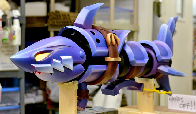
This was a huge project and one of the most complex pieces I’ve built to date. It seems like every new project just keeps getting crazier and crazier. This is the first of many pieces to come out of my new studio, so make sure to follow along for more to come! Until then here’s some finished photos of Fishbones. Photos by my talented friend Dan Almasy.

If you’re interested in reading more details about the build, there’s dozens more photos with detailed descriptions of each step on my Flickr page.

Also be sure to check out the gallery for larger resolution photos of the finished piece.

Thanks for reading!
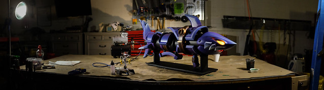
All of the products listed in this write up are the products that I used and can recommend. Some of them are provided as Amazon affiliate links, which help support Volpin Props.

Planet Express Ship, Futurama (part 2)
At the end of part 1, the Planet Express ship was earning its name in shape only; I had a Futurama ship, but it needed a coat of electric mucus in order to look the part. My master sculpt is also quite fragile and will need molding and casting before the parts can be finished and painted.

Moldmaking comes first, and the fuselage was up on deck. It was mounted shish kebab style on a steel rod and slathered in clay. Admittedly I’m still getting the hang of matrix molding, but practice should eventually make perfect (or at least perfect enough)


Matrix molding is a process by which you make the exterior mold jacket first by sculpting the shape you eventually want your silicone mold to take out of clay first. This is then covered in a rigid shell – polyester resin followed by glass fiber cloth in this case – and allowed to cure before opening it up and removing the soft clay surrounding the part you’re molding.


The master sculpt – ship fuselage – is then placed back into the rigid mold jacket and silicone is poured into the space between the master and the jacket, creating the soft rubber mold that will be used to replicate the form.


Like I said, I’m still getting the hang of this so my process is a bit sketchy right now. Specifically, the registration lines are far too tall and narrow, and I neglected to add any pour spouts in my mold jacket for the rubber to be added in later on. Learning is “fun”!
Still, the results are what we’re after here and they’re pretty darn good! The silicone I used here is Smooth-On’s Smooth Sil 940. A little thicker than I’d like for this mold, but if I’d added larger pour spouts and wider registration channels, it would have been fine.

The rest of the molds are pretty conventional block pours like I’ve done many times in the past. Embed the part halfway in clay, pour the first layer of silicone and allow to cure. Flip the part over, apply mold release, repeat.
These ranged from smaller detail parts…


…to much larger blocks for the wings and tail fin.

Typically I don’t add pour spouts until after the part has been molded. I’ve found that trimming pour and vent spouts out with a sharp knife is much easier than trying to sculpt them into the clay while making your parting seam. You will see the lines where I plan on making the pour/vent cuts though in larger molds like the wings. Drawing a line in the clay means I know where to put the registration keys so I don’t have to carve a weird maze between the lumps and bumps later on.

All of the block molds were made with Smooth-On’s Mold Max 40. This stuff is some of my favorite rubber to work with; it’s very forgiving stuff.
A few test pieces were cast in Smooth Cast 320. The smaller stuff has to be pressure cast in a chamber at 60psi to reduce air bubbles. Since gas is compressible but liquid is not, putting uncured resin into a pressure chamber reduces the size of air voids to near microscopic levels. This helps with the amount of clean up needed once the part is extracted from the mold after curing. This was especially necessary for the ship’s engine, since the super thin walls of the thruster nozzles really like to trap bubbles.

The front staircase/landing skid was a somewhat trickier piece. This is a 3 part mold with a plug insert. It’s complex but it means the seam lines are as hidden as possible and there’s virtually zero trapped air after pressure casting.


While these aren’t in the final build of the ship, I went ahead and made a few landing strut inserts for an “in flight” version of the ship. If I ever make one for myself (hahaha) I’ll probably do the flying variant.

Since I spent a lot of time thinking of the final assembly when designing the parts, putting these castings together went pretty quickly. The wings have large tabs that insert easily into the body and the turret just plops into place as well. A couple of other parts required more complex solutions, however.
The staircase skid connects to its mounting plate with four pins – two on each side of the strut. The plate itself screws into the base of the ship, and the skid snaps into place later. The tension of the plastic holds it in place easily.

I chose to use small neodymium magnets for the landing bay hatch. Easily removable but strong enough to not come dislodged accidentally.

Here’s the first completed set of castings awaiting painting and electronics!

Speaking of electronics, let me show you some of the assorted lengths of wire I used. The plan was that each ship – for some idiotic reason I has chosen to build three of them – would have pulsating engines, illuminated wing tips and a drop light on the front stair skid. This would all be controlled by an arduino prop mini and powered by a 5V USB adapter.
I designed a simple LED driver breakout board in Eagle, and had my boards printed by OSH Park. Parts were sourced through DigiKey and soldered together.


Power would be delivered through a jack hidden in the front landing skid. The wire would run up through the stairs and into the main body.

Each wing was drilled out to receive a set of wires and one red 3mm LED. As you can see by the small patches of filler, I wasn’t always able to core these things out first try.


The engine illumination would be handled by several 5mm soft blue 360º LEDs. There are 6 banks of 3, spaced apart and pulsing at random intervals that give the engines the firing look seen in the show. Each bulb was glued to a spacer to keep it centered in the thruster housing, then individual resistors and wire leads were added. I did this 54 times. Then I lost two of them, so I did two more. Woo.

For the wing tips, I made a small mold and cast these in Smooth Cast 325, which dries semi-clear. these act as diffusers for the 3mm red LEDs embedded in the wings themselves.

I also wanted a nice cratered cartoony planet surface for the ship to rest on, so I put a little oil on the rusty clay sculpting skills and knocked this out. I’m not the best organic sculptor in the world but I really liked the end result! The clay used was my crappy cheap non-sulfur stuff I use for making mold walls. This was then molded and a few copies were cast.


One last tiny detail were the ladder rungs next to the starboard wing. These were made from brass tubing and countersunk into the ship fuselage.

It was finally time for paint.
The simpler parts went first. Landing struts and porthole inserts were painted with airbrush Testors enamel, and I basecoated some parts on the ship fuselage.


I was trying out a few new things with the paintwork here. Typically when making space guns, there’s no shortage of black, silver and gray paint. Retail stores didn’t seem to carry the electric mucus necessary for a proper PlanEx paint job though, so I decided to mix my own. I went with Createx “Wicked Colors” paint here, though there was a steep learning curve and I think in the future I’ll probably try their “Auto Air” line instead.
I ran a lot of tests with various clearcoats to get the proper finish and shade to my liking. The lower middle was what I eventually settled on.

Unfortunately I ran into some issues when painting the actual parts. When they say “thin passes” they mean atomized. Just think the paint toward your model. Whisper the paint onto your model with a soft elvish lullaby. There exists somewhere an integer that is somehow more than zero but less than any actual amount observable by man. That is the amount of paint used per coat.
If you overdo it, this happens. The base layer never fully cures and the paint peels off like elmer’s glue off a third grader’s palm.

So I peeled all the paint off the fins, but learned enough to get everything else right. Here’s passes 1, 4, and 8 on the ship body.


Similar work was done to all other Electric Mucus parts

The fins were basecoated a darker green… then the masking began. Over the course of this project, I spent $80 on tape. To get crisp lines when masking off painted areas, spray a light pass of clearcoat across your seam first. This will fill in any of the small gaps in the masking tape that result in feathering or paint seeping under your tape line, leaving you with a crisp clean edge. It also helps to use good quality tape – the stuff I’m using here is Tamiya brand. Pricey but well worth it.


The body of the ship was masked off no less than six separate times for the tan, red, dark green and gray accents. Here’s a few highlights:


Smaller masking details were trimmed with my laser cutter. For the rivets on the fins, I laid tape over transfer paper then cut out small diameter circle masks. Similar curved shapes were trimmed for the masks needed to paint the front windscreen surround.


The final touch was a set of water slide decals I’d had printed for the fins. Despite their white backing the dark green background washed out the colors a lot and I ended up masking off a section behind the decal help the colors stand out.


Unfortunately the process of printing these decals uses some chemical that is wholly incompatible with the clearcoats I use. I tried several different others with little success, and this left the water slide decals very vulnerable to damage. Despite the effort to get them to work, the water slides were eventually shelved and replaced with a set of printed vinyl decals instead.
With all parts masked, painted, cleaned and clearcoated, it was finally…

ASSEMBLY TIME!
I put together a video of this process, since videos are way more fun to watch than a blog is to read. Mainly the parts are held together with Loctite epoxy, however, in retrospect I would recommend 3M Scotch Weld as a better adhesive. Make sure to scrape away layers of paint before gluing together though, otherwise the only thing the epoxy is sticking to is fragile paint and clearcoat.
One thing I would like to point out is my luck in finding a piece of tube that centered the LEDs perfectly in the thrusters during assembly. Electrical connectors, woo!

The LED in the forward strut is one of my favorite accents on this piece. That’s just a single 5mm 45º bulb.

I created three painted bases for the three ships. The green one takes its color palette from Omicron Persei 8, the purple base emulates the colors of Eternium, the Nibbloniam homeworld, and the red/purple base was an exaggerated version of Futurama‘s Mars. There are felt pads where the ship stands to keep the plastic base from scratching up the paint on the landing struts. The bases were mounted to stained pieces of poplar to give the finished piece a bit cleaner presentation.


