Clare’s Armor, Claymore
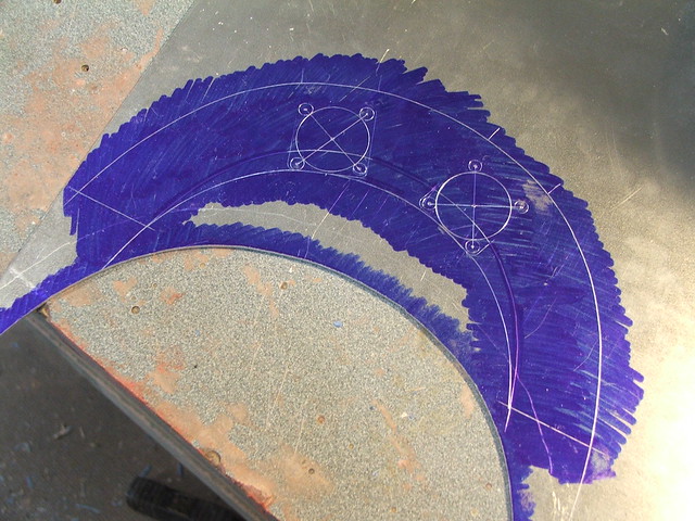
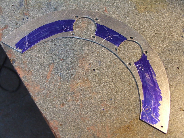
As part of another joint costume adventure between myself and my friend Cathy over at God Save the Queen Fashions (some readers may recall her work on the Daft Punk leather ensemble) I was drafted to create the sword and armor for Clare, the protagonist in the series Claymore. My experience with armormaking was pretty minimal at best, so this was all one big learning lesson for me! While not fully encased in a suit of armor, the Claymores do have many parts that make up their outfit. All told, there are 2 sets of shoulder pauldrons, a chest clasp, a sword carrier/backpack piece, a plate skirt, wrist cuffs, handplates and greaves.


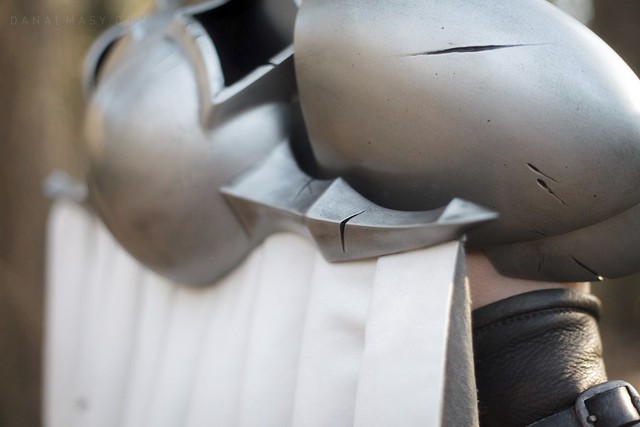
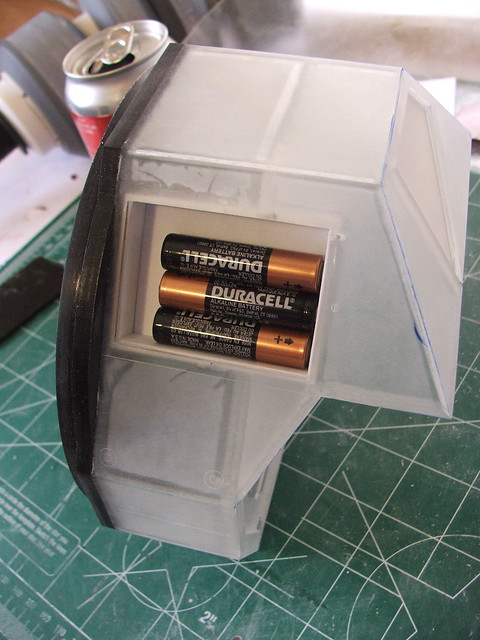
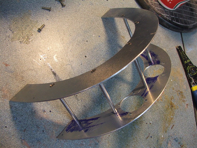
Small machine screws were embedded along the inside of the larger pauldron, and the smaller ones affix to the inside with nuts. This allows them to pivot slightly and helps to increase movement.
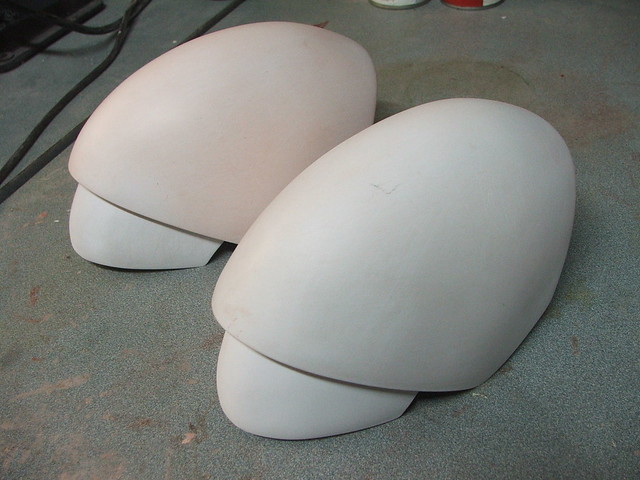
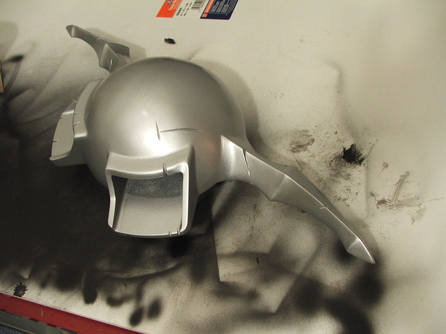
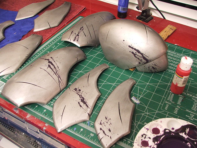
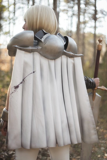
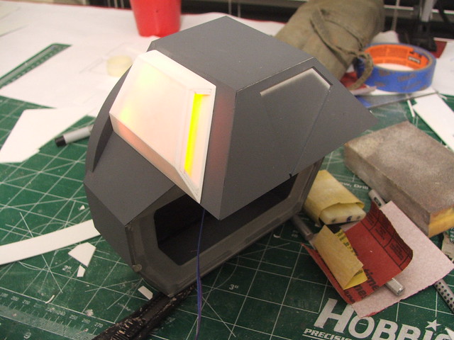
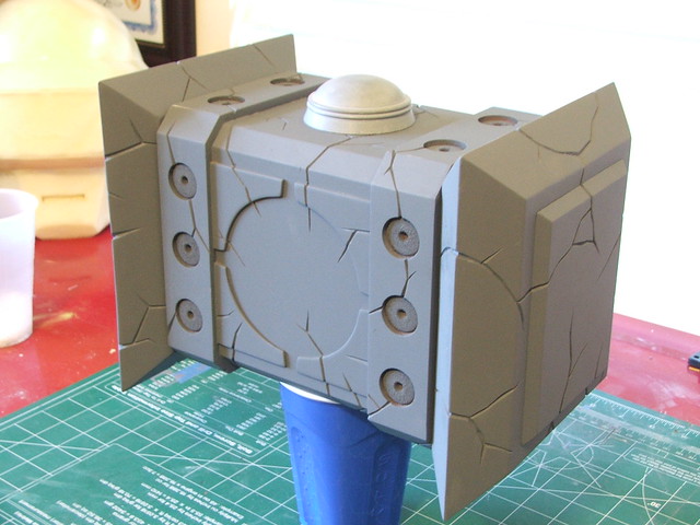
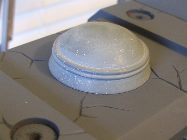
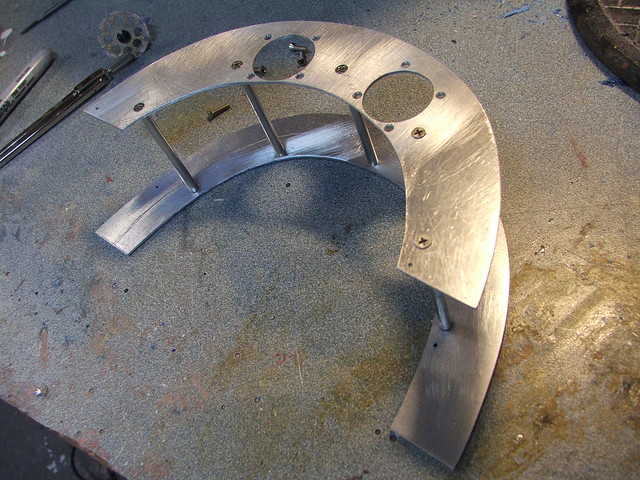
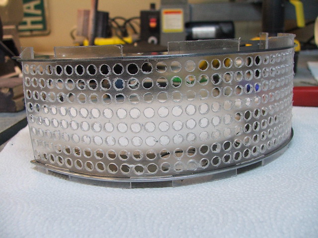
After a guide coat of primer, it was decided to add some damage to the armor. Clare is the “lowest ranked” Claymore in terms of her abilities, and in the anime series, she gets her ass kicked a lot. It only made sense her armor would take some pretty severe hits during her trials.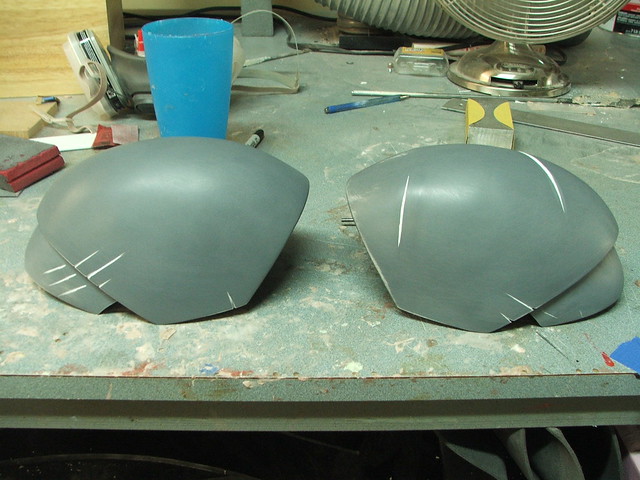 The dome part of the “backpack” thing was pulled in the same .10″ styrene as the pauldrons. This was placed over a sheet of 1/4″ sintra trimmed to the shape of the backpack perimeter. Since the weight of the cape would be hanging off the spiky wing sections on the backpack, it made sense to have the backing plate be one solid piece in order to be as rigid as possible.
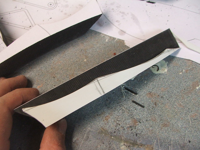
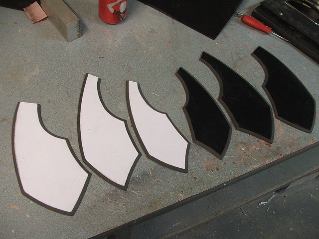
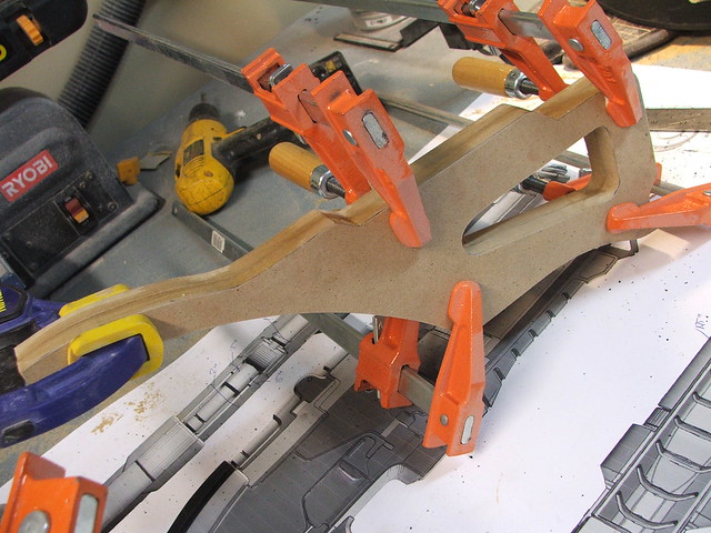
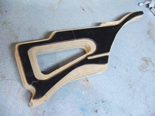
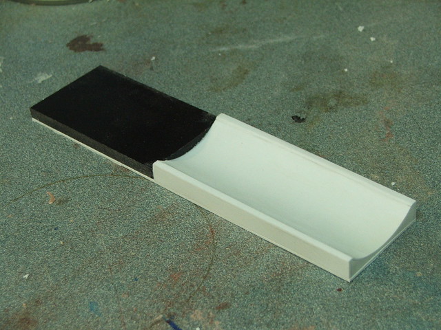
The wing sections were also cut from sintra, and started out as 1″ thick parts. These were cut first on my bandsaw to give them a rough shape, then bisected along their center line.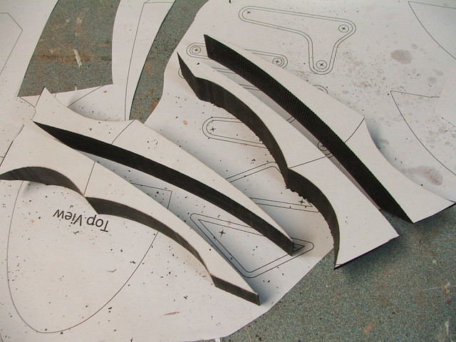 After cutting the center line out, I added a thin styrene sheet between the halves to act as a guide for cutting the profile shape of the wings. After this was added, the two halves were glued back together around this part.
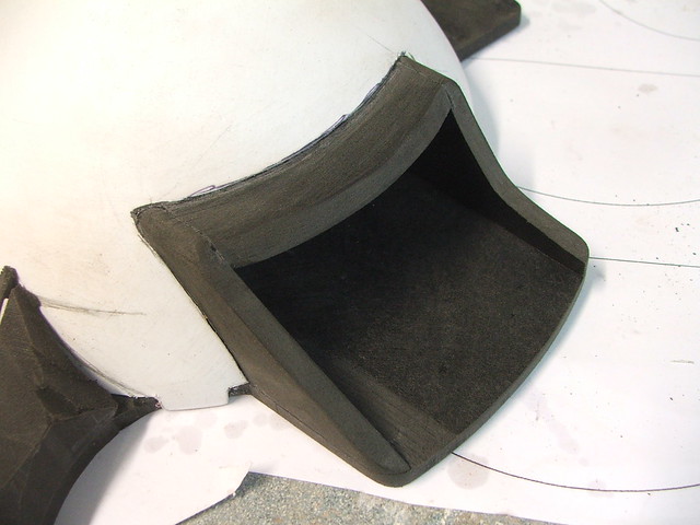
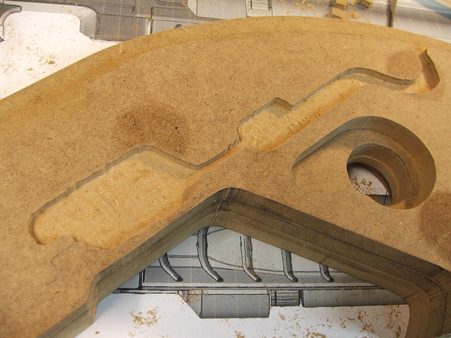
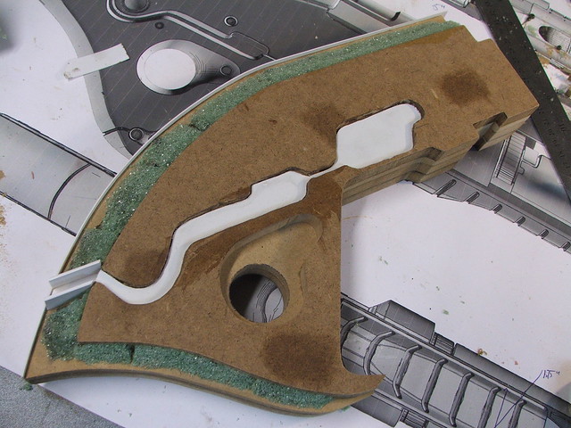
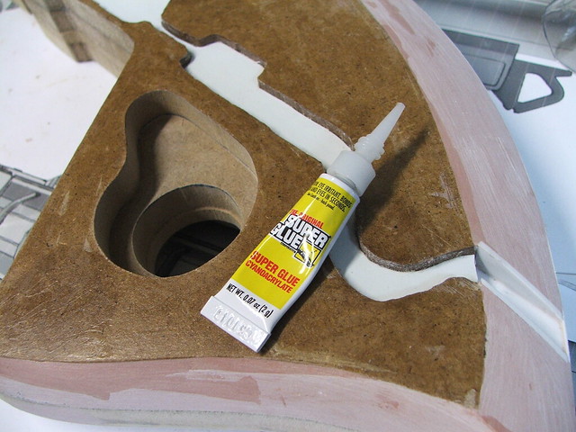
The sintra was rough sculpted into shape with a dremel tool using the center spine as a guide.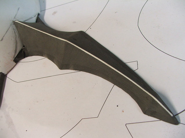 More sintra was used to make the sword carrier sections. While the actual Claymore blade I made won’t fit in these recesses (damn you anime designers!) I do have plans to make a sword “blank” to fill this cavity in the future.
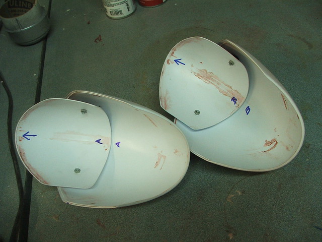
Lots and lots of filler and sanding later, we have a smooth pretty backpack. This got the same scars and scrapes as the pauldrons, don’t worry! I don’t have any pics of it handy, butt here are also 4 blind nuts embedded into the back plate in order to mount this to the costume later on.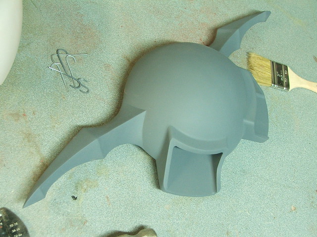 The “battle skirt” (as I came to call it) was made out of 1/4″ sintra sheets. These were first trimmed to shape, then the edges were beveled by hand with a dremel tool.
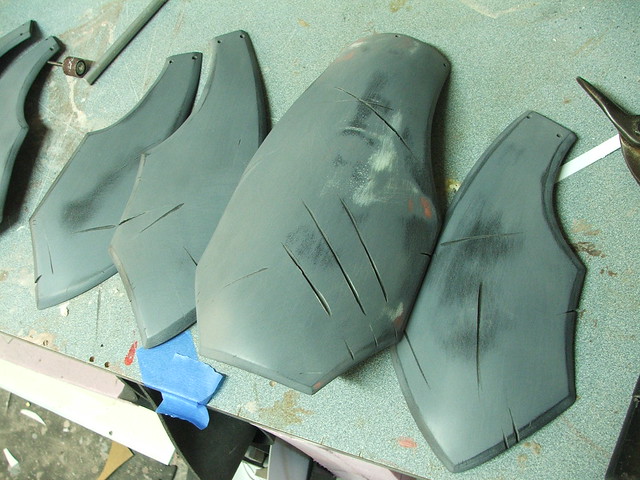
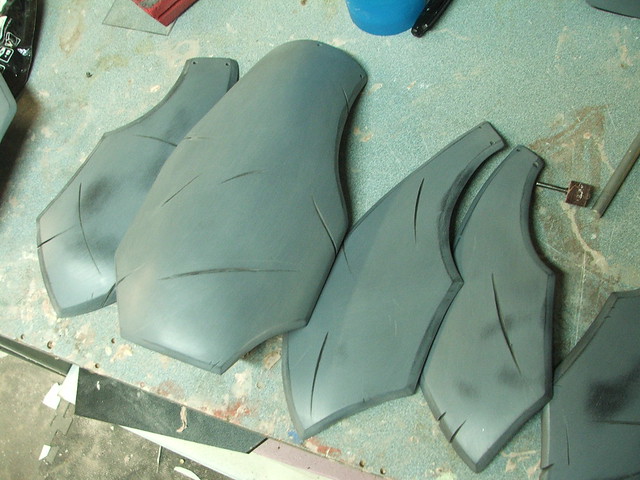
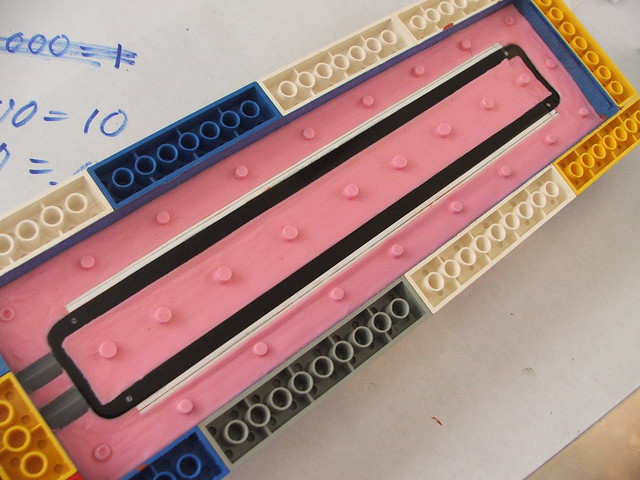
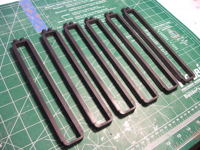
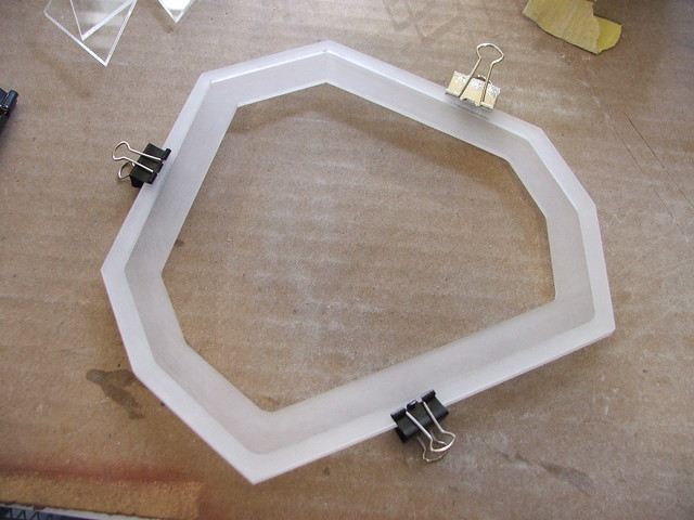
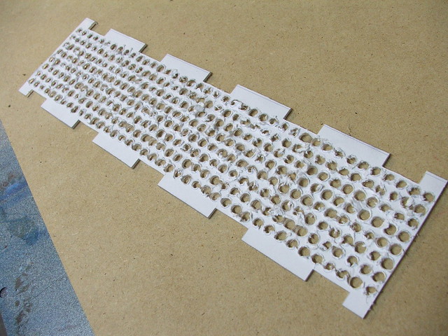
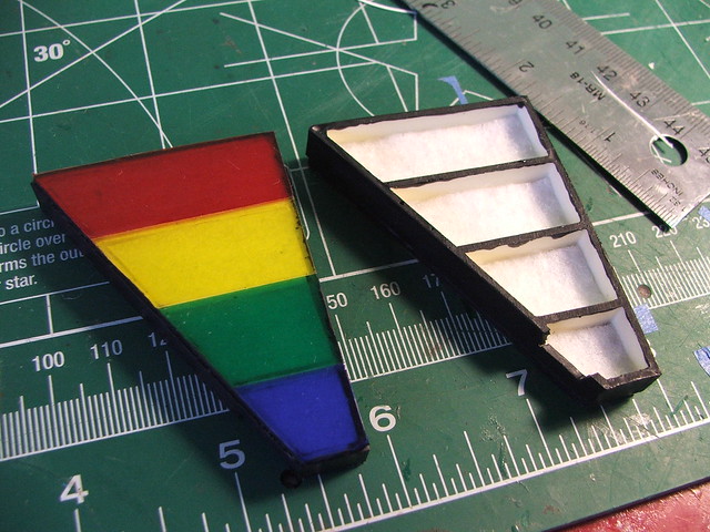
Sintra is a foamed sheet of PVC plastic, and it doesn’t really like to take compound curves very well. A lot of work went into heating specific parts of the material, bending them to shape, re-heating, and repeating. There were several test fits to make sure the curve of each piece worked well with the parts next to it. The shot below shows the parts about halfway done with this process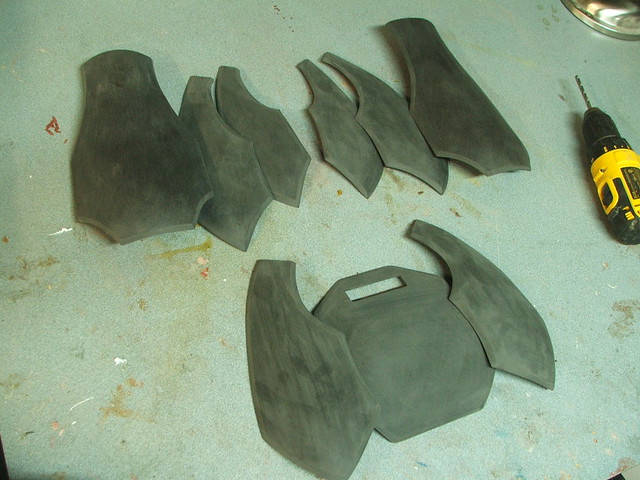 After the curves were finalized, each piece was sanded to remove the texture of the sintra, then given a coat of primer and light filler where needed. These parts got a lot of damage and weathering, done mostly with a dremel tool and engraving chisel. The small holes at the top of the plates are for stitching into the Claymore top shirt part later.
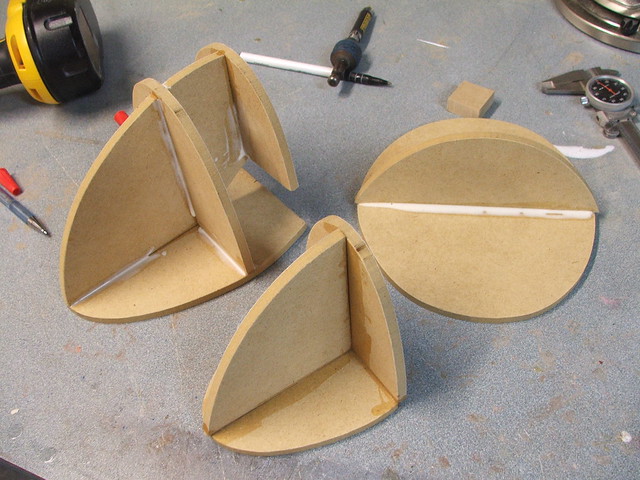
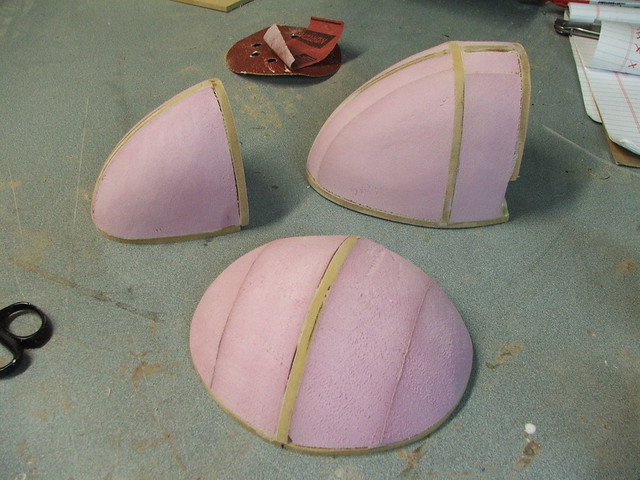
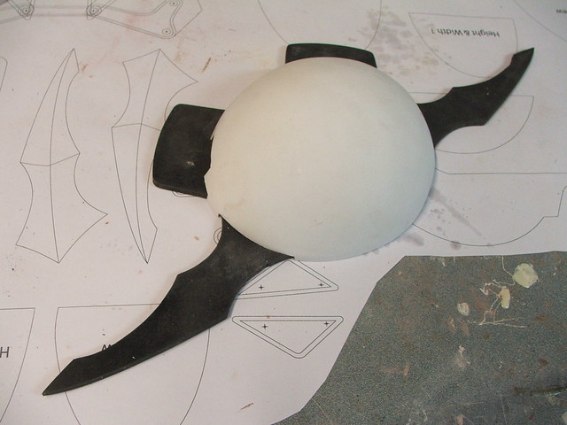
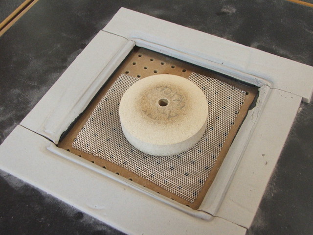
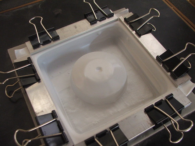
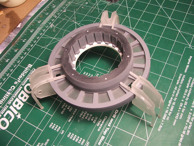
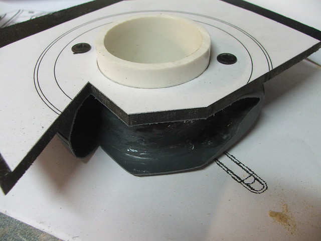
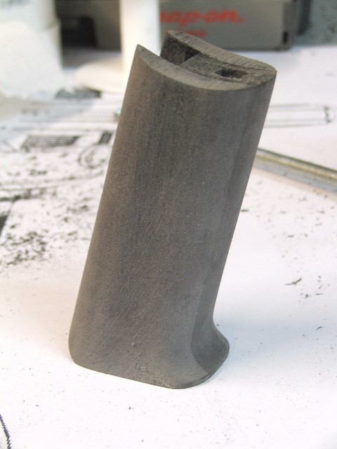
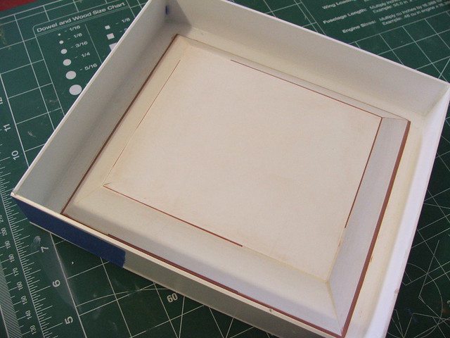
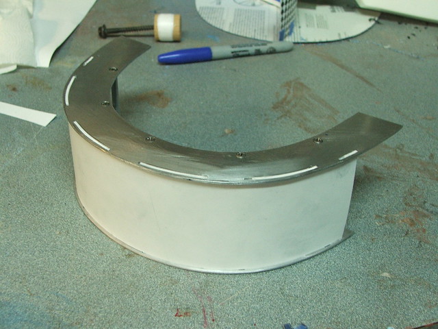
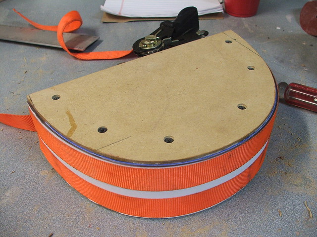
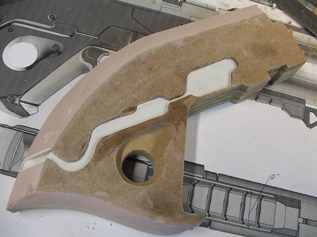
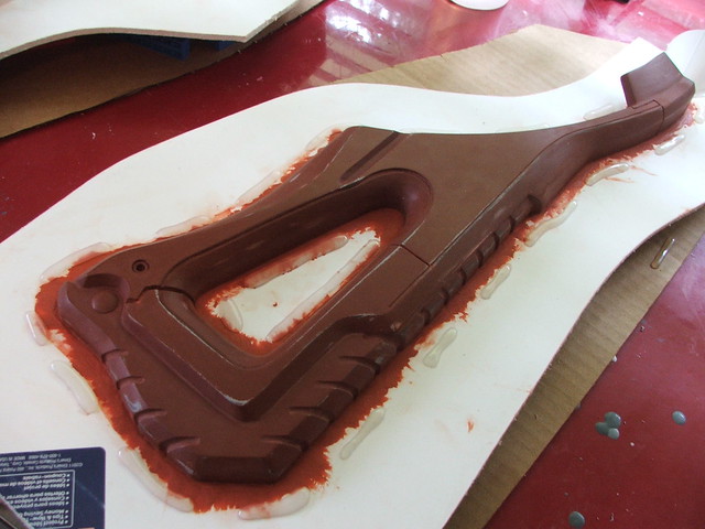
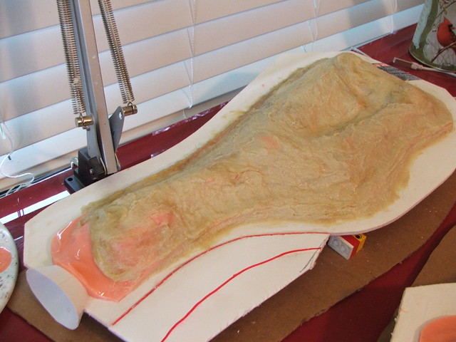
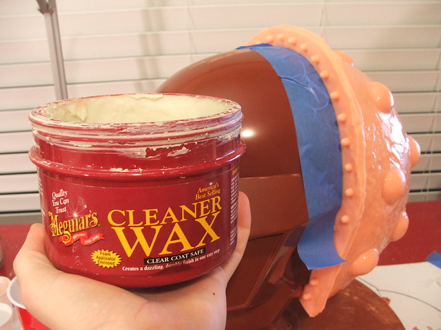
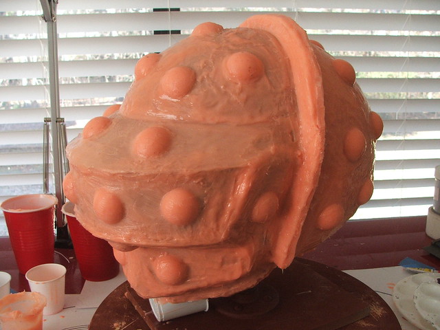
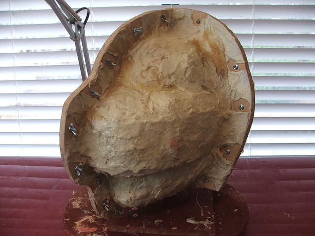
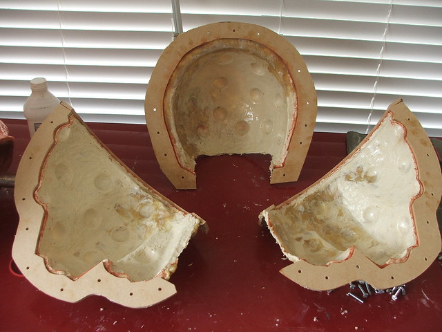
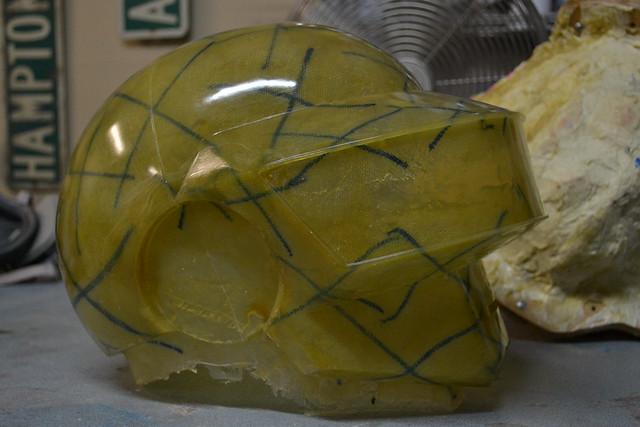
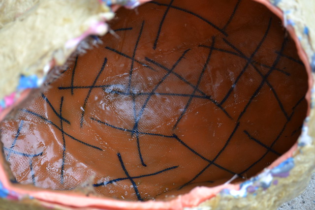
Here’s where we get into somewhat unfamiliar territory where I’ve just decided to wing it. If you’ve never seen a process like this before, its probably because I had no clue what I was doing and just felt like making it up as I went along. There are better ways to do things like the below, I’m sure, but since the project budget couldn’t include pricier materials to do proper lifecasting, this seemed like a pretty good budget minded alternative.Claymores have 2-part greaves which cover their calf, shin, ankle and the upper part of their foot. I started off by making a set of packing tape molds of Cathy’s legs. These started out as trashbags wrapped around the area to be molded, then wrapped tightly with tape and cut along a seam when finished.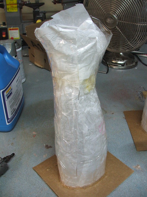
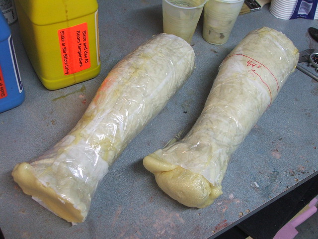
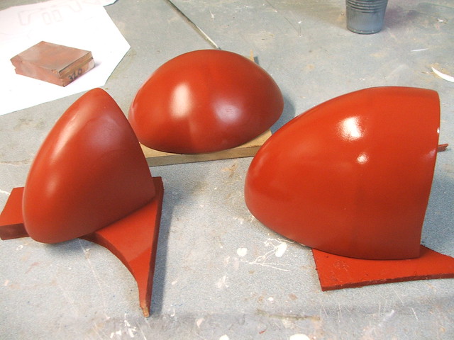
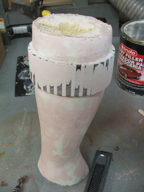
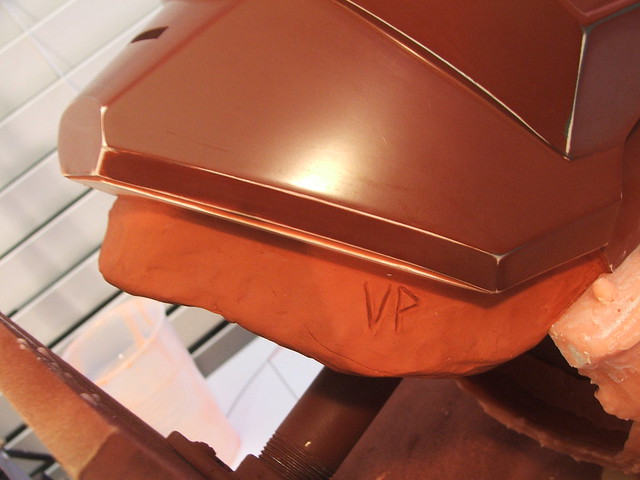
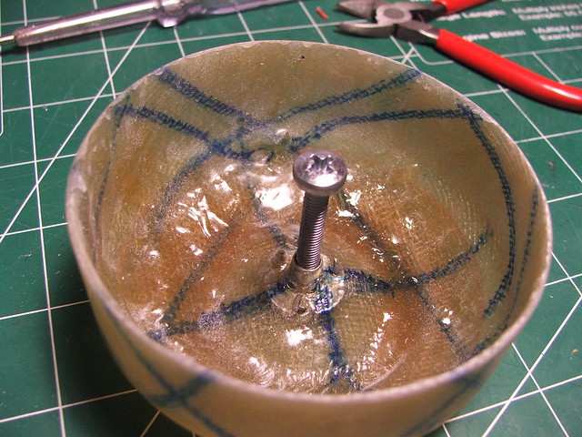
After removing the tape, I skimmed the outer sections of the foam with bondo to make a smooth surface the same shape as the greaves.
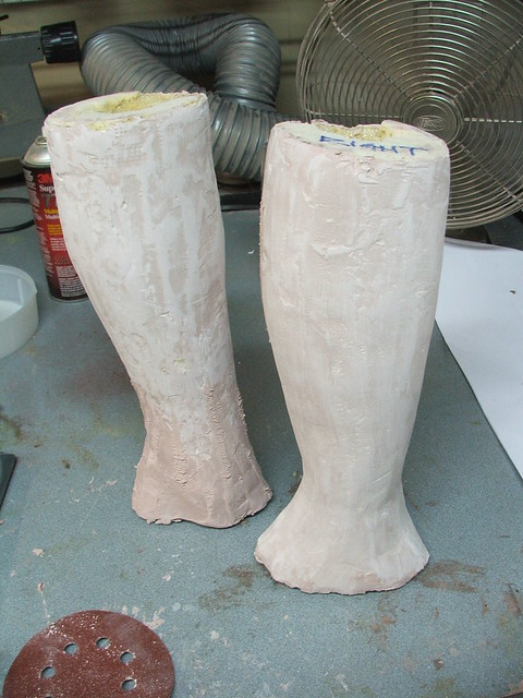
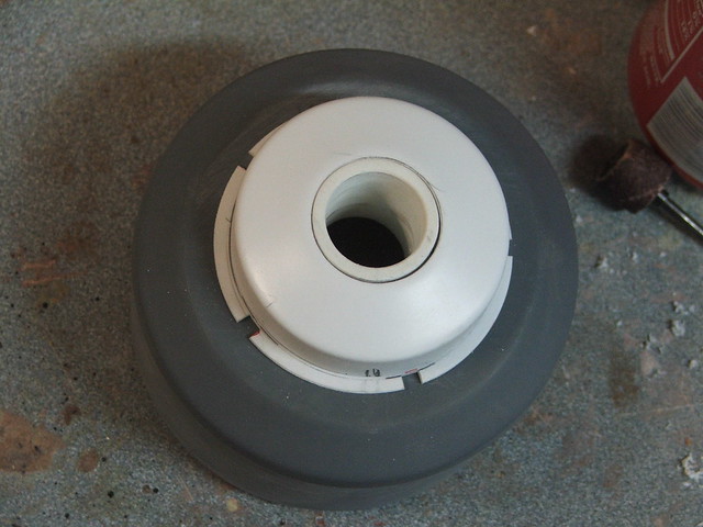
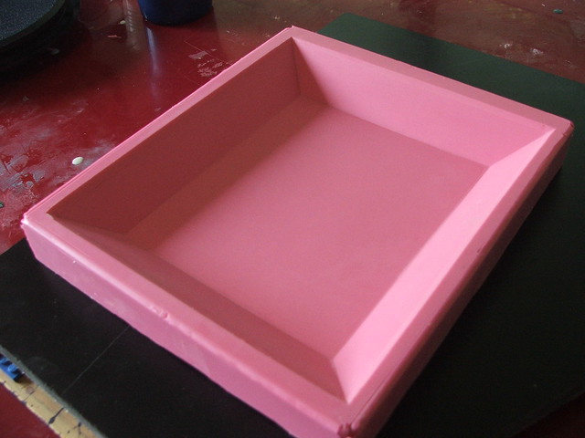
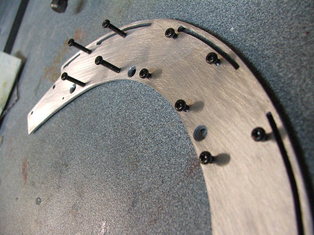
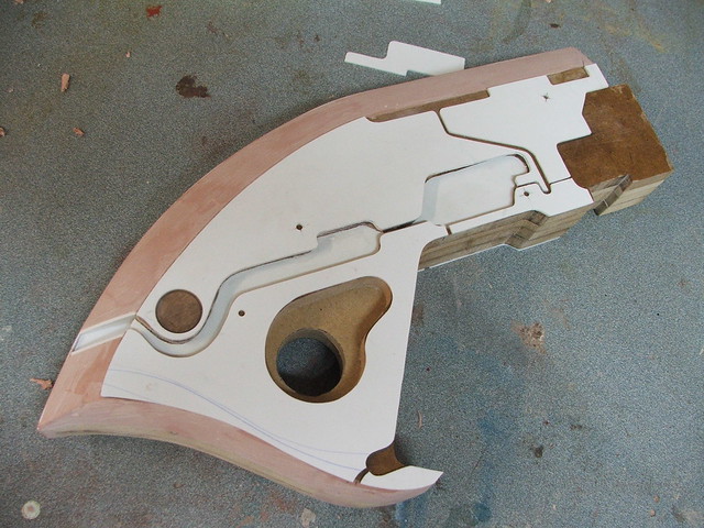
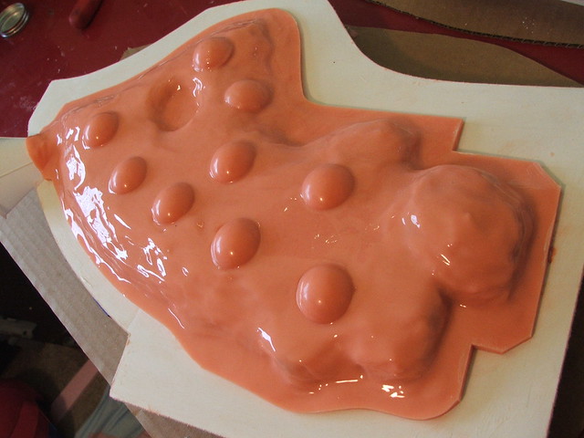
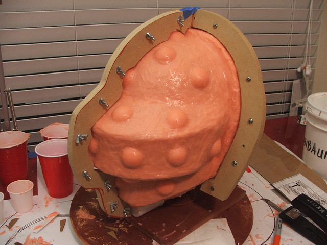
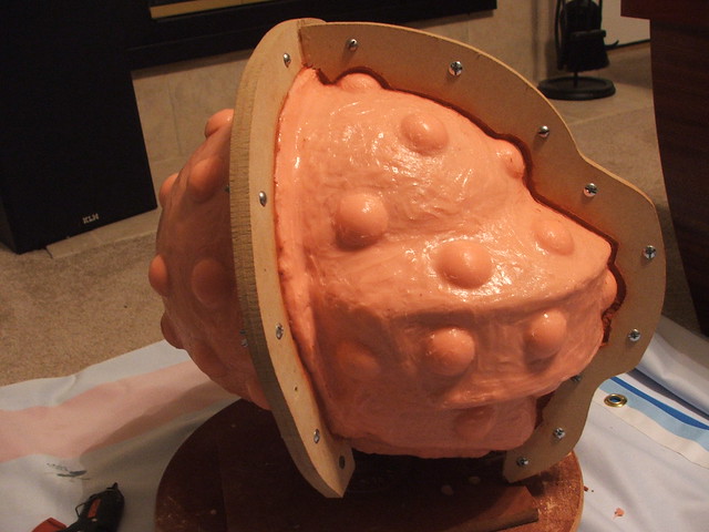
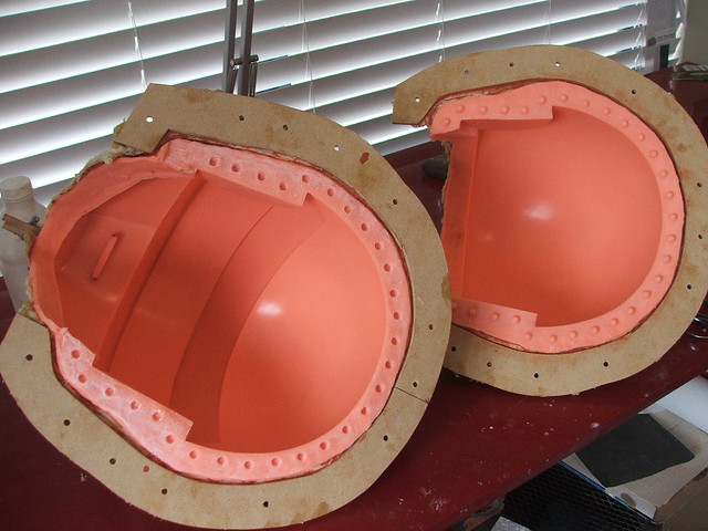
There’s a large cuff at the top of each of the greaves, which has a long spike leading up to it. In order to make sure I had a uniform shape and thickness around the entire perimeter of the leg, I cut strips of sintra out and glued them to the bondo around a mark on the upper part of the calf. The gaps between the strips were blended in with bondo.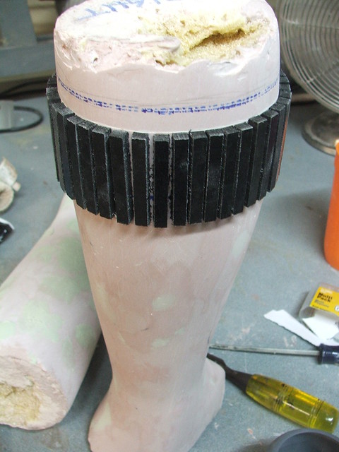
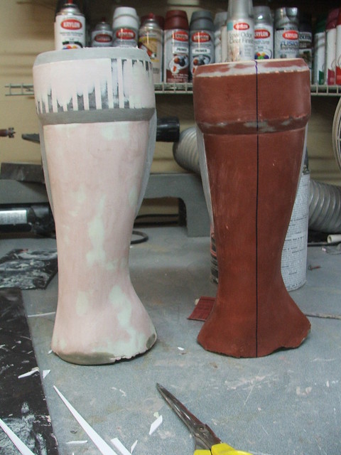
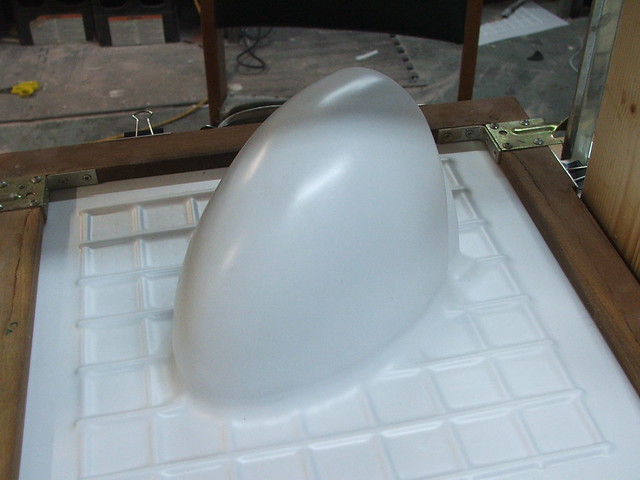
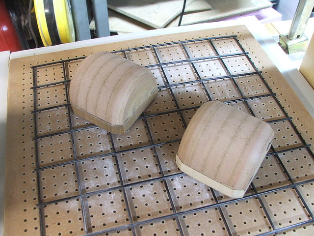
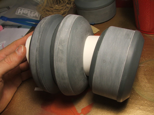
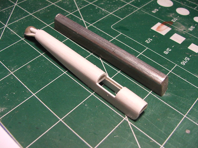
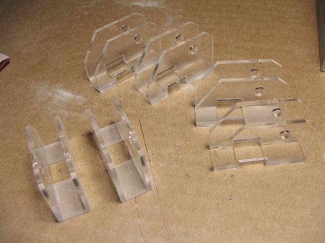
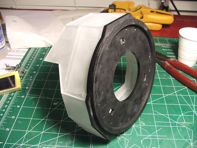
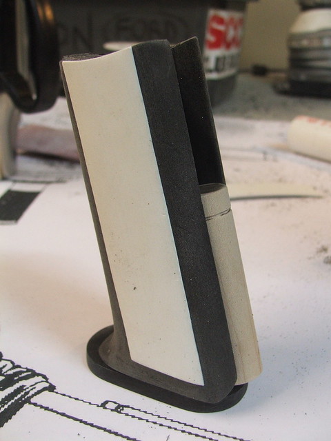
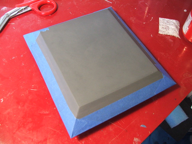
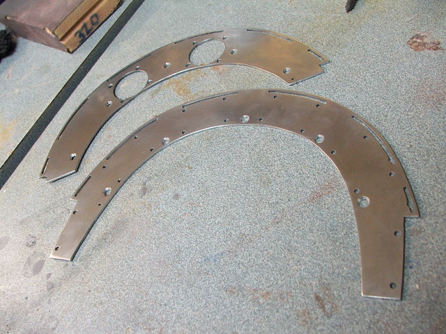
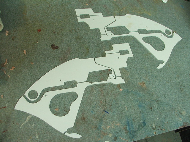
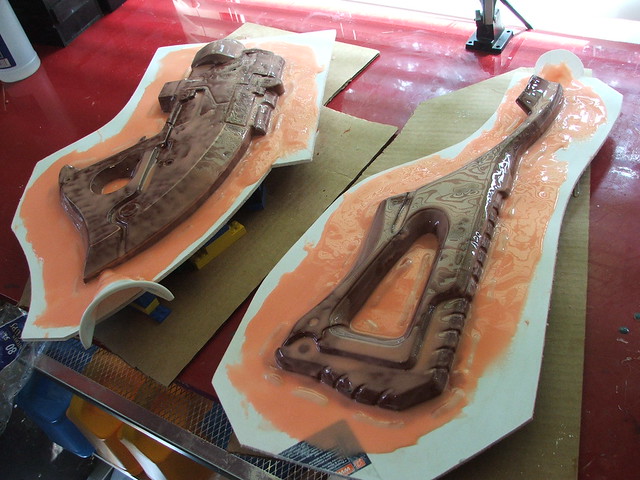
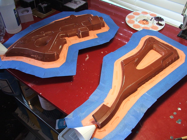
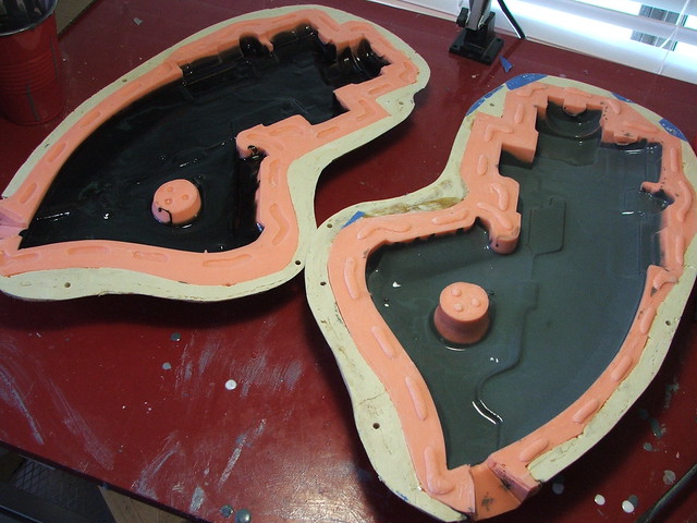
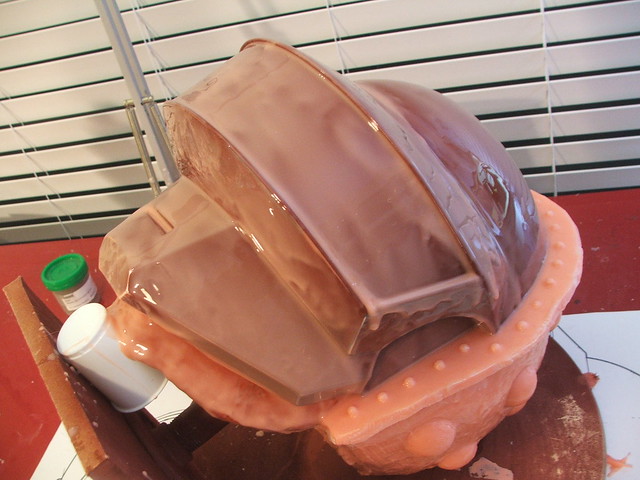
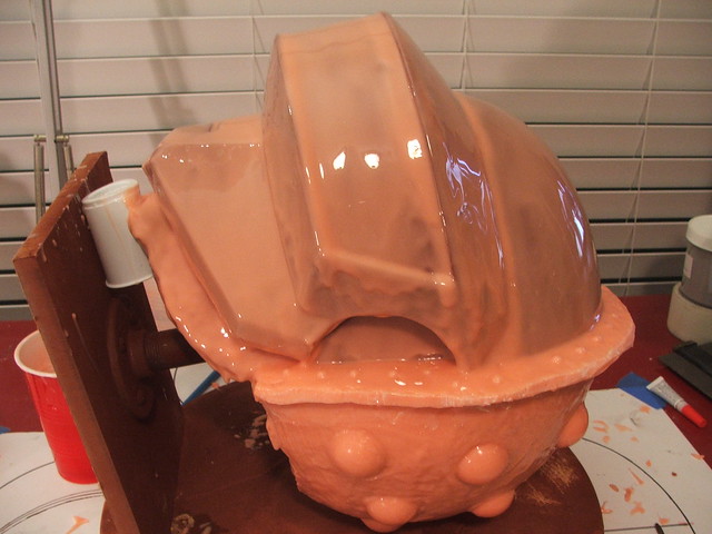
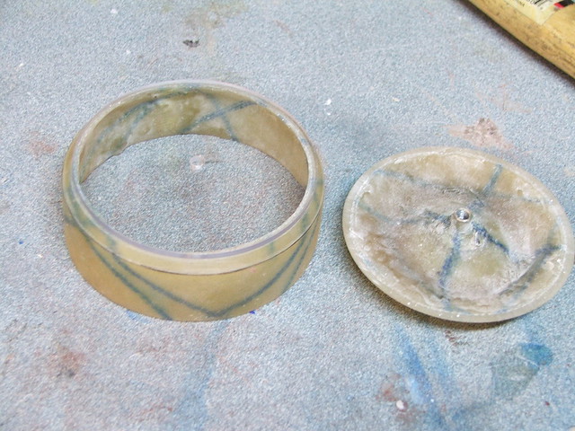
These parts were cut in half on a bandsaw, then glued to 1/2″ MDF risers in order to make vacuumforming bucks. In the shot below, you can see a proof-of-theory pull from some thin sheet I had laying around.
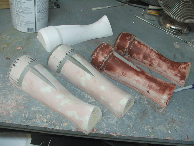
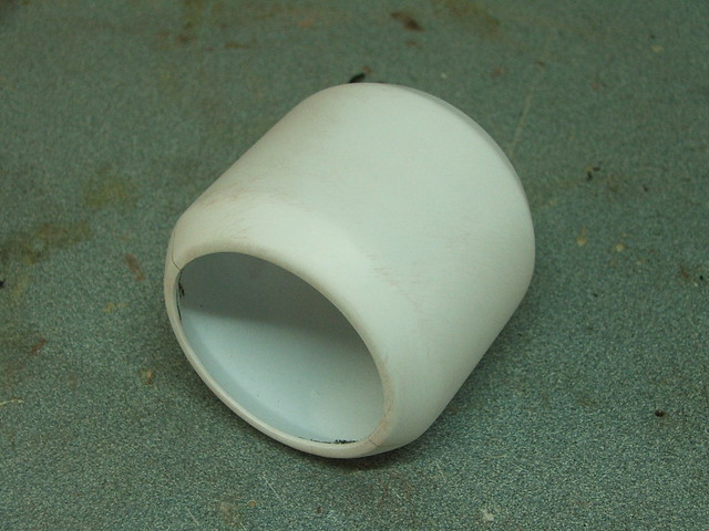
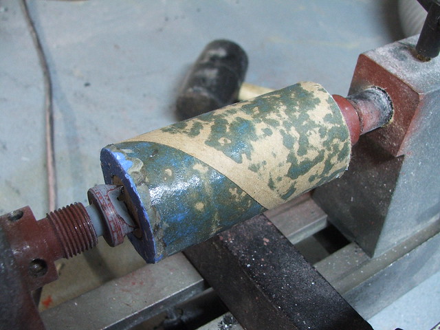
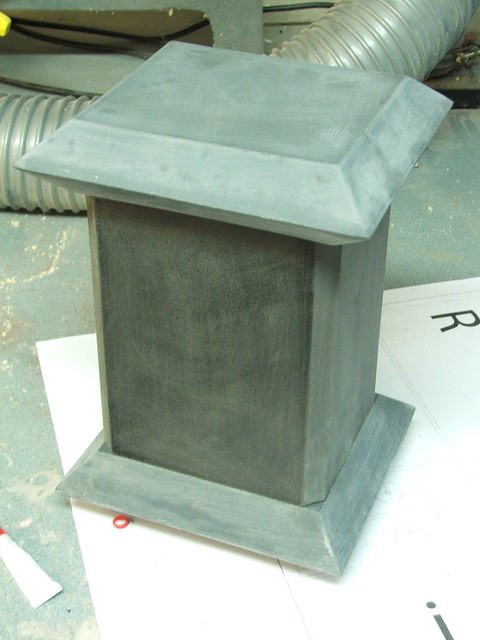
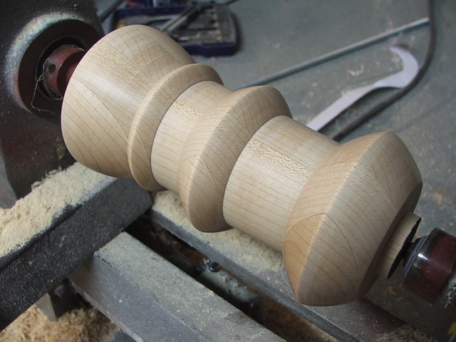
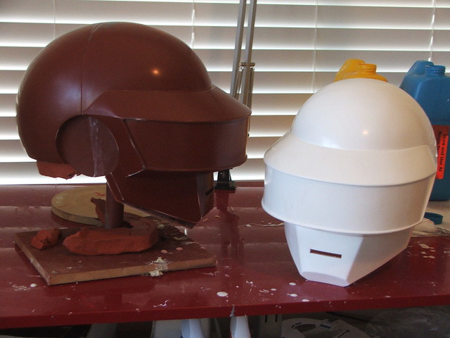
The completed master, next to a part pulled from .10″ styrene!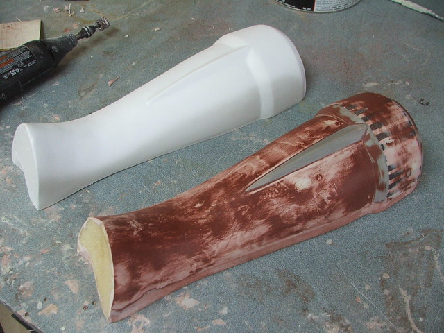 The last task for my vacformer was to make the wrist cuff. This was lathed out of some laminated sheets of MDF then pulled in .10″ styrene and glued into one part. Shockingly, Cathy’s hand fits through this tiny part with room to spare!
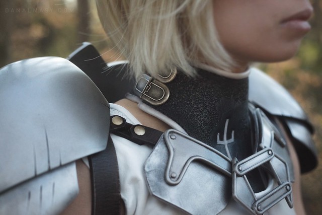
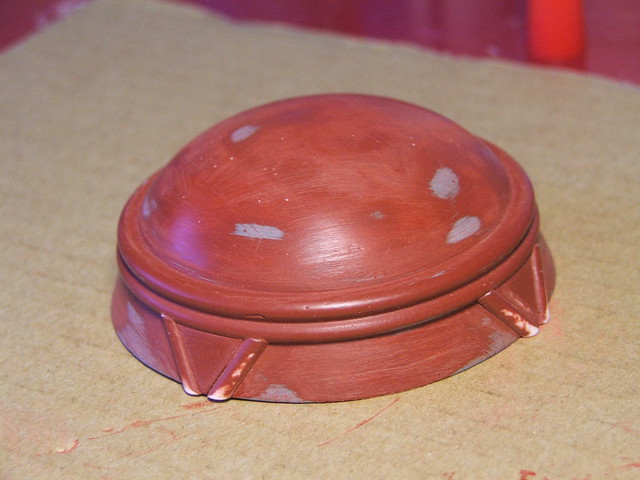
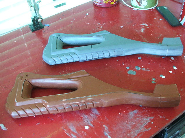
At some point I started to get behind on deadlines, and my documentation suffered a bit as a consequence. These clasp parts over the chest are an assemblage of styrene sheet and half round styrene bar stock. Aside from this, I don’t have any shots of their creation. Sorry!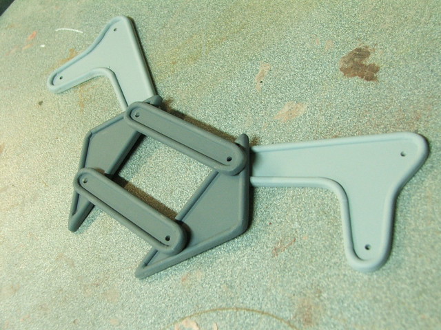 After everything was primed and prepped (my preferred method is going over the primer with a 320 grit sanding sponge and diluted surface cleaner like windex) each part got a topcoat of silver before weathering.
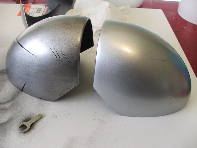
Weathering these parts made a huge difference in their realism! I used airbrushed acrylics, then topcoated each part with gloss clear in order to seal in the “grit and grime.”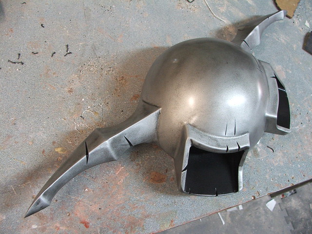 The two shots below show the difference between a fresh coat of paint and a weathered surface. The differences in parts like the greaves are subtle, but it really helps the overall look, in my opinion.
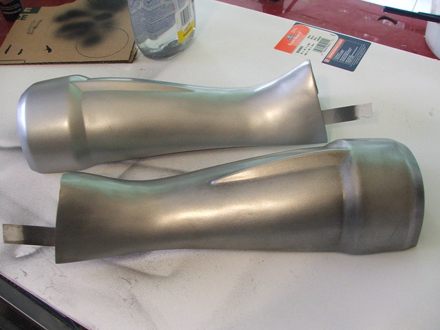
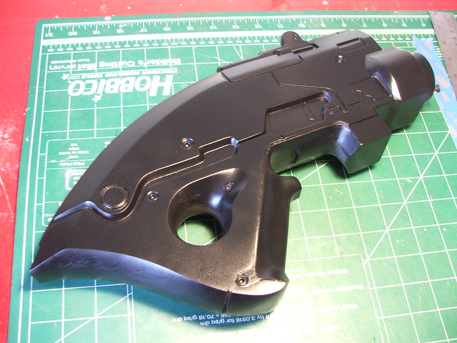
The greave and boot parts on one of the shoes for a mockup. After I gave these parts to Cathy, they got a velcro strip along the inside edge to keep them together and hide the side seam a little better than in this pic.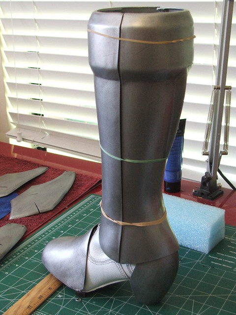 The final bit of weathering was the spattering of Yoma blood on a few various parts of armor. The blood itself is done in acrylics, and like the rest of the weathering, sealed under a coat of gloss clear.
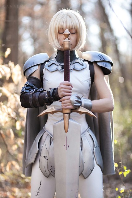
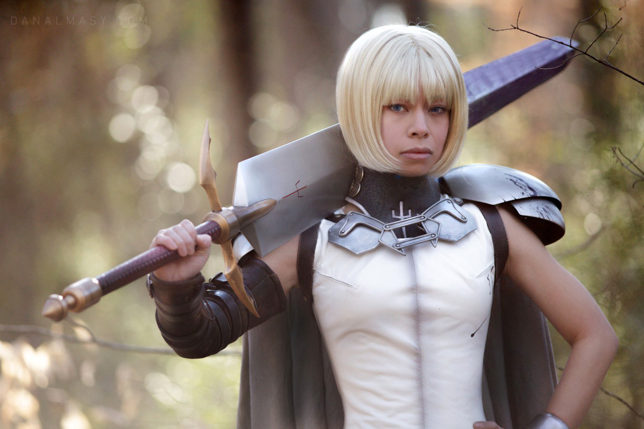
The final pieces all assembled with Cathy’s lovely costume work (see more of her stuff at God Save The Queen Fashions!) and shot by our friend and awesome photographer, Dan Almasy:


 Really wish I’d gotten a shot of this part being made. Another vacformed part – the hand armor!
Along with the weathering on the armor, I also helped out Cathy by adding some blood spattering and weathered grime to her cape. Remember: dirt adds realism.
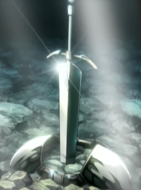
Clare’s Sword, Claymore
As part of another joint costume adventure between myself and my friend Cathy over at God Save the Queen Fashions (some readers may recall her work on the Daft Punk leather ensemble) I was drafted to create the sword and armor for Clare, the protagonist in the series Claymore. Aptly named, the Claymores carry giant swords almost as tall as their wielders – which they’re able to fling around one-handed with ease. I needed to make something as lightweight as possible, but still able to handle the rigors of convention use.
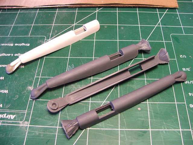
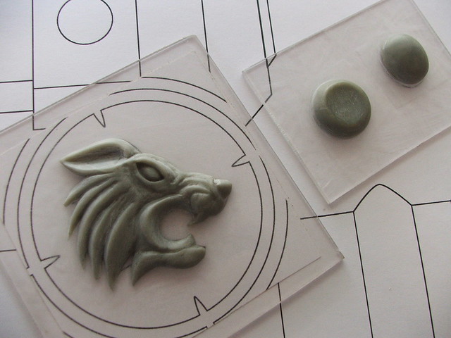
There are a lot of variations of these blades around. Specifically, the difference between the swords the collectable figures hold (lower two) and those more accurate to scenes from the series (top) I didn’t check the manga; chances are there’s a myriad of other variants there as well. Cathy and I decided to go with the top option.

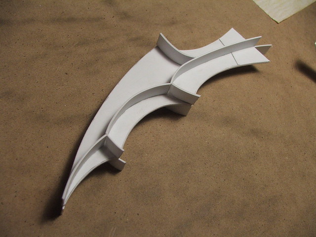
The first part of this build started with the hilt “wings.” These started as a piece of styrene patterned to the same dimension as the profile of one wing.
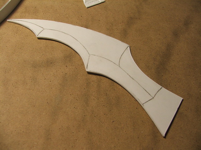
I added styrene “dams” to this, and used these sections to mark off where the upper ridges should be. By filling the areas in with apoxie sculpt and sanding to shape, I knew exactly where the lines on the part should peak.
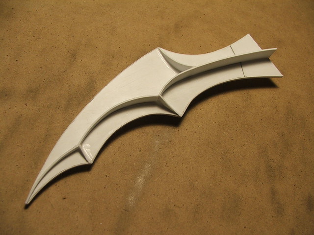
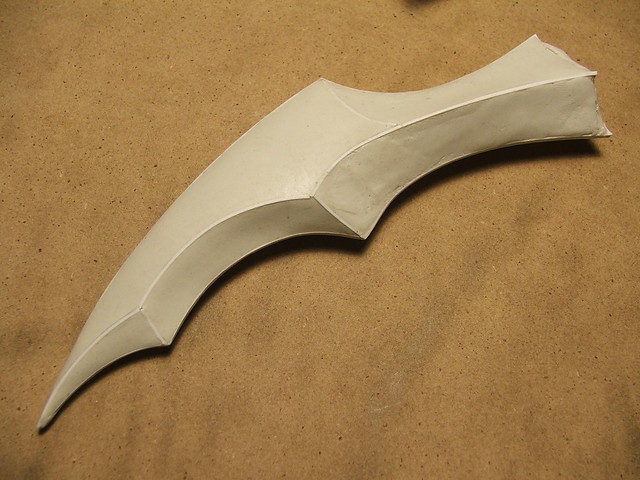
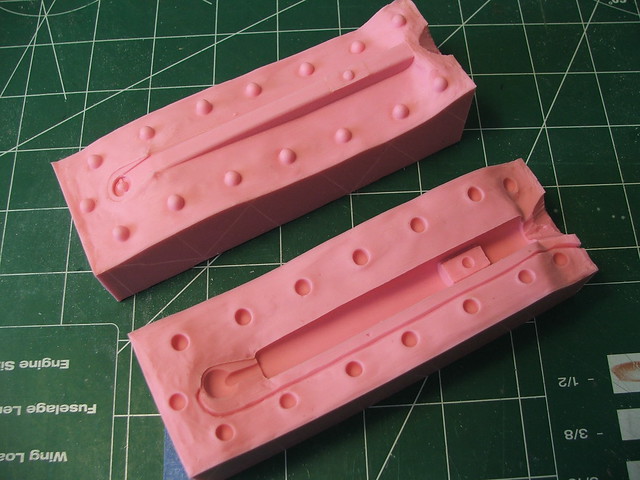
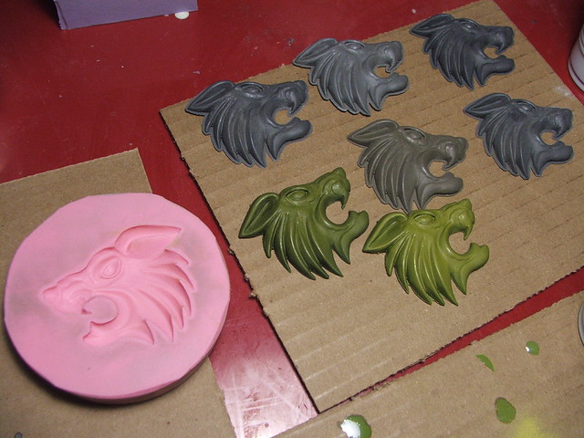
A little bit of sanding later, and this part was put under silicone rubber to mold and make an identical copy. The silicone used here is Smooth-On’s Oomoo rubber. I only needed a couple pulls, so mold longevity wasn’t an issue.

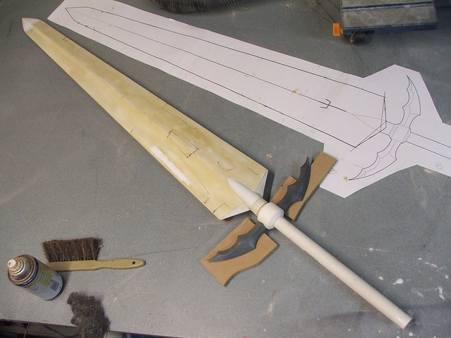
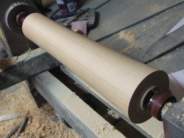
While this was setting up, I started work on the giant blade portion. I needed things to be light, but still rigid enough to be handled for several hours. The central spine and handle of the entire piece is a PVC pipe with an oak dowel embedded down its entire length.
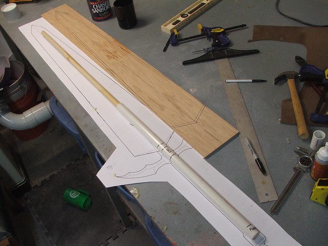
This spine was extended to the width of the blade by cutting a set of 1/4″ thick oak boards to act as lateral reinforcement. These were first zip tied to the blade to glue them into place…
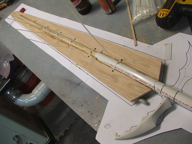
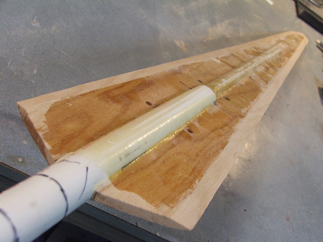
…and after the glue dried, the board was fiberglassed onto the center wooden dowel using 2 layers of glass fiber cloth and polyester resin. I also beveled the edge in order to get this center spine to fit better around the blade “sleeve” which I created in the next step.
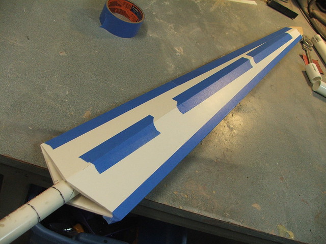
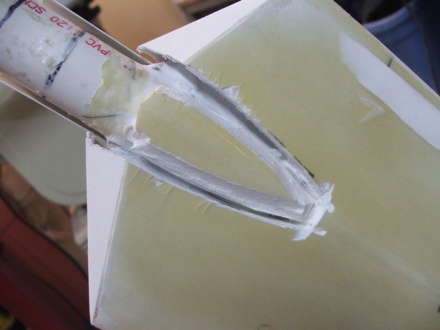
For the exterior of the blade, I trimmed two long sheets of foamcore into wedges and shaved a V-shaped notch into their center, as well as tapering the outer edges. This will make more sense shortly, I promise.

After taping up the seams and slipping the foamcoare blade sleeve over the wooden spine, the basic form starts to take shape!
This was affixed to the wooden spine by slush casting Smooth Cast 300 into the cavity at the back of the sword. At this point, the whole assembly weighs about 2.5lbs.
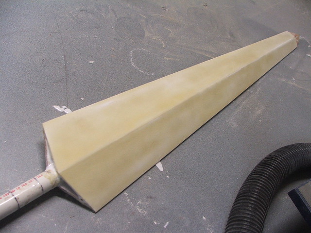
To strengthen this outer skin, I brushed polyester resin over the foamcore shell. In retrospect, epoxy resin would have been a better idea, since the polyester soaked through the paper outer section on the foamcore and dissolved the foam underneath, necessitating cleanup later on in the project. Live and learn…
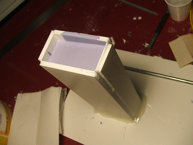
The tip of the blade was an exercise in weird technique. I knew this had to be very robust part of the sword, since the most likely pose with a 5-foot-tall blade will be holding it upright with the tip set on the ground. I made a small box out of cardboard, set it around the blade end, and filled it with Smooth Cast 300 resin.
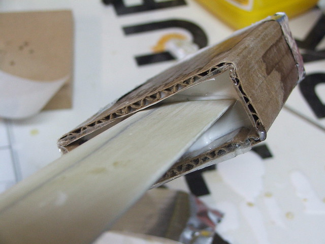
It took a long time to get from there to here, spent mostly on my belt sander, but the end result was a solid resin tip. Rigid and definitely the strongest part of the blade.
The open edges at the back were covered with styrene plates

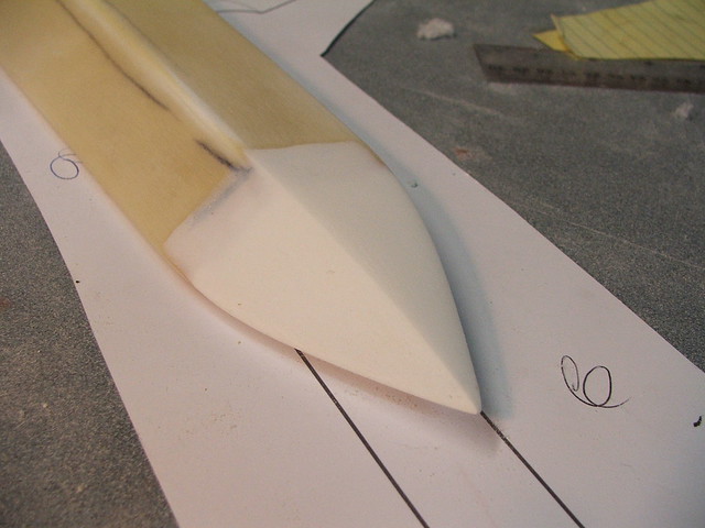
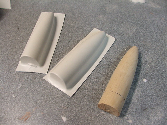
To make the pointed tip that leads up to the cross guard, I lathed a bullet shape out of a poplar dowel, then vacuumformed a couple of copies in styrene.
Getting these in place required a bit of hackery to the shaped outer blade section in order to get them to fit….
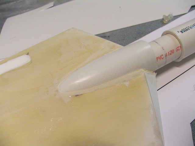
But after adding a bit of epoxy resin as filler (learned my lesson from the polyester from before!) The shape was blended back into place.
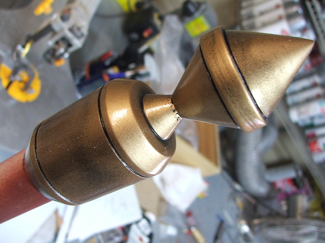
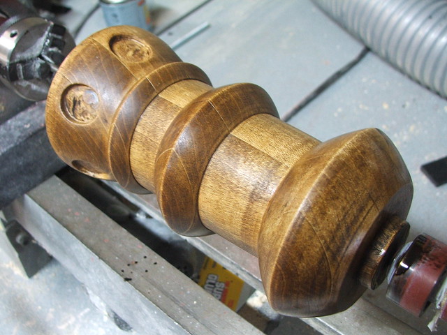
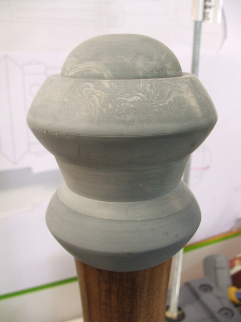
The cross guard and pommel sections were lathed from blocks of urethane casting resin. Blanks were created by filling cardboard tubes and allowing them to cure.
After some time with the lathe, the following parts emerged: Pommel…

…and cross guard sleeve.
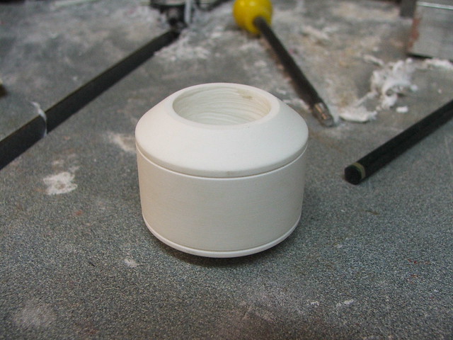
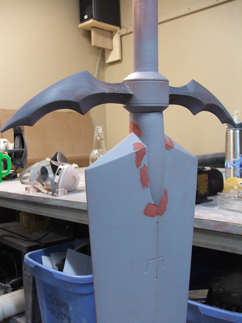
Quick mock-up before primer
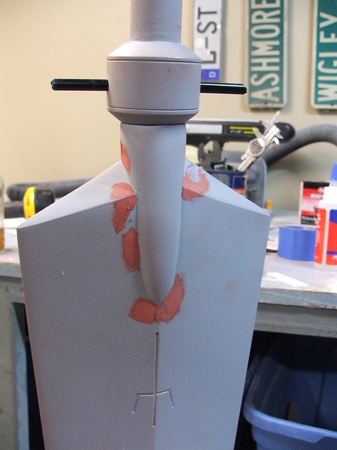
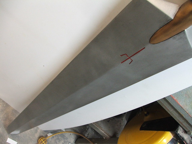
Clare’s insignia was carved into the blade with a dremel tool. Since this cut into the foam a bit, the cavity was carved deeper then filled in with urethane resin to make an even and level recess.
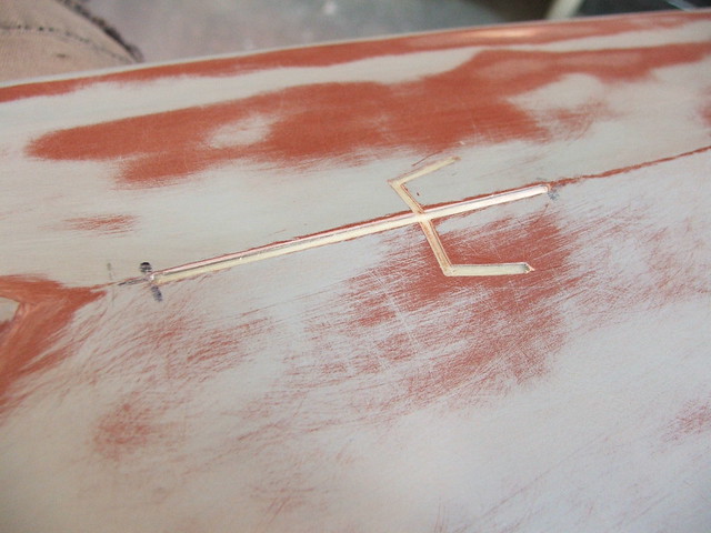
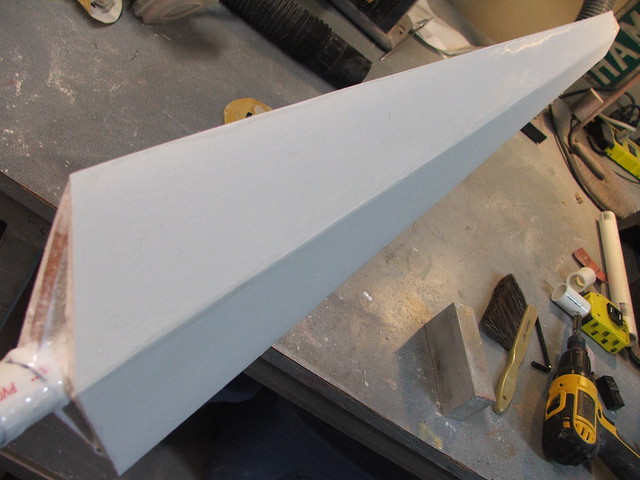
After a coat of primer, the shape is nearly ready for paint.

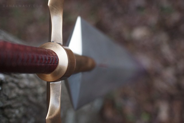
The wing sections on the crossguard are affixed to the blade handle with an ABS dowel that passes through the entire center spine. I wanted to make sure these were as stable as possible, as they might take a random hit now and again since they sit so far outside the width of the blade.
Finally, paint! The blade was coated with Krylon silver, and the hilt/crossguard was done with testor’s enamel. Lots of gloss clearcoat went over the weathering in order to keep the layer of grime and dirt intact.
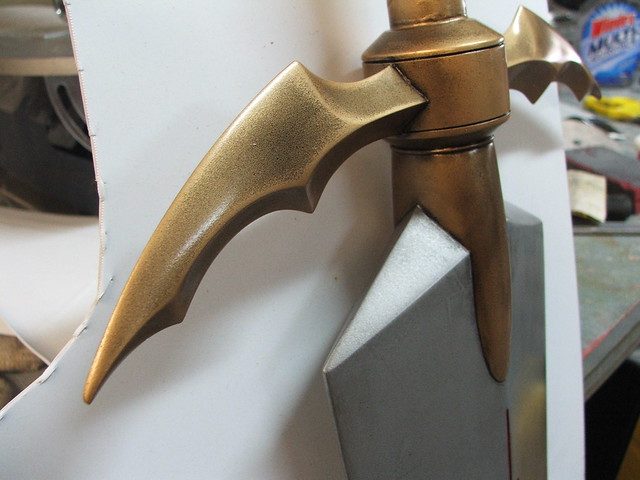
The final detail was a smattering of Yoma blood on the first 1/3 of the sword. If you’ve seen the anime, there’s a TON of blood flying around.
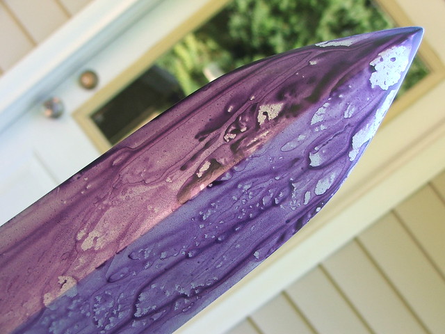
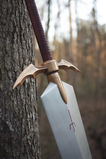
A few shots of the final piece, out in the elements, taken by my friend Dan Almasy. The leather handle wrap was done by Cathy after the sword was finished.

If you’re interested in the rest of the process behind the build on Clare’s armor, check out my write up on that project here.
More shots of the process are available on my Flickr stream for those interested in a little more background behind the build.
Thanks for reading!

Half Life 2: Gravity Gun
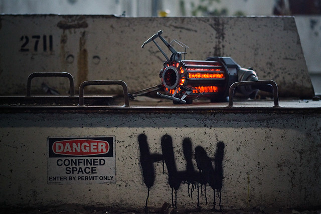
Last month I posted some pretty pictures of the finished Gravity Gun, taken by my good friend Dan Almasy. At that time, the gun was newly finished and on its way to the Child’s Play charity dinner in Seattle. I really had no idea what to expect this year – my Portal Gun sold last year for a whopping $14,500 – but its difficult to get a grasp on things when numbers start to reach a point like that. Was it a fluke, or is Portal just that big of a game?
For this year, I knew I had to keep up the momentum (or die trying!) A longstanding “someday” project of mine was the Gravity Gun from Half Life 2. I never had anyone actually commission one of these from me, so I decided the Child’s Play auction would be the perfect place to release it. It sold for a staggering $21,000 – and here’s how I made it.
Well, first, this is possibly the longest entry I’ve ever written. That’s really saying something considering the length of some of my other write-ups, but I felt a warning should be in order. Get a cup of coffee and a comfy chair; its gonna be a while.
Alternatively, if you’re like me and “patience” isn’t something you’ve got in abundance, then please enjoy this less-than-two-minutes video of the finished product.
Onto the build!
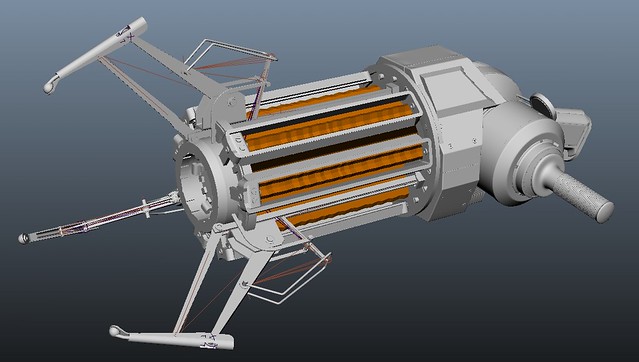
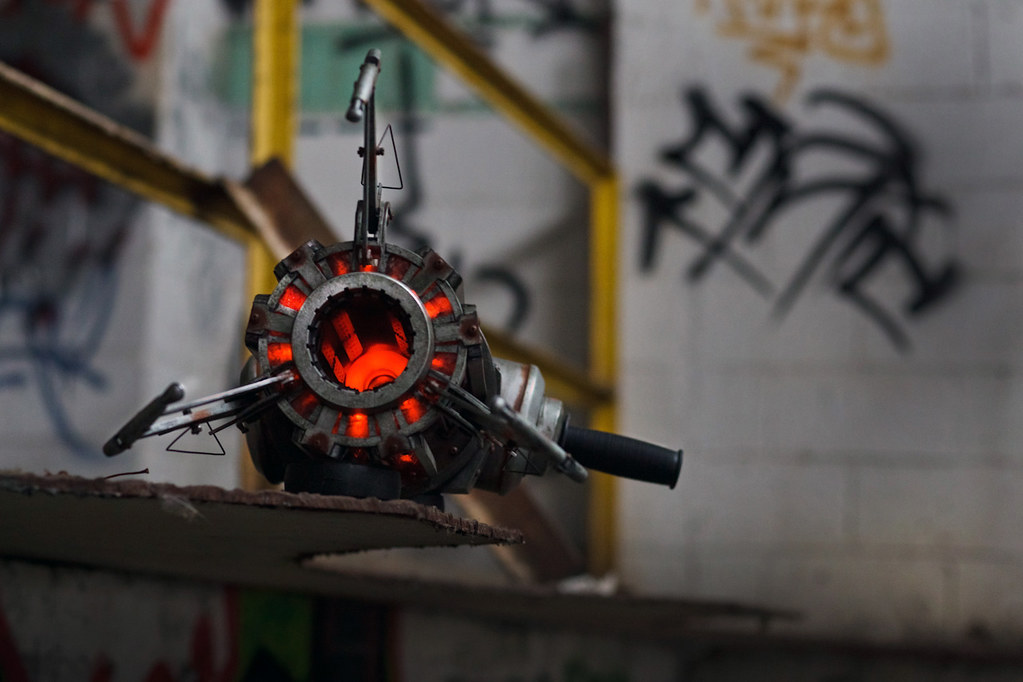
The biggest problem with the Gravity Gun is the somewhat incomplete reference of the piece. The in-hand model only shows 3/4 of the backside, and the world model is woefully low resolution.
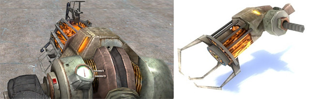
As luck would have it, when I brought the Portal Gun to the dinner last year, the guys at VALVe offered a tour of their facilities. While I was there, I met one of their designers named Tristan Reidford who had been working on his own very detailed model of the Gravity Gun. He gave me a copy of the files to work with, and now I had the best blueprints I could possibly hope for!
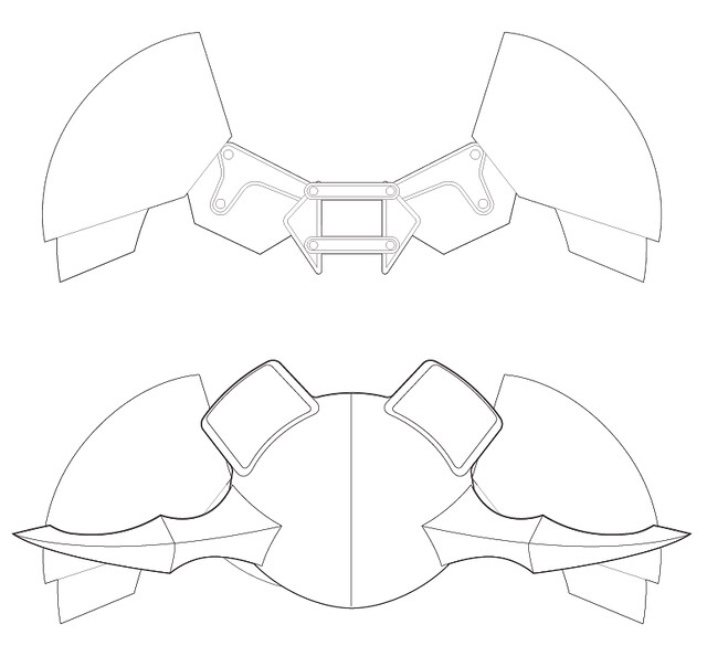
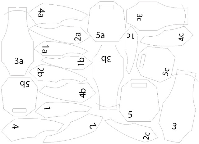
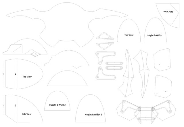
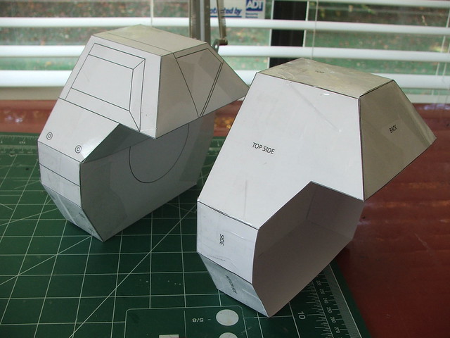
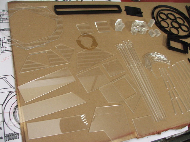
This project marks my first foray into the world of laser cutting. A lot of the geometry needed to be exact, so I spent about 4 days working out all the project parts in Illustrator. Parts were all cut by Ponoko, in various thicknesses of acrylic. Before I sent the files out though, I made paper templates to make sure all my designs were accurate. Below are two mockups of the main gun body – both were slightly off, so its a good thing I made mockups before committing!
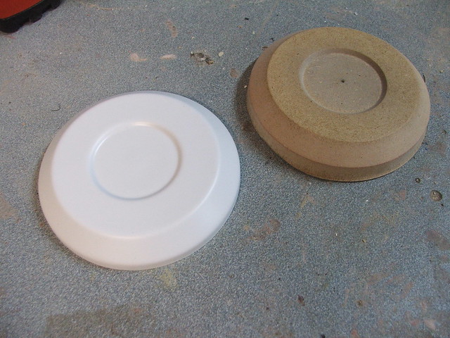
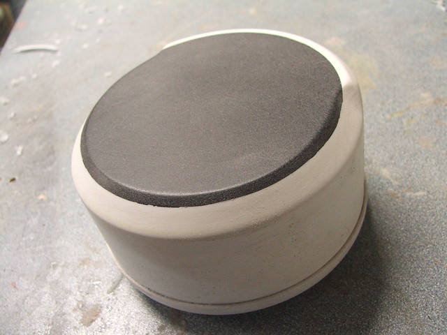
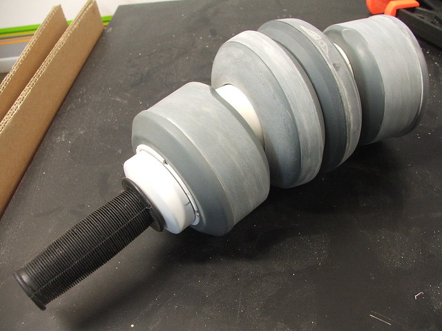
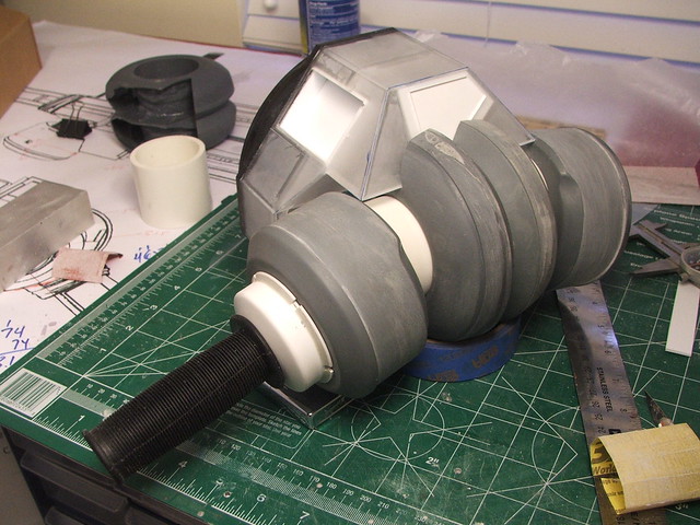
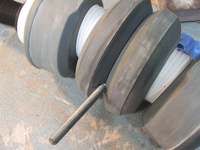
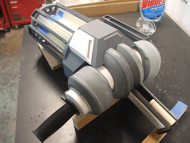
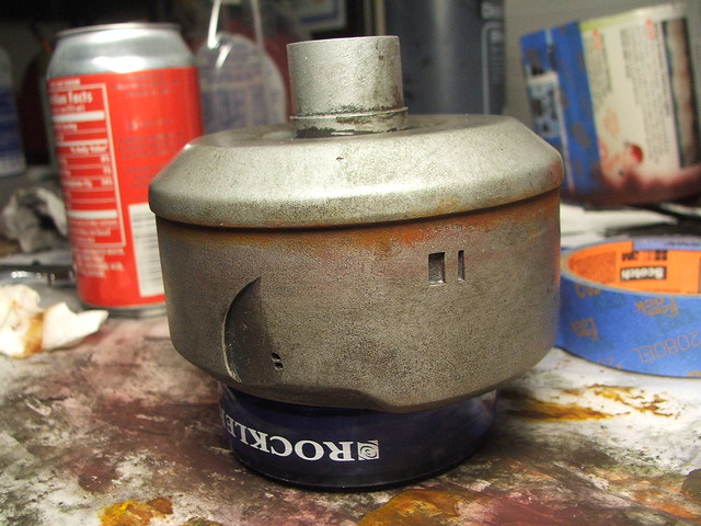
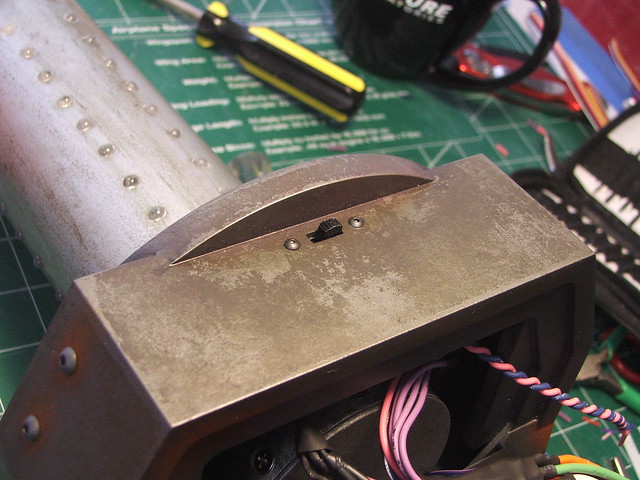
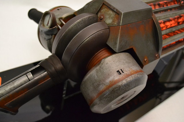
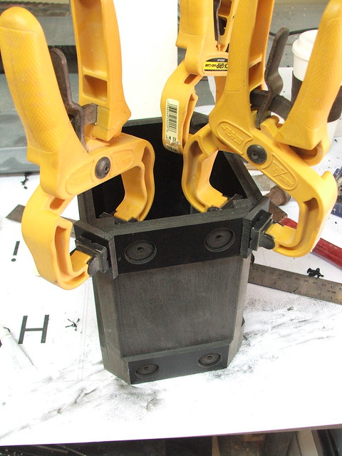
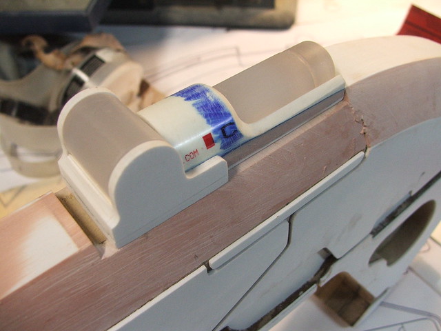
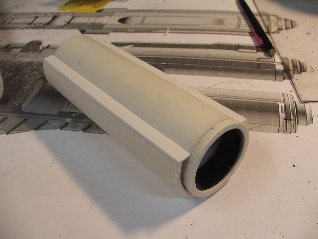
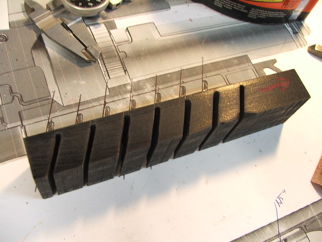
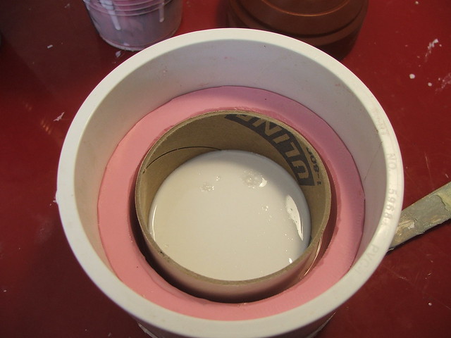
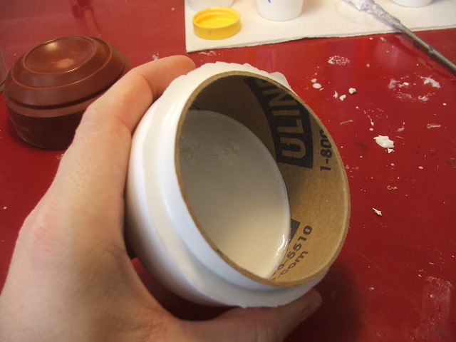
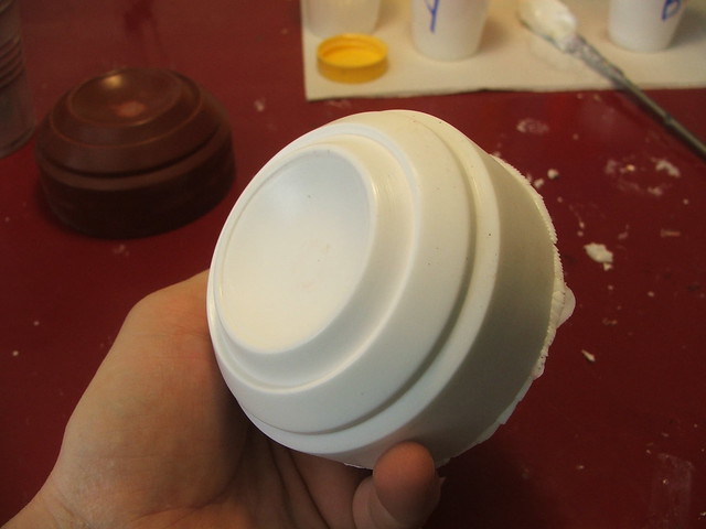
While waiting for the laser cut parts to arrive, I started work on the handle portion of the gun. I started calling the cylinders toward the back the “drum assemblies” as I had absolutely no idea what they were supposed to be. Both would be molded then cast in resin. I started the smaller drum by vacuumforming the outer “cap”
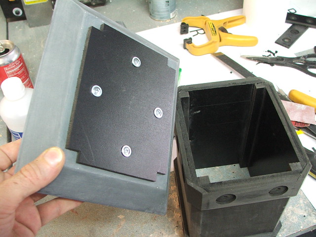
The rest of this part was a hodge-podge of PVC and Sintra, beveled on my router for the funky edge along the inner section.
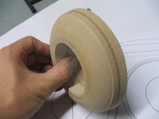
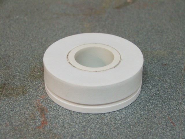
The inner drums were easier. Just lathe some MDF and cut out the middle on the scrollsaw.
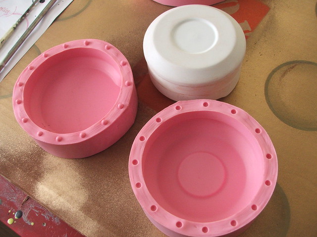
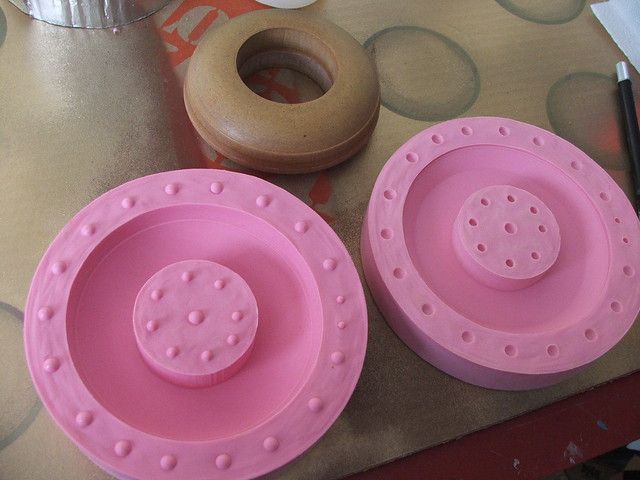
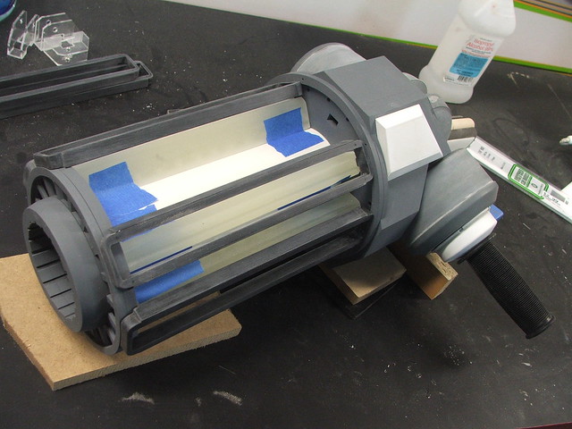
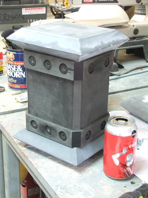
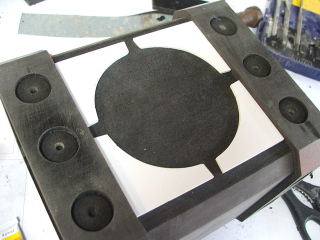
Everything molded and parts pulled! These were molded in Smooth-On‘s Mold Max 30 and cast in Smooth Cast 320 resin. Took a little practice to get the parts hollow with a uniform thickness.
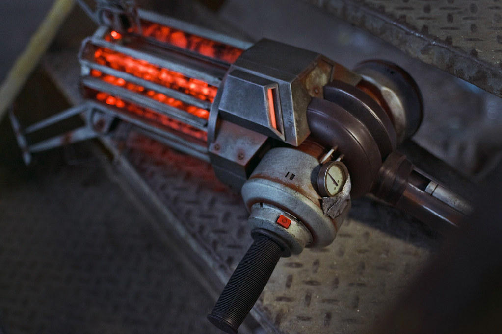
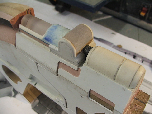
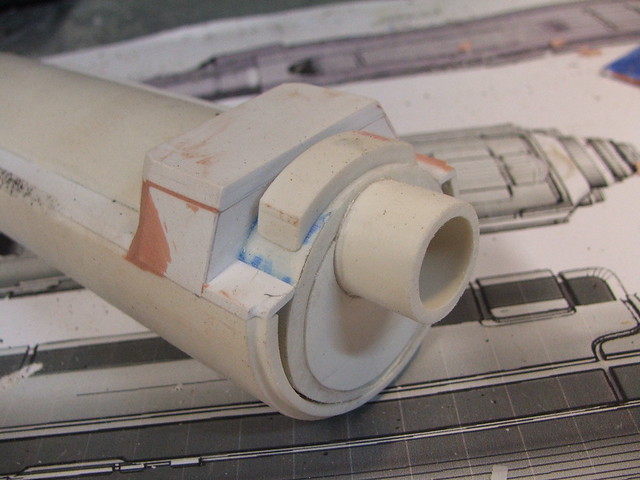
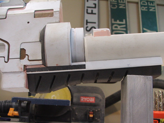
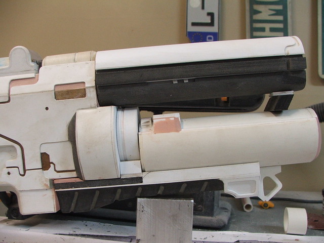
A few more details were needed for the handle area. The endcap was turned from MDF then vacuumformed like the larger drum cap, then set over a .75″ PVC connector.
The .75″ connector allowed me to make the handle removable in order to ship the thing. That bike handle was a pain to track down. In the end I bought 4 of them in case I ever repeat this project so I don’t have to go searching again – they’re an odd length, somewhere between an adult and a child’s sized handle grip. eBay to the rescue! All of these parts are mounted on a piece of 2″ PVC to get the angle and spacing of the elements correct.
At this point I still had some time to kill before the laser cut acrylic was delivered, so I set about making the prong-claw ends. The pic below is a vacuumform master (right) I used to make the curved shape of the prongs with in styrene. The rest of the shape was done with apoxie sculpt, some half round stock, and a 3/8″ OD washer.
I didn’t want to have to repeat that nonsense three times, so I made another mold. I’m pretty proud of this one, since I don’t usually cast parts this small. These came out perfect!
The next day, these showed up:
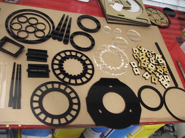
Hoooooooly crap, I had a lot of work to do. This was about 2 weeks before the auction deadline, too.
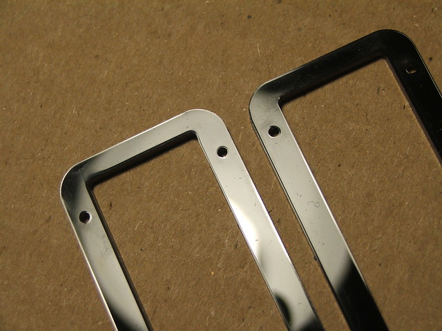
When designing the parts, I made 1/16″ holes in parts that were supposed to be joined together. The idea was that I would insert steel pins into these to act as guide holes and keep everything aligned during assembly. The parts below are the long rectangular brackets that sit above the glowing Xen crystals along the body of the gun.
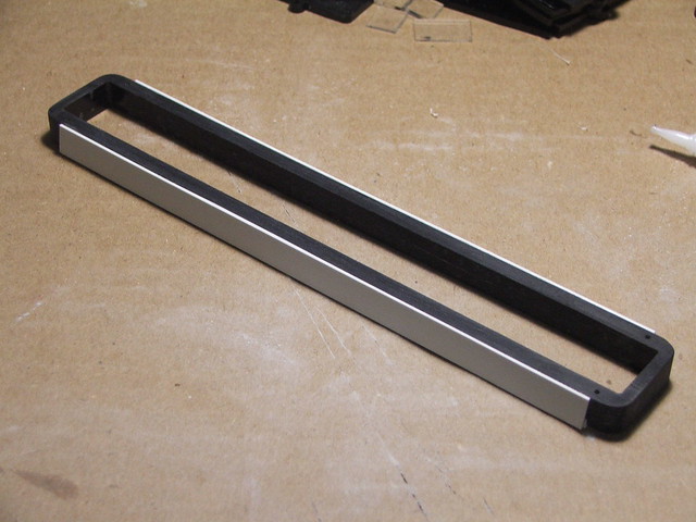
I built this in three sections of acrylic to get the proper thickness. There was a lot of sanding to get all the edges flush (fun fact, laser cuts aren’t exactly 90º!) but here is the end result, with some styrene accents.
Aaaaand more moldmaking! Lego mold box, because that’s the way professionals do it (?)
I also set about assembling the various flat-packed IKEA-style Gravity Gun into something a bit more recognizable. All of these parts had to be sanded before assembly, since the laser makes a slight lip around the edge from heating the plastic which would keep them from layering correctly. Also, lasers do cut glass-clear on their edges, but not glass-smooth; all of the facing edges also had to be sanded to remove the tool marks.
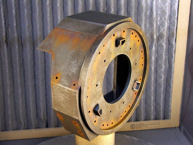
The main barrel assembly. For this part alone I was happy to have gone with laser cutting. 8 total layers make up this part, and each of the claw arm bases around the perimeter are another 8 parts a piece. 32 parts worth of acrylic, some only 1/8″ wide… I’m really glad I didn’t have to cut all of these by hand!
More parts. This is the assembly of the rear body.
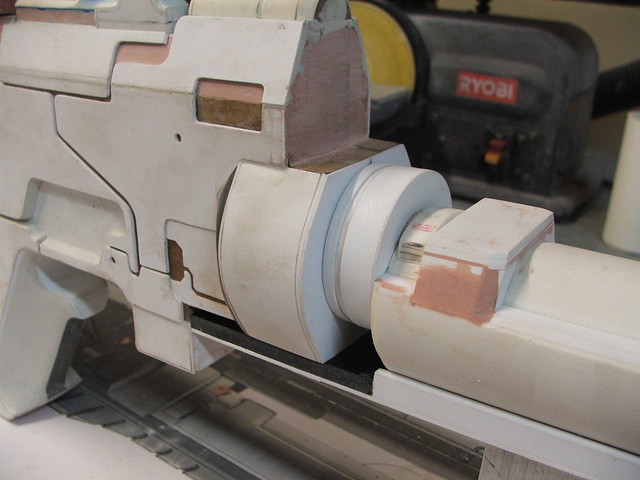
The rear larger drums intersect with the main body in a fairly odd manner. After struggling with a good way to get these parts to fit together, I eventually settled on making a jig out of sintra and cutting the funky angles on my bandsaw. Went together better than expected!
Not everything was planned in advance though, a few parts still had to be scratchbuilt from raw material because I had NO idea how to make them until the rest of the gun was assembled and in front of me.
The lower heat fins, for example. This was a really fun part to piece together by hand! The black parts are all leftover acrylic, while the white fins are .060″ styrene.
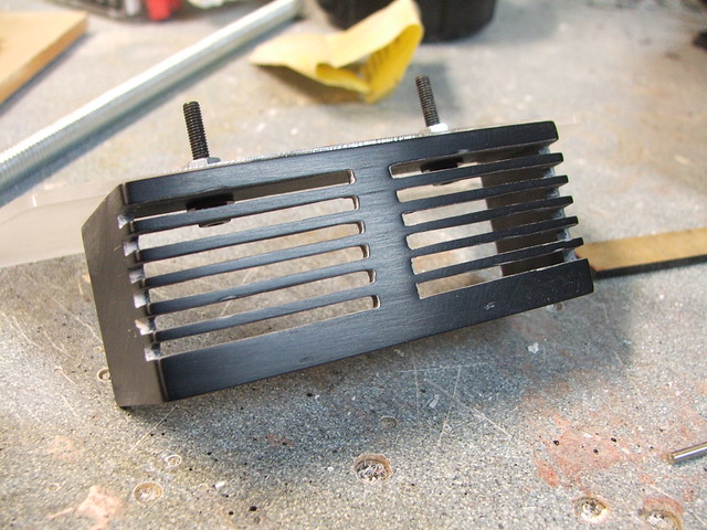
The pic above also shows the completed handle, which was cut and shaped from a block of sintra and some styrene/acrylic/wood mishmash for accents.
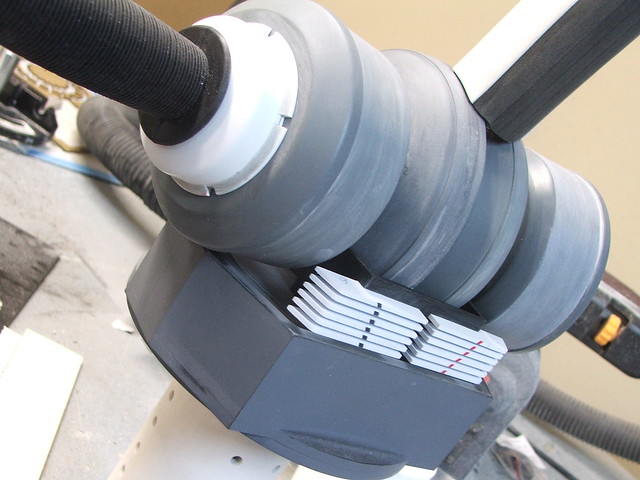
The handle fits over a 5/8″ threaded bar bolted to the rear drum assembly. This in turn is bolted with a similar bar to a piece of PVC that the Xen crystals, barrel, and long rectangular brackets mount to. Its a delicate balance, held in place with about 60 screws and bolts!

I had originally intended to make the Xen crystals out of laser-cut MDF, but the “not-quite-90º-cuts” made this plan a loss. I remade the Xen crystal master out of a sintra block, and cut the “M” shaped bevel with my table router. That was a bit of a nervous experience, but it worked!
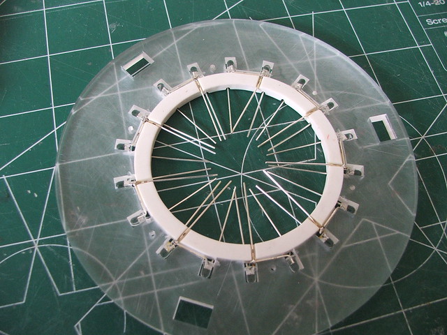
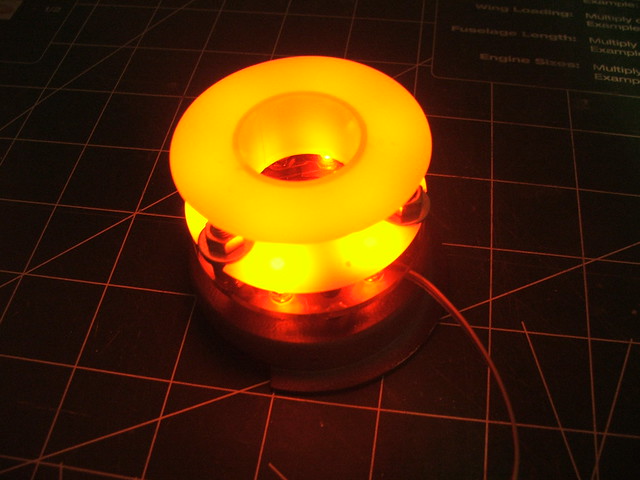
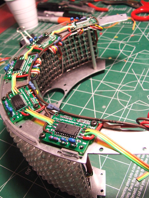
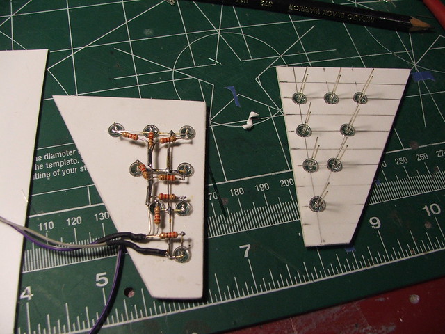
More moldmaking! To get the pieces to show light, I drilled out small pucks to act as lenses in the material and scatter the illumination from a series of LEDs that would be mounted underneath. The parts themselves were cast in Smooth Cast 325 plastic, which dries translucent white.
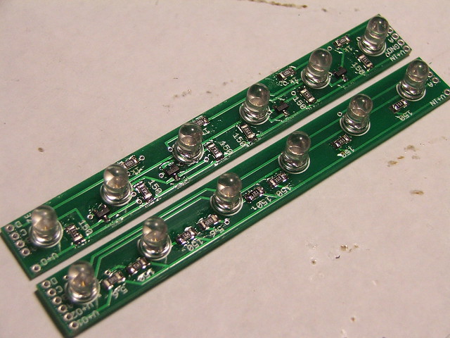
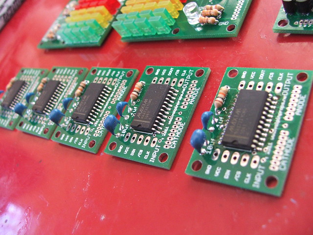
The LED boards, designed in Eagle and printed at Batch PCB. The free version of Eagle only lets you design in a 5″x5″ work area, so the 7.5″ long boards needed to be sectioned in two halves and jumpered together after assembly. Fun!
More illumination was needed for the “vent” piece on the main body. This panel has 2 rare earth magnets inside it, securing it onto the battery tray on the side of the gun. Illuminated battery doors, why not?
With almost all the parts finally cast and assembled, it was time for a test fitting!
There was light at the end of the tunnel, but still some parts left to be built.
The barrel needed some modifications – I had neglected to make the mounts for the brackets when I had the acrylic cut, so these were added with more scrap acrylic and screwed to the barrel surround.


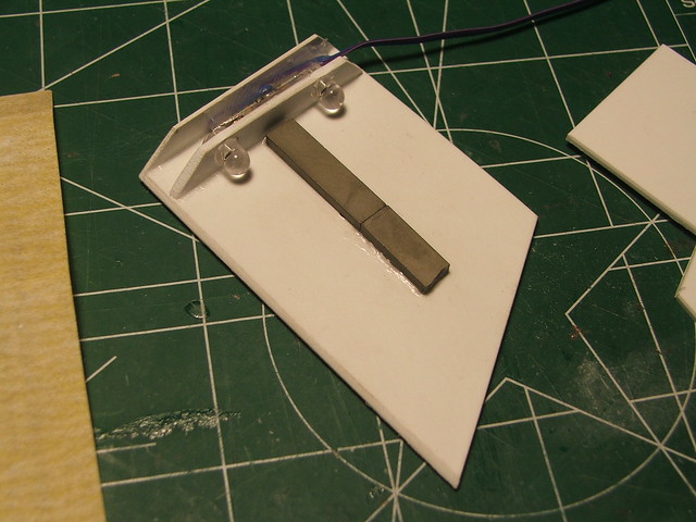
There was also the matter of that little gauge near the handle. Emphasis here on little – this thing isn’t even 3/4″ in diameter! Its secured to the gun with duct tape in the game, but using actual duct tape would be a poor idea. It will shrink over time and leave behind a gross residue. I needed something more archival. By mounting the gauge to the handle drum with painter’s tape, I blocked out a rough shape of the tape form.
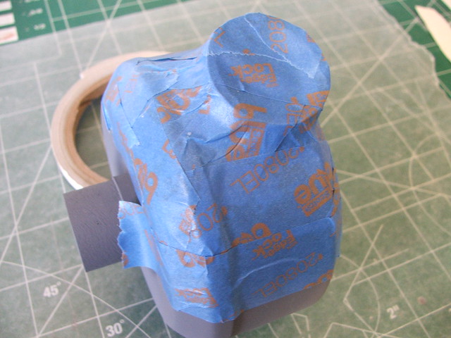
I used this as a sort of mold to lay strips of resin-soaked cloth on top of. Once the resin was fully cured, I popped it off the tape and cleaned up the edges. Just needs a little paint and we’ve got faux duct tape!


A fellow forum member on the RPF extracted the texture of the gauge face for me, which I remade in Photoshop and had printed onto adhesive-backed vinyl. Some people think the “U2” in the upper right should have read “200” but its debatable…
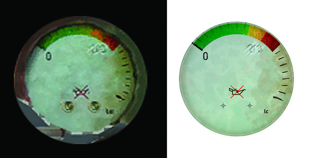
Teeny tiny screws were pirated out of a dead walkman (never toss out old electronics!) and the needle is made from a shaved down roofing staple mounted to an earring back pin. Hacked-together? Yes, but it looks the part!

Those were the last parts that needed to be built, so it was onto paint!
…after I scribed some deeper panel lines first.
Okay, now paint! Everything got a layer of gray primer first…

Followed by a whole bunch of silver. The metals on the various parts of the gun are a whole bunch of different colors, so some parts got darker basecoats than others. There were somewhere around 60 separate parts that all had to be painted individually before weathering, then assembly. This stage took the better part of a week.


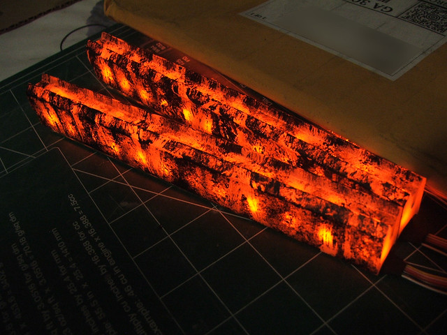
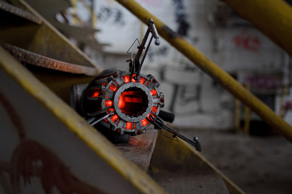
While I was waiting on those bits to dry (I need to occupy myself during that time, I’m the sort of person who will get fingerprints all over wet paint due to my complete lack of patience) I turned my attention to working on the weathering for the Xen crystals.
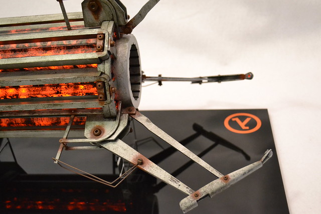
Each part was painted first by dabbing black acrylic paint over the entire surface with a piece of rolled-up newsprint. After this dried, I went back and scratched off sections in vertical strokes along the length of the part to give the surface a bit more variation. When lit, I was hoping for the effect of red-hot metal, or perhaps lava. The results were great.
The clear section of the barrel also has LEDs – these illuminate the small windows in the barrel front and pulse in time with the Xen crystals. Parts like this are also what makes laser cutting such a great solution for propmaking.
Lastly, I wanted something to look at if you were to stare down the barrel of the gun. This little assembly is more hackery with found parts – 6 LEDs illuminate a plastic solder spool salvaged from my “spare plastic” bin. The effect at the base of the barrel section is pretty cool to look at.
Only two more steps (ha!) before final assembly: weathering and wiring. Its really easy to rush here, but I think weathering will make or break a prop. I had to summon as much of my non-existent patience as possible.
I think of the Gravity Gun as a utilitarian piece of technology. It seems like something that may have been at home in a lab, but has been re-purposed by the resistance in the world of Half-Life and forced into more heavy duty than it was originally intended for. I don’t think the scientists behind the design would have spent time with rust preventative paint a fancy finish. This is a piece of tech meant for work, not aesthetics.
The rust here starts off with a basecoat of purple acrylic airbrushed around seams and screw holes. These areas would see the most “wear” and stripping of paint, so they would be the first to start rusting. After the purple dries, a dark red is stipled on with a small coarse brush. This is followed with a lighter orange, and eventually yellow on top of that.
Certain areas (like the seam line in the image above) also had a small amount of water dripped onto the wet paint to give the surface rust a little bit of a run.

All of the parts were weathered and clearcoated individually before assembly.

Assembled, the rusted joints start to (hopefully!) make some sense.

Sub-assemblies started to come together, and for the first time I felt confident about making my deadline! (note the red button there – another salvaged walkman part!)

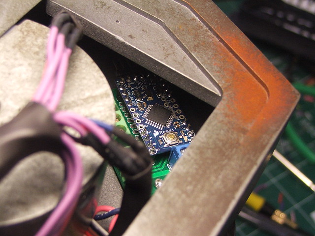
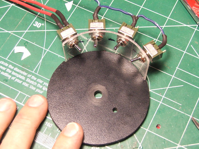
The electronics in the gun are controlled by an Arduino mini. Each of the light bars has 12 LEDs that pulse in 4 random patterns along the barrel. The arduino is turned on and off with a small switch on the underside of the main gun body.
First test fire! I used some screen mesh material to give the barrel interior a little more texture between the LED circuitboards.

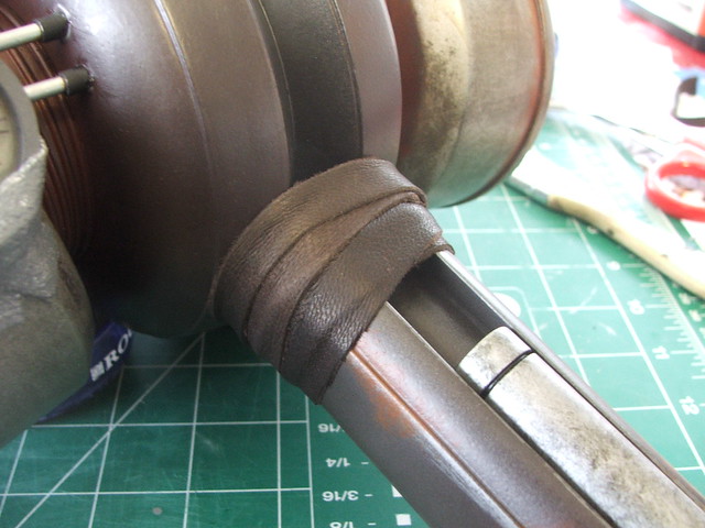
Details, details. At the last minute I remembered I had forgotten the handle wrap and the valve pressure lines!
This is a HUGE post, and to anyone who has read this far I salute your perseverance. Believe it or not, there’s actually lot of this build I’ve left out of this entry. If you want the entire play-by-play, then check out my Flickr stream here for more images and notes on the project. I could easily fill 2 more entries of similar length to this one with the nitty-gritty, but I have a feeling that may be overlkill…
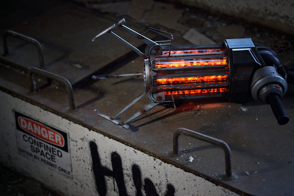
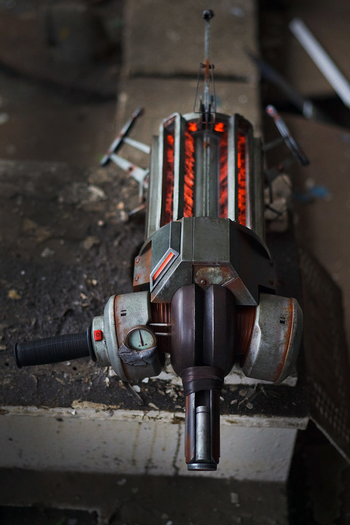
The finished product!

If you haven’t seen Dan’s awesome photography already, be sure to check out that entry here. Below are a few more close-up shots of the finished gun that show off more of the details.


Thanks for reading, and happy 2012!

Gravity Gun for Child’s Play
Last year, I got it in my head to put together a Portal Gun for the Penny Arcade Child’s Play annual charity dinner in Seattle. Child’s Play is an awesome cause, and one I am very happy to support. Gamers often get a pretty bad reputation in media and the public eye, but this organization has been pulling together millions of dollars for children’s hospitals for years now and has really shown what our community is capable of.
Well, last year went fantastically, and the auction is coming up again tomorrow. I really went down to the wire on this one, but this year I’ll be bringing a Gravity Gun from Valve’s Half Life franchise for auction.

The Gravity Gun has been a little bit of a combination of white-whale-unattainable and Sistine-Chapel-level-intimidating for me ever since I thought about getting into propmaking. Its complicated, intricate, and if I didn’t get it just right, I’d have about a million gamers ready to tell me exactly why.

Normally I don’t toss up show-off posts with just pictures, but as the auction is tomorrow, I really wanted to get the word out about this piece. If you’d like to contribute, certain lots will be available for proxy bidding over the phone. This means you don’t necessarily have to be at the dinner in order to bid! If you’re interested, please contact Jamie Dillion at jdillion@childsplaycharity.org to learn about remote participation.
I should note that the Portal Gun fetched a little more than twice what my car is worth, so if you’re planning on proxy bidding then be prepared!
I will have a process blog post about the build of the Gravity Gun, as per my usual style, in the coming weeks. Until then, please enjoy these fantastic photos by my friend Dan Almasy. (Facebook in the link, Flickr here)


Finally, thank you to everyone in the gaming community for making things like this happen.


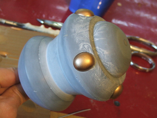
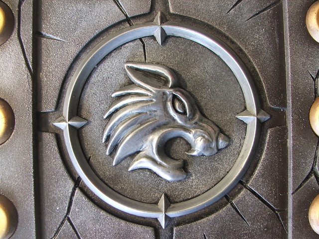
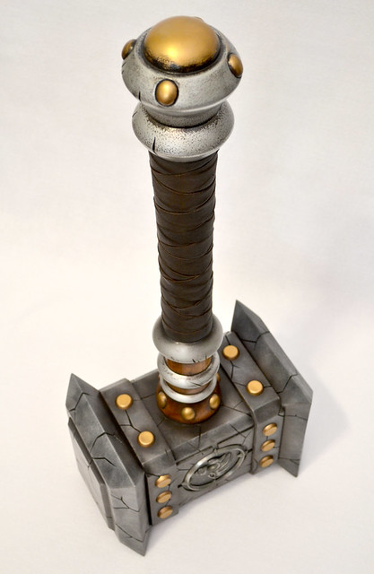
Thrall’s Doomhammer, Warcraft
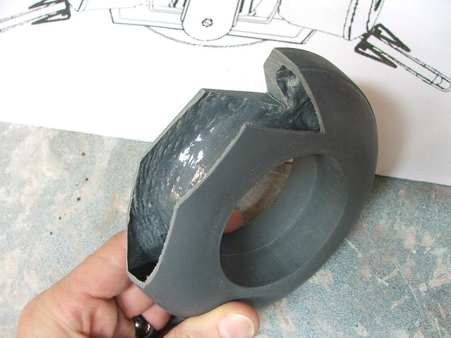
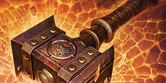
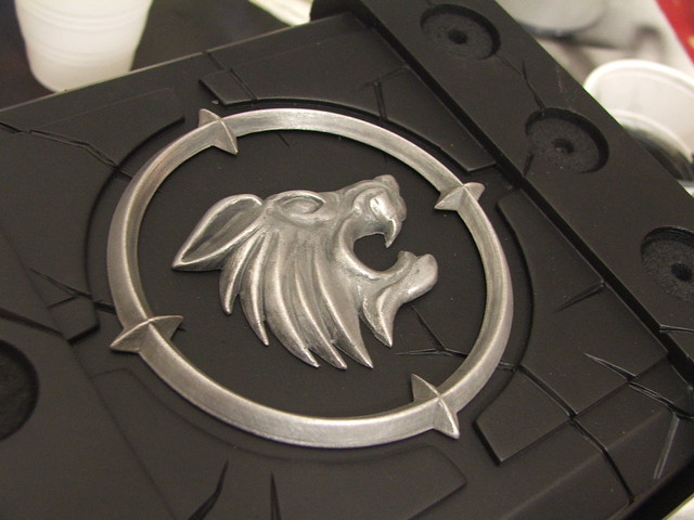
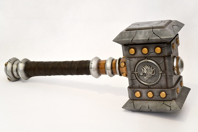
A friend of mine who takes costume commissions (Check out her work at God Save The Queen Fashions!) sent me an inquiry a few months ago asking if I had any interest in helping her put together a few accessories for a World of Warcraft project she had coming up. The character was the Warchief Thrall, and he needed his iconic Doomhammer.There are a lot of versions of this weapon floating around, but it was decided that the source would be the Doomhammer as it was shown on the cover of the novel “The Shattering”
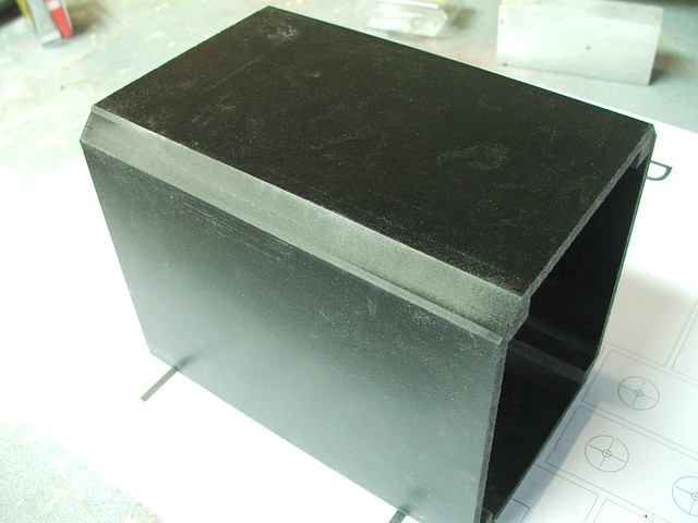
From this reference and a couple others, I put together some blueprints in Illustrator. The finished result would be formidable and quite large, but just a bit shy of gigantic. 30″ tip to tail, to be specific. To keep things as lightweight as possible, I decided to construct the head of the hammer in hollow sections. I used 3/8″ sintra sheets to make the main box of the head, then angled the sides with a 45º router bit.
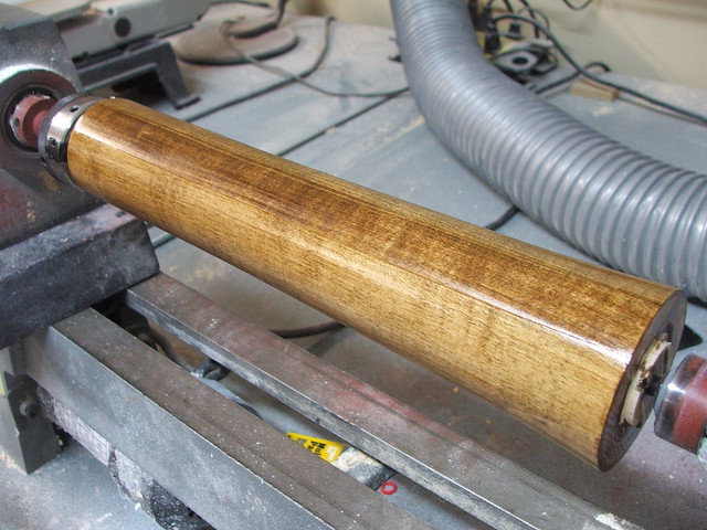
Other lathed bits included the handle, head stock, and pommel. The first two were cut from laminated maple boards, while the last one was cut from another block of casting resin. After the maple was turned, the parts were stained dark brown and sealed with urethane varnish.Its worth mentioning that these started out as 4″x1″ planks. After laminating, cutting these shapes from 4″ blocks was a nightmare on my crappy Harbor Freight lathe. This project really did a number on the lathe head, so I think now is a good time to upgrade.
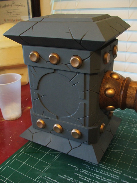
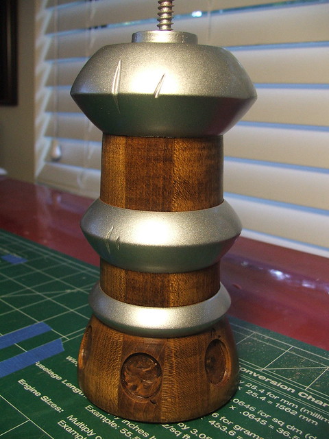
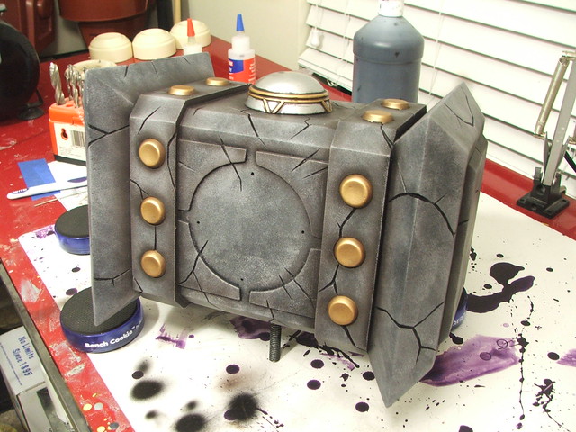

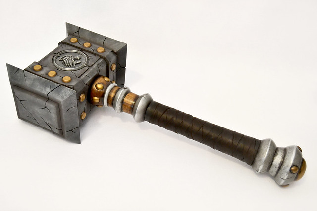
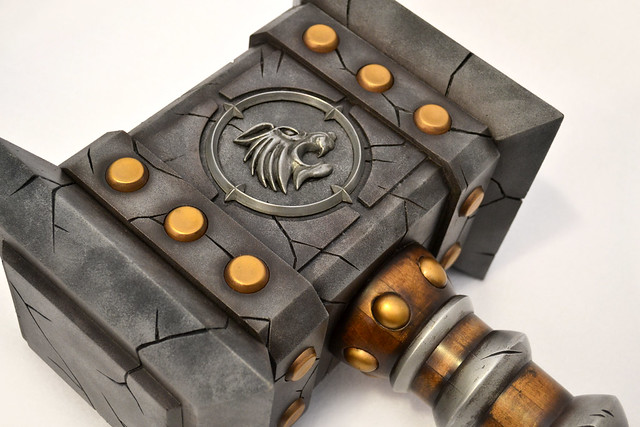
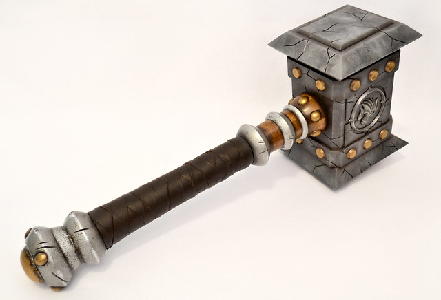
The final piece after assembly and clearcoat! Final dimensions of the piece are 30.5″ long, with the head measuring 7″x9″x11.5″ – total weight is a pretty manageable 8.5lbs! Not bad for such a giant prop.
If you’re looking for more process photos (or the final shots in higher resolution!) check out my flickr page – there’s a lot more there which aren’t included in this write-up.

Daft DeLorean photoshoot!
If you’re just arriving on this page, please be sure to visit parts one two and three of this build, which showcase the sculpting moldmaking and electronics aspects of the project.
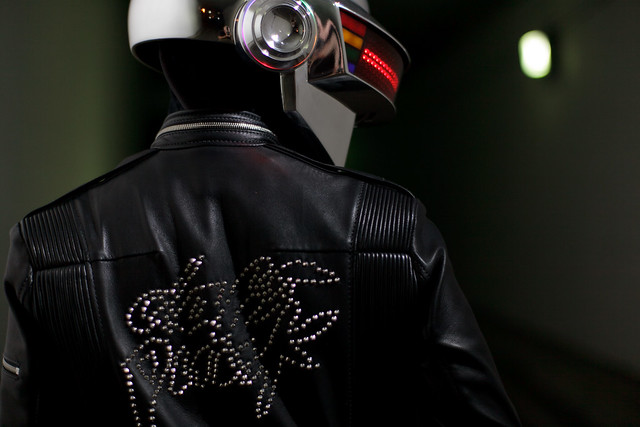
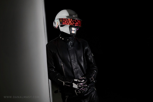
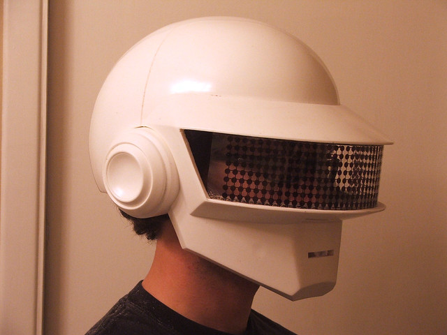
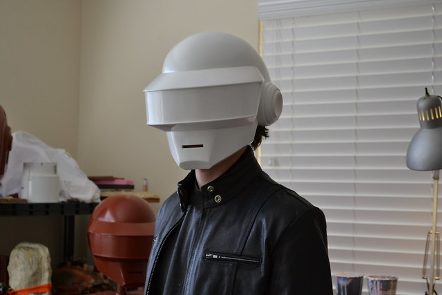
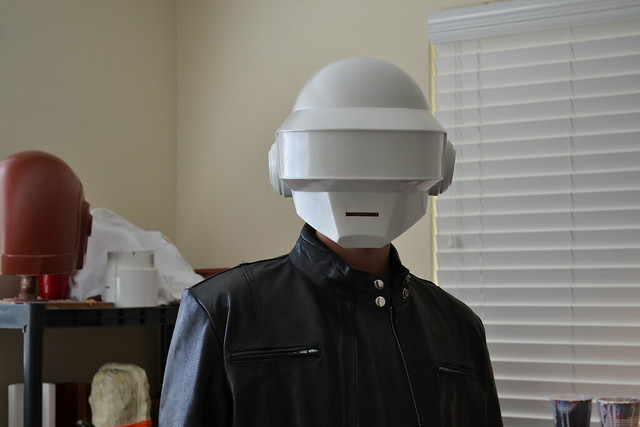
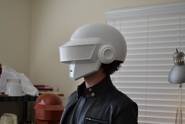
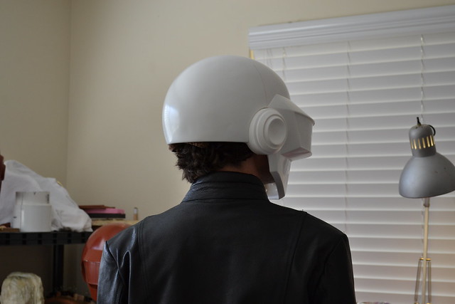
I haven’t done a photoshoot post since 2009 with the Big Daddy suit at the Aquarium, but the Thomas helmet brought in some of the most beautiful shots I’ve ever had taken of my work. Pair this with the fact that Catherine of God Save The Queen Fashions created an absolutely perfect replica of Daft Punk’s “Human After All” era leather costumes, and the overall illusion is simply spectacular.
As with my other entry, I would be remiss to neglect mentioning all the help I had with this project. It would not have come together without the efforts of the following people:
Coding for this helmet (Arduino and iOS) was handled by James Moss
The Daft Punk leather suit, which you see below, was fabricated by Catherine Jones of God Save The Queen Fashions
Chroming of the helmet and gloves was handled by Creations n’ Chrome
Photography on this page is courtesy of Dan Almasy
Custom circuit board printing was handled by Batch PCB.com
Awesome DeLorean provided for the photoshoot by Derek Lukaschus
First, the recap video because if you don’t want to read the process, at least you can watch it!
Now, onto the pictures!


Thanks for taking a look!

Want more pictures? Higher resolution? Check out my Flickr stream!

Daft Punk Helmet (Thomas) Final!
Its been a long road, but not nearly as long as my Guy Manuel project. I learned a lot from Guy, most notably what NOT to do, which allowed me to streamline this process considerably. The end result was more solid, more polished, more professional, and about ten times a complex as the Guy helmet, and it gives me a special pleasure to announce it finished.
Before I get into the “how-I-did-it” thing, some credit is due to fantastic artisans who assisted in helping me bring this project to light. Below you’ll find each specialist’s web page, and I can say their work is of the absolute highest caliber.
Coding for this helmet (Arduino and iOS) was handled by James Moss
The Daft Punk leather suit, which you see below, was fabricated by Catherine Jones of God Save The Queen Fashions
Chroming of the helmet and gloves was handled by Creations n’ Chrome
2 photographs below and the last on this page, courtesy of Dan Almasy
Custom circuit board printing was handled by Batch PCB.com
Awesome DeLorean provided for the photoshoot by Derek Lukaschus
If you’re just arriving on this page, please be sure to visit parts one and two of this build, which showcase the sculpting and moldmaking aspects of the project.
Don’t feel like reading? You’re in luck! 4 months go by in 3 and a half minutes:
And, if you’d rather just see more pretty pictures like the ones below and skip all the sawdust and soldering, feel free to hit this link to see more fancy photowork.

Onto the build! The last time I had an update on the project, the mold had been finalized and I had one prepped polyester resin casting heading out for chrome work.
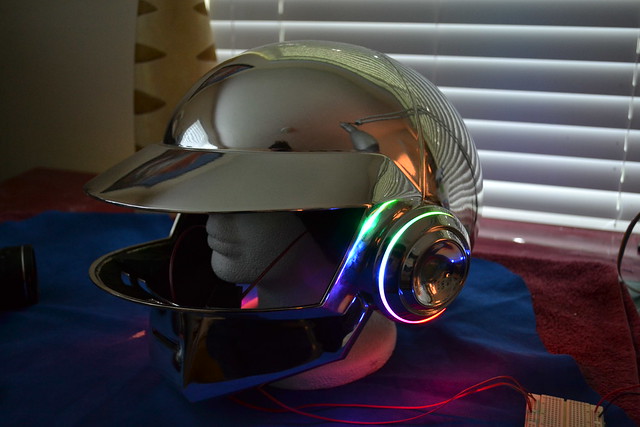
While this was out at Creations n Chrome, I got to work on the visor LED matrix. To check for some semblance of visibility, I made a mockup printed on transparency film of where the LEDs and wire traces would be situated. Nothing exact, but good enough for a proof-of-theory.
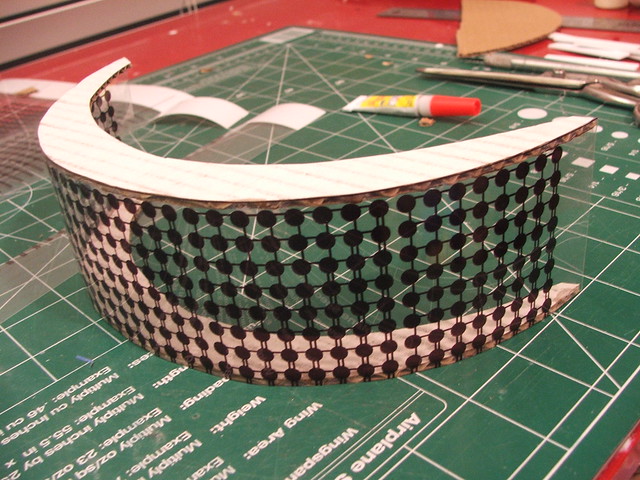
Vision was adequate, which was very encouraging!
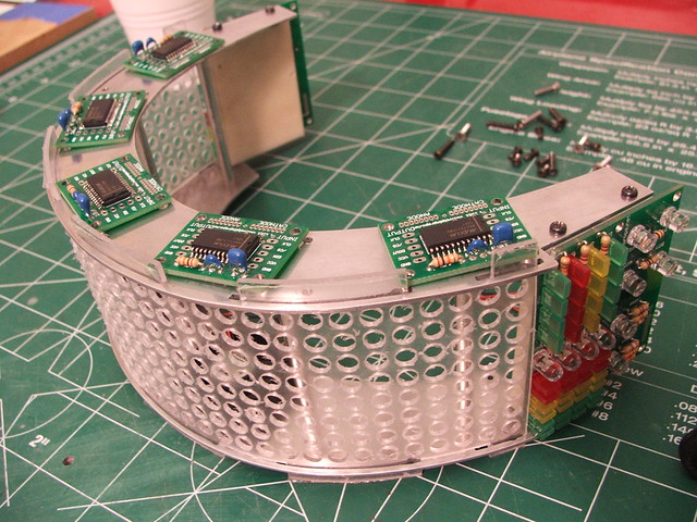
I decided the actual structure to hold the matrix in place would be built from 2 sections of 1/16″ aluminum plate, with the drilled-out subvisor tension-fit between them. Below was the start of all that ambition.

After scribing all the lines, the plates were cut on a scrollsaw. The two large holes in the plate are where two vent fans are situated, which pull fresh air in through the lower nose vents on the underside of the visor. I can’t say enough how much these saved my live when wearing the helmet, especially in the Atlanta heat in summer.
Uprights were cut from 3/16″ aluminum hollow tube, and tapped to accept a machine screw. 5 of these hold the plated parallel to one another.
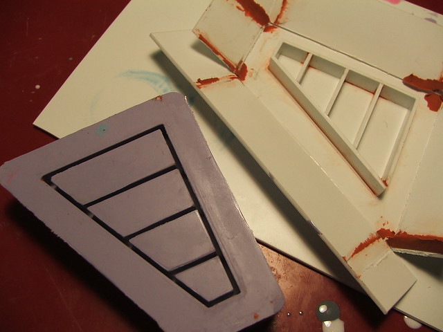
This styrene plate was the mockup for the subvisor. You can see the tabs on the top which align with cutouts on the mounting plates. This has a double feature of keeping the subvisor bent on a gradual curve as well as keeping the entire thing in place without the need for any glue joints.

Quick test with my mockup helmet to make sure everything fits!
Then came the drilling… All the holes for the subvisor were drilled by hand on my drill press. The material used was .060″ PET plastic.

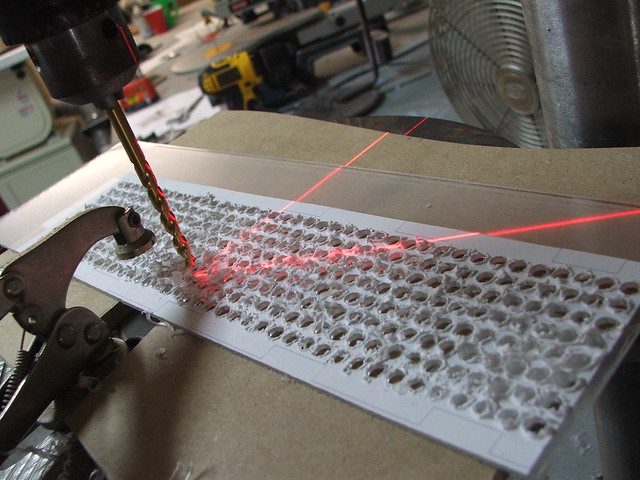
More mounting points were drilled and tapped into the subvisor frame to allow for the circuit boards to be mounted later. If you go this route, make sure to insulate your boards against the aluminum to prevent dead shorts and the dreaded blue smoke.
And then I polished them. Because, why not?
The subvisor with protective plastic still in place. 320 holes!
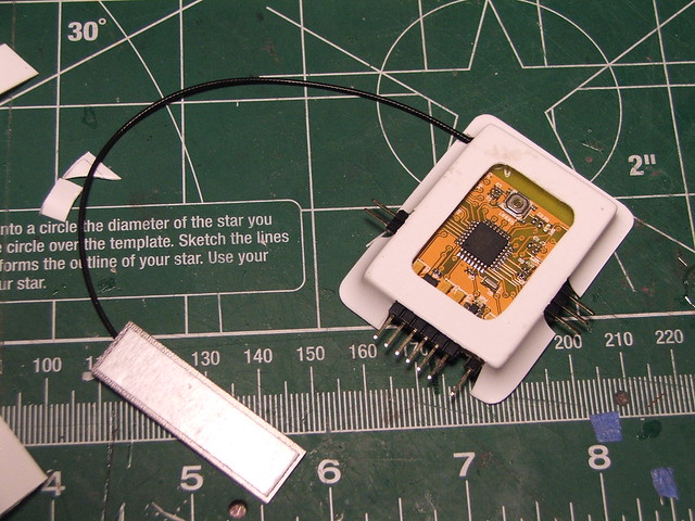
These are the chips that drive the matrix. Each holds one MAX7221 multiplexing LED driver with input as well as output sides of the board to make this a scalable design. Each will drive one 8×8 matrix and are designed to be daisy-chained together. Boards were designed in CadSoft’s Eagle PCB editor. They’re not a bad design, but there are improvements to be made in future designs.
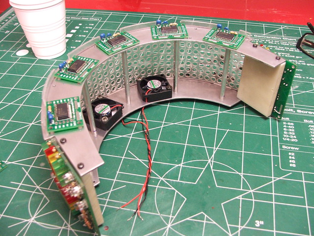
You can see the 2 small 5V fans situated on the subvisor frame below.
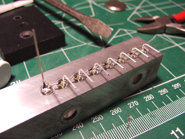
Since I needed to bend the leads on 320 red LEDs, I made a small jig to keep things a little more precise. Using this, I only had one in all 320 wired backwards when it came time for testing! If you’re looking for LEDs for your next project, I get mine from SuperBrightLEDs.com
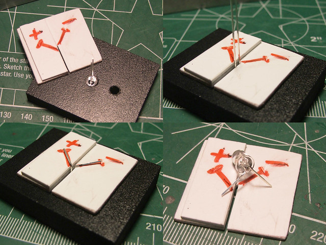
A second jig was made in some scarp aluminum square tube for soldering the columns together. Since the subvisor curve is a simple (that is, one axis) curve, I was able to do these solder joints outside the assembly.
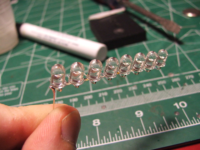
Repeat 40 times.
Once the columns were in place, I was able to solder the rows together.

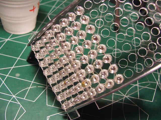
Since nothing was glued in at this point, I was able to push the LEDs back out of the subvisor and wire up the rows and columns without worrying about getting crud all over the clear PET sheet. At this point, I also painted the backs of all the LEDs black to reduce the amount of light leaking back into the helmet, and the wearer’s eyes.

And then mounted back into the subvisor frame. A lot of tidying up to do.
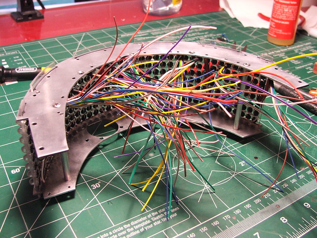
This was an exercise in frustration. Next time, I’ll be sacrificing board size in order to have slightly larger solder pads for the matrices. Bleh.
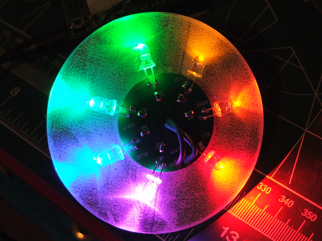
A comment from a fellow member of the Replica Prop Forum asked if I was going to be adding Thomas’ ear LEDs as well. I hadn’t planned on it, but the more I considered the idea the more I wanted something there. These are simple I/O boards which illuminate a clear disc mounted in the ears with 7 different colors. The final effect was well worth it!

I also tossed together a quick mold of for the side light bars. Easier than building 2 from scratch and trying to make them identical!
In the end, my fancy boards for the side lights got pushed out of the way by my slightly ambitious 8×40 matrix. I made some simple I/O lights (literally days before the debut of the helmet at Dragon*Con in Atlanta!) to fill the gap left behind. The lead arrangement on them isn’t my most stunning work, but they get the job done.
To bolster my spirits somewhat after this small letdown, I got the following photo form Creations n’ Chrome. Stunning.
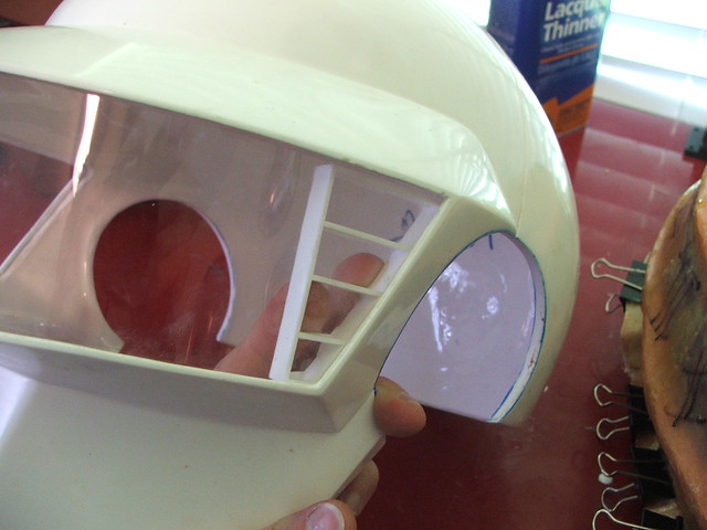
Still more to do! I put together a visor buck from MDF and styrene sheet for the PET visors. My first attempt at vacuumforming went alright, but the draw distance was rather far and the final piece was a bit too thin.
Instead, I strapped a 2.5″ tall sheet of PET plastic to the buck, then heated it with a heat gun until it held shape. Perfect!
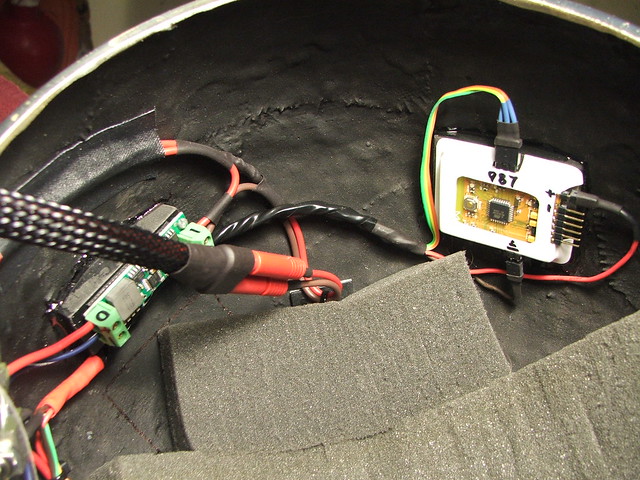
At this point, things needed to start going into that shiny chrome bucket. First went the ear lights, shown here being tested off a breadboard until the power supply was finalized.
Then the visor went into place. I don’t have much in the way of documentation on this process, but if you’re interested in using RIT dye to tint PET plastic, check out this post on the RPF. Tekparasite uses one of my helmets in his project, and came up with a really great method of getting superb results without all the finisky nonsense of niteshades spray tint.
The matrix is controlled by an Arduino Yellowjacket. James cooked up an iOS program that allows the helmet text to be changed over WiFi, as well as allowing the user to select certain patterns. For Dragon*Con, a switch was implemented that ran down my sleeve so I could toggle through animations more easily. The hardest part isn’t seeing or controlling an iPhone with the helmet on, its actually getting it out of your pocket with those glove plates in the way!
This switch plate, mounted to one of the ear pucks, controls various parts of electronics. From left: 5V regulator, YellowJacket & matrix, corner & ear lights, vent fans.
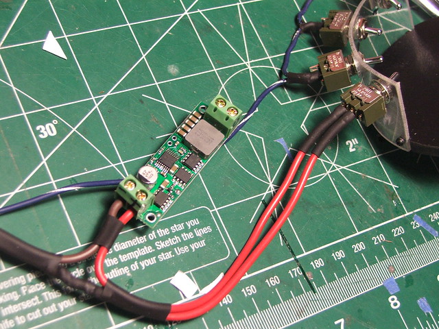
The aforementioned voltage regulator. After building my own linear regulator (and finding out it would probably set my hair on fire) I decided to order this one from Pololu. 7A continuous current and up to 24V input! My helmet ran on 11.1V 3S LiPo batteries, but could have easily run on a 7.2V 2S as well.
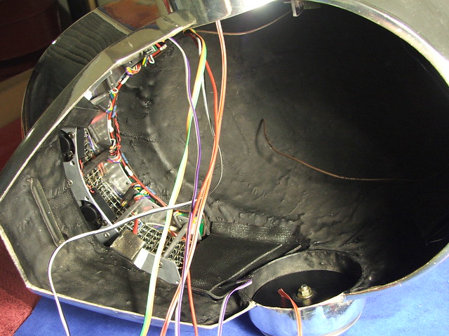
Vent fan placement – remember, if you live anywhere that gets above 50ºF outside, you need these!
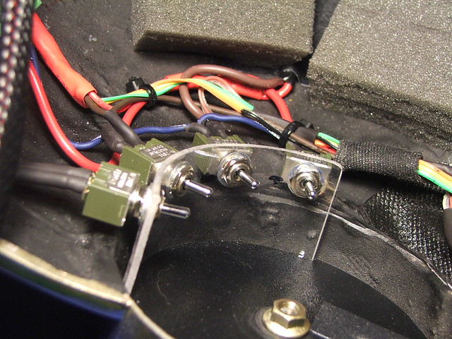
A few images of the final wiring getting tidied up.
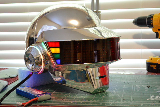
It works! With the LEDs off and with ambient lighting, you can see the matrix behind the visor. Since I decided against using video glasses or a camera, I needed the visor to be as light as possible to avoid light reflection back into the helmet. For those who will ask – you can see very well with the helmet on! The brighter it is outside, the easier it is to see as the incoming light is stronger than the ambient light inside the helmet.
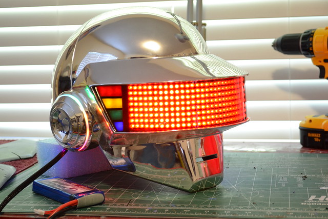
That said, if you try to wear it in pitch black, you’re pretty much blind. Still, it looks cool!
Below are just a few of some of the amazing pictures my friends have taken of this bucket for me. There are more on my Daft Punk Thomas Photography blog entry, so be sure to check that out as well!
Images courtesy of Bill Doran: (see his Flickr for more images here)


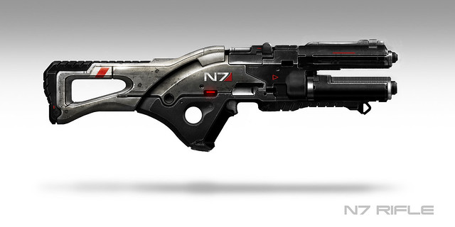
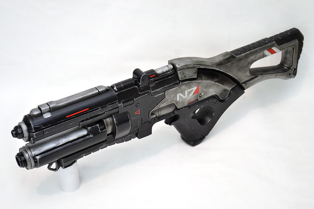
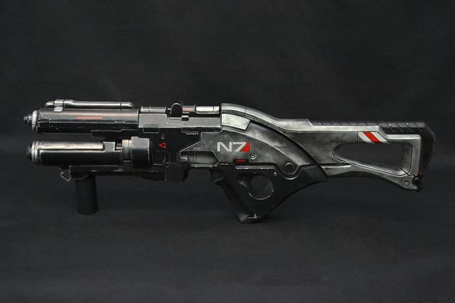
N7 Rifle, Mass Effect 3
Its been roughly a year since I worked on anything from the Mass Effect universe, but E3 2011 was ripe with news from the third installment of the franchise, due out next year. I’m a huge Mass Effect fan, so when the guys at Bioware asked if I’d be interested in making a weapon for them as a part of the press push for ME3… well, I think you can figure out what my answer was.
This is the N7 rifle (which, at the time of this writing, I don’t think has even been formally announced yet!) It’s an Assault Rifle which takes cues from the weapons included in the collector’s edition of Mass Effect 3. Its style mirrors the already-announced N7 pistol, shotgun, sniper rifle and SMG.
The guys at Bioware wanted theirs ready for San Diego Comic-Con 2011, which gave me roughly 14 working days. LETS GO!
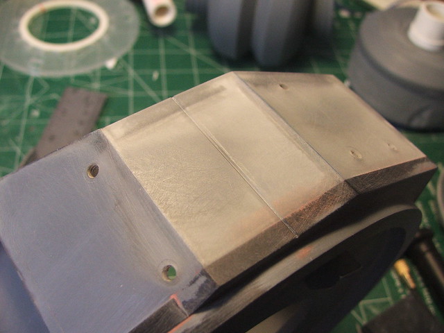
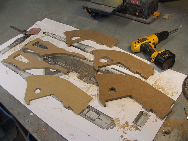
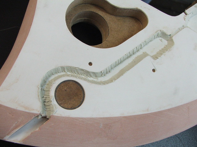
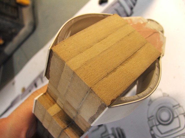
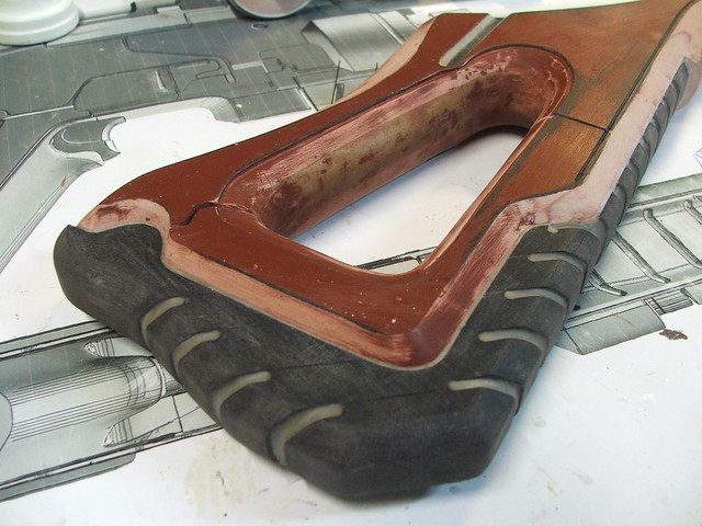
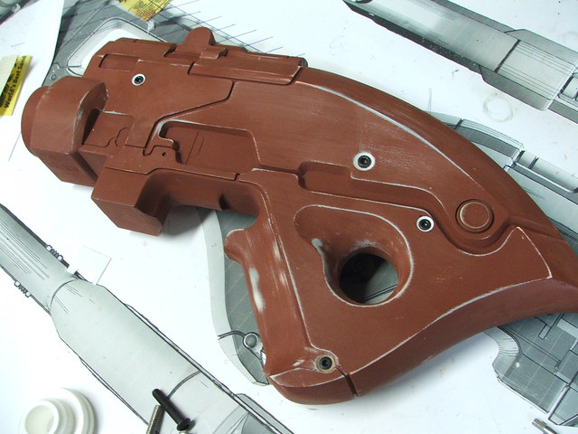
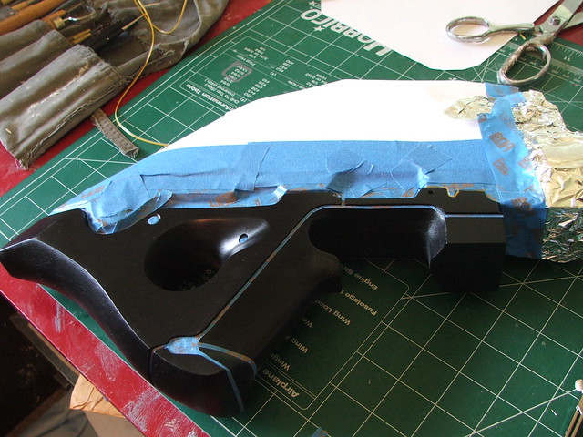
I started in a very familiar way – drafting out line art patterns onto MDF. These shapes here are what I decided to call the “main body” of the rifle.
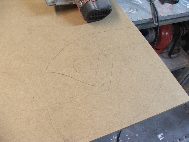
The idea was to make the rifle in several different parts which would be molded and painted separately, then assembled and weathered as the finished rifle. Here you see parts for the main body and rear stock cut out.
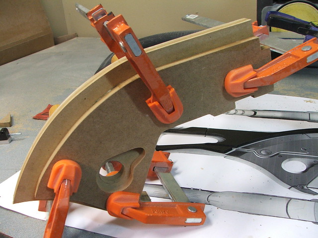
These layered parts were glued and clamped to dry.
On the rear stock, a shape trimmed from 1/4″ sintra marks the area where the rifle edges curve up to a flat facing surface. This will make a bit more sense later.
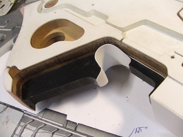
To add dimension to the side of the rifle, a channel was carved out of the top layer of MDF with a dremel tool. Afterward, a piece of styrene is dropped in to make a flat surface – this is much easier than trying to sand something smooth in a tiny area.
In the shot above, you can see the “step” in the MDF body of the rifle has been filled with green foam. This was then skimmed with bondo to make the large bevel seen on the trailing edge of the main body. I’m missing photos of it, but the rear stock was treated in the same way with the sintra layer acting as the upper edge.
The rest of the raised detailing and panel lines for the body of the rifle were made by cutting .080″ styrene sheet. These pieces were first joined with double-sided tape before being trimmed on my scrollsaw, to make sure they were perfectly symmetrical.
Here’s the styrene plates in place on the rifle body.
Gluing styrene to wood is odd, but I’ve found that if you brush a coat of sealer (in this case because of the fast timeline, I used superglue) over the MDF, then getting a strong bond is much easier.
The edges of the channel were still raw MDF, so I filled them with apoxie sculpt to make a clean beveled edge. The first shot shows getting the clay in place, and the second is after some smoothing out with clay tools.
The upper details on the main receiver were a mishmash of acrylic rod, PVC, styrene and sintra. If you have the space, keep all your little plastic scraps – there’s no telling when they’ll come in handy!
Case in point, the “drum magazine” shape at the back of the lower barrel was created by bending .040″ styrene sheets over sections of acrylic tube I had left over from my Portal Gun builds.
The rear of the magazine was made from 1/2″ sintra shaped with a dremel.

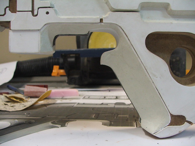
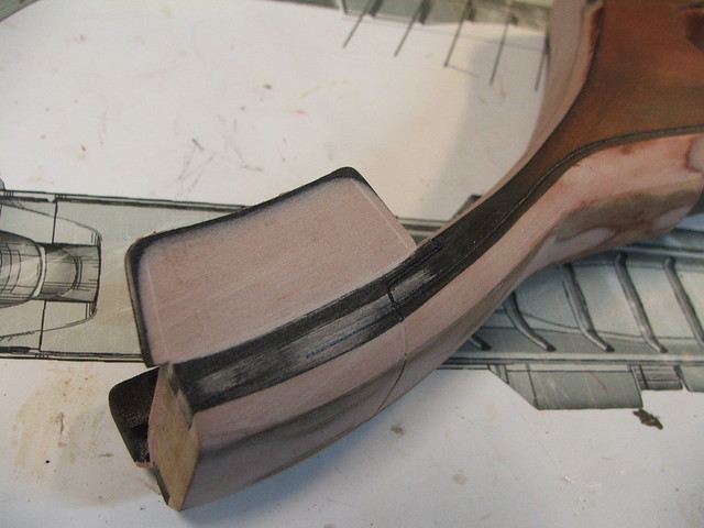
The grip shape started out as a rough spine cut from 1/2″ sintra. The trigger area here has been created with a piece of .020″ styrene. This makes it easier for me to sculpt later.
The actual grip was shaped with Apoxie Sculpt. By mocking in the trigger area earlier, I just had to push the clay into position around it. Much easier than trying to get a clean even curved shape like that by sculpting!
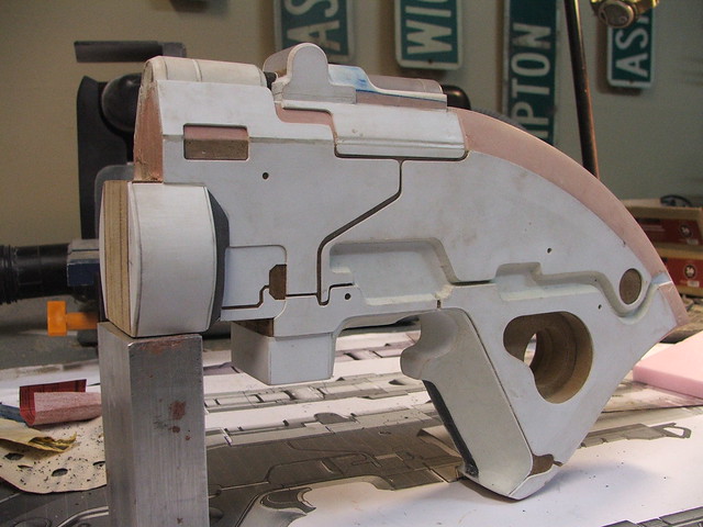
After this addition, the main rifle body is starting to look fairly complete. Certain seams have been filled in with apoxie sculpt in preparation for molding. You have to make sure that there are no open seams which can trap silicone and cause tears in your molds later on. Its tedious, but saves a lot of time in the long run.
With the main body fleshed out, I started work on the barrels. The lower barrel came first, as it was a fairly simple piece to construct. There are 2 PVC pipes nested into one another to create the stepped look, and section of styrene create the beveled edges.
Towards the back of the barrel, additional details were created by making some styrene boxes. Bondo was used to smooth the details into one another. On the backside, I added a PVC connector to sink into a recessed section on the rifle body. This post will make the eventual glued joint on this piece much stronger.
The PVC connector slots into this cylinder, mounted at the front of the rifle body. You can see the connection in the second pic below.
Next up was the lower grip. Since this has to fit to some very complex contours, I decided to make a “base” first which would slot up into the lower barrel and rifle body. By making this piece span across both sections, it provides strength to the final assembled rifle. It is also a section which will be handled fairly often, so it had to be strong. This is the first part, with the front curved section mating to the lower barrel bottom and the back connecting to the rifle body.
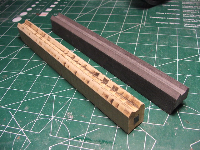
The actual textured part of the grip was first cut from a block of sintra, then several cuts were made to mark the position of the oval-shaped grip lines.
Cutting these in first made sure the lines were in the correct position after the piece was trimmed to shape. The grip was cut down on the sides and front on my bandsaw, followed by some shaping with a dremel.
The cavities left from the cutting were then filled with apoxie sculpt to form the recessed cuts. I repeated a similar process for the grip texture on the rear stock. The D ring on the front of the grip is made from 1/4″ sintra, and the rest of the recessed details are more layered styrene.
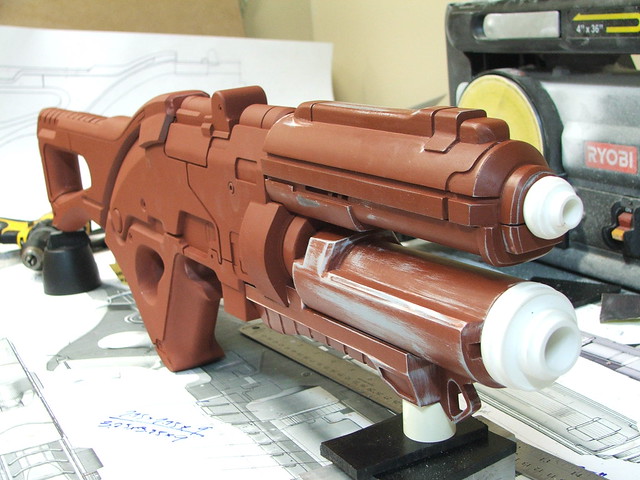
In the first shot above, you can see some work on the upper barrel. With the deadline looming, I unfortunately omitted a lot of the photography of that component as it was being constructed. The upper section is a piece of 3″ PVC pipe with styrene vacuumformed over it to increase its diameter and create panel lines. Both lower sections are 1/2″ sintra shaped on a table router.
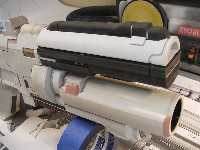
The rather chunky sight rail is made from 3/8″ sintra (it really feels like I’m repeating myself…) as well as the front beveled details. After a few bondo touchups and some sanding, the upper barrel was ready!
There were a few small other details needed before getting the components ready for molding.
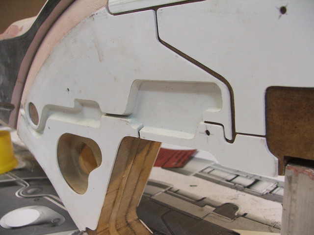
The rear stock needed its finned mounts added…
…the main rifle body needed a couple hex bolts countersunk into the surface (I also scribed a few detail lines in the channel above the trigger and spent a lot of time smoothing the seam lines)…
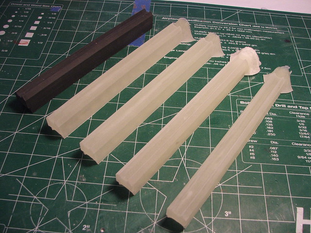
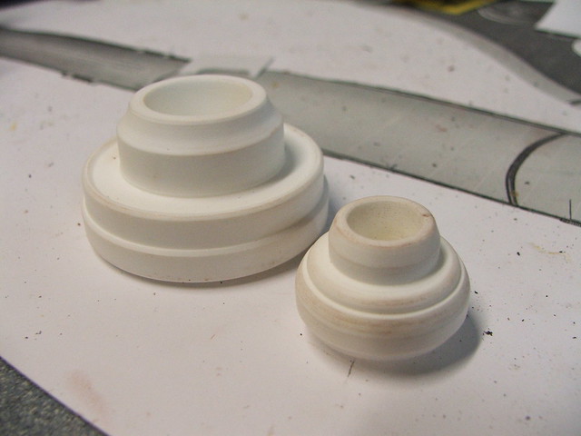
…and the barrel muzzles needed to be lathed out of some resin blocks.
With these details complete, and after a couple dozen hours filling small cracks and divots with spot putty, the gun was ready for silicone!
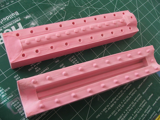
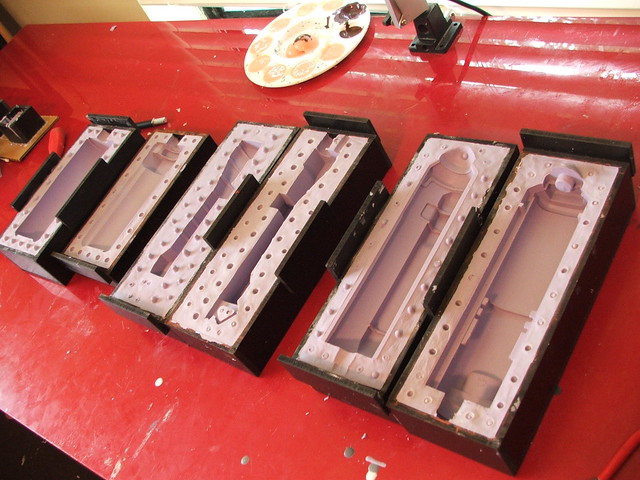
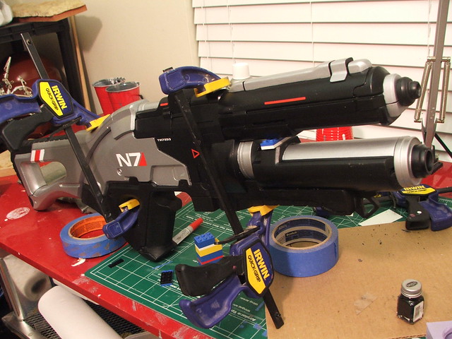
I opted to mold the two barrels and lower grip in simple box molds, while the (much larger) main body and rear stock would be brushed on. The boxes themselves were made out of 1/4″ sintra. MDF would have been cheaper, but sintra glues very quickly and has no pores for silicone to seep into. With time a precious commodity, I went with what was available!
The masters were embedded into one half of the box molds with clay, and sprayed with mold release. After brushing on a thinned coat of silicone (Smooth-on’s “Omoo 30”), the boxes were clamped together and filled with rubber, then allowed to cure overnight.
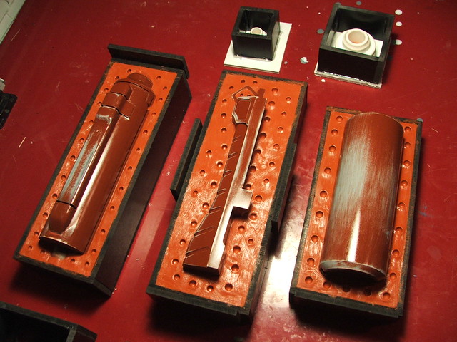
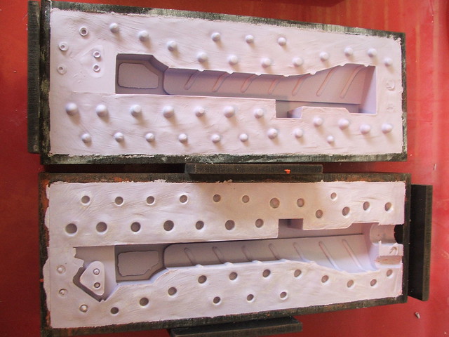
After the first half cured, I repeated the process to the other side. Mold wax was used to keep the silicone from curing to itself. The finished molds were easily some of my best, and yielded fantastic results.
For the body and rear stock, I trimmed sheets of foamcore to fit around the outside of the master. These were then secured in place with a thin clay wall.
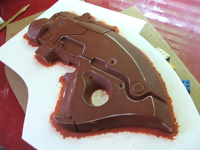
I used Rebound 25 silicone for the brush on molds. If you’ve seen any of my helmet molds, the process is very similar. Thinned brush coat first followed by regular coats, then thickened with registration keys.
The foamcore really made sure I had a clean even edge for both the mold and the mold jacket. After 12 hours of cure time, the pieces were flipped and I molded the opposite side.
The mold jacket is made with Smooth-on’s “Plasti-paste.” A tip about working with it: taking a large stiff brush and going over the surface with rubbing alcohol will smooth out any jagged edges and make the final cured piece much easier to handle.
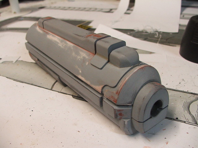
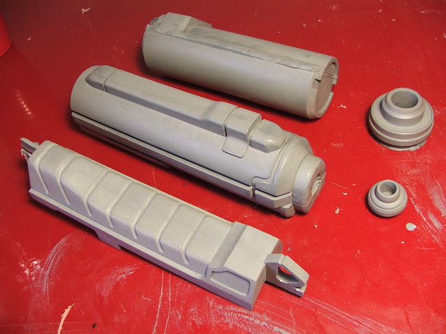
A few shots of the finished molds, in use, and with their first pulled copies. The final pulls needed very little sanding and had almost no trapped air bubbles. I think I’m finally getting the hang of this!

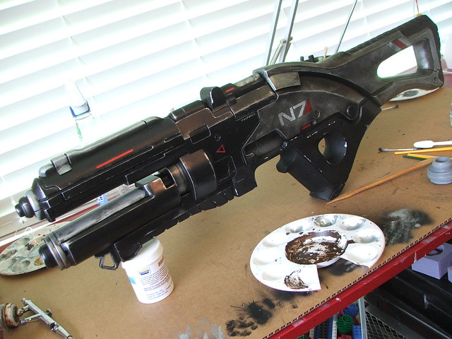
The painting process was, unfortunately, another area where my photo documentation suffered in order to make the deadline. All parts were first painted with satin black, then masked off in various areas for topcoats of silver and texture.
The grip texture was accomplished by first painting the selected area with Rustoleum Multicolored Textured paint, then topcoating in flat black. This creates a much better textured finish that is far more durable than the Plasti-dip spray I used on my prior M8 rifle project.
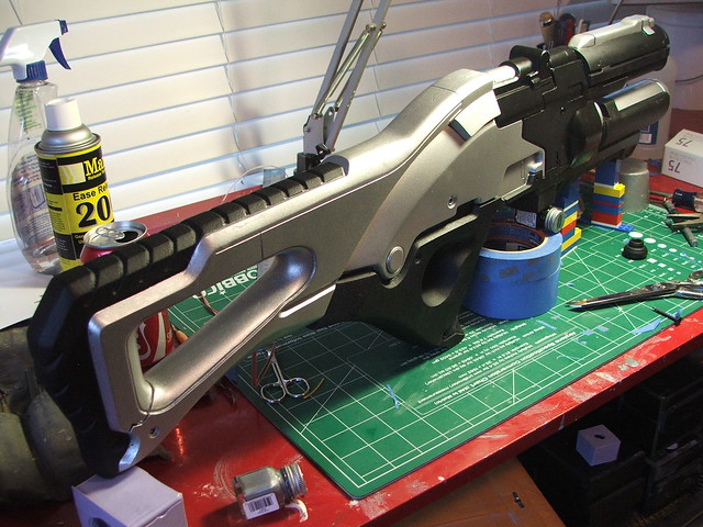
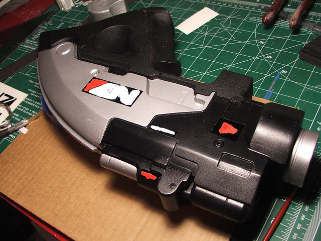
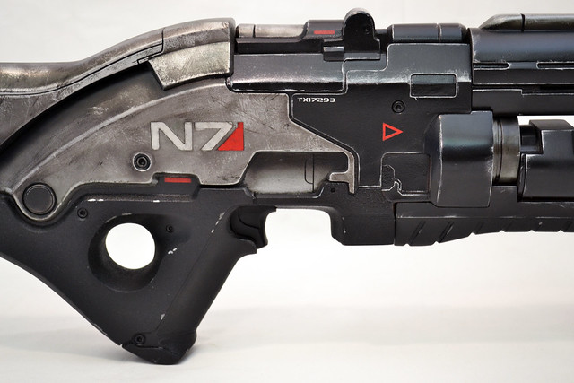
After the base colors were dry, vinyl decals were used to mask off areas for the N7 logo, as well as other text details and line markings.
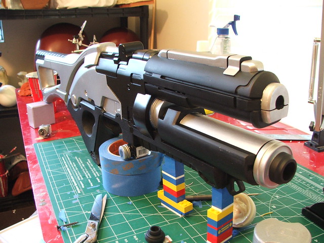
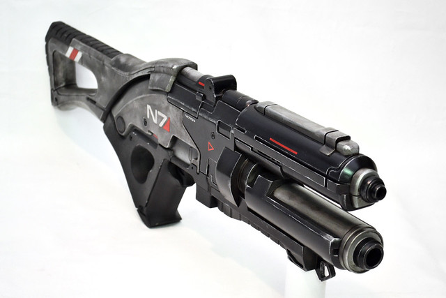
Finally, the rifle was epoxied together into one solid piece! There are three long pins securing the grip into the barrel and rifle body, and a 1″ wide spine runs the entire length of the seam between the rear stock and the rifle body. After the epoxy set, I was able to pick up and handle the rifle by any one of its individual component pieces; even the D-ring on the front grip is functional!
Weathering the rifle was a blast – with heavily worn replicas, this is always my favorite step. If you’re interested in the process, you can check out my time-lapse video detailing the weathering of the M8 Avenger. The process is largely similar, though for the N7, an airbrush was used for some areas.
The final step was a coat of clear, to make sure the acrylic weathering job wouldn’t wear off with the handling the piece would get at Comic-Con. If anyone happens to watch “The Pulse” episodes on Bioware TV, this is the gun that David Silverman is waving around all convention long. I guess he liked it!

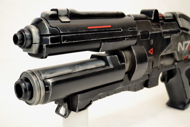
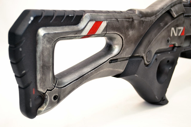
And finally, some beauty shots of the finished product!
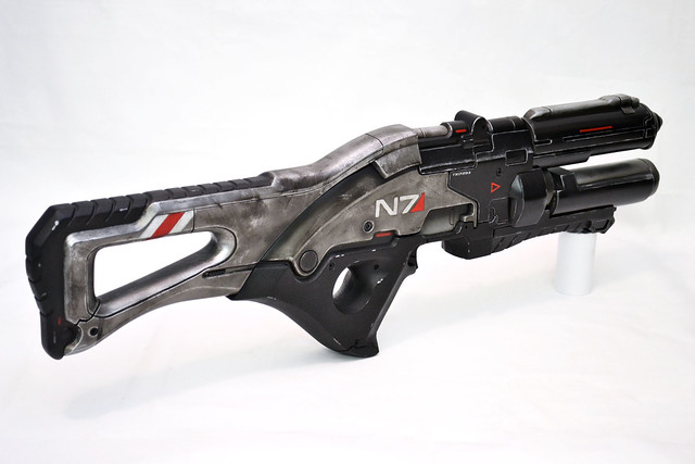
Some more detailed close-ups
There’s many more process photos on my Flickr, and in much higher resolution for those interested in seeing more detail. I may be returning to the world of Mass Effect very soon, so keep an eye here or on my Facebook page (which I try to update as often as possible with WIP shots) for more info.
Thanks for reading!

Daft Punk Helmet (Thomas): Part 2
Ah, where were we?
Right. I had a nice shiny master sculpt ready for molding. This entry will provide some details on the molding process and start laying out the details on the electronics.
To start with, I had to seal off some of the thin areas and unfinished undercuts on the helmet. The bottom side got built up areas around the backsides of the ear cutouts as well as the chin – these were done with clay and some scrap styrene.
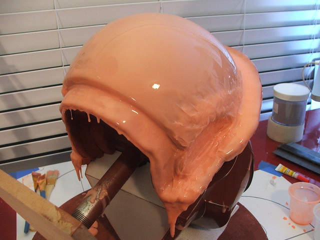
This mold is going to be a 2-part. I learned from the Guy mold that single-piece jacket molds are very difficult to remove the cast parts out of once you’re finished. Thomas’ mold will have a front and a back section, which will make removing final pieces much, much easier.
You can see the clay wall separating the front and back halves in this shot. This pic also shows the first part of molding; a layer of silicone mixed with silicone thinner to create a “print coat” – this helps to ensure no bubbles are trapped in the final mold. I’m using Smooth-On’s Rebound 25 for this piece.
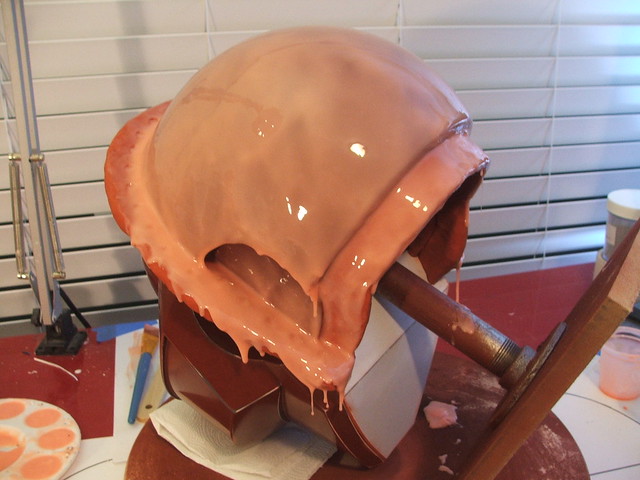
Then the second coat. I added some thickened rubber to the ear indents to build them out a bit
I’m trying something a bit different with the registration keys this time. On Guy, I made them from thickened silicone sculpted into pucks. This works fairly well, but sometimes the rough surface on the pucks themselves causes them to push a couple millimeters out from the mother mold. This time, I took a paint palette and filled it with excess silicone as I was making the first coats.
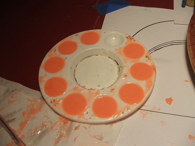
These little egg yolks were popped out when still slightly tacky, and “glued” to a tacky brush coat with some more thickened silicone. Just as a warning, I did get some small air bubbles trapped behind these in a few spots – if you employ my methods, its best to place these in on top of a wet-ish coat of silicone to make sure you don’t get any trapped air.
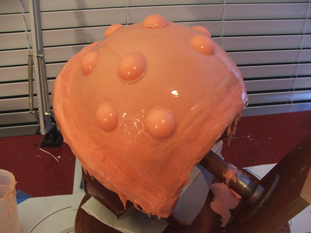
I used 15 of the little bumps in all on the back half, and they’re nice and smooth so hopefully they’ll keep registration better than their hand-sculpted predecessors.
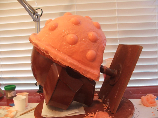
After waiting 24 hours for the back half to dry, I started work on the front. Keep in mind that silicone sticks to silicone, so you’ll need to put something between layers to make sure you don’t glue the halves of your mold together. For separating the two halves, I use this cleaner wax. Smooth-On makes stuff called “Sonite Wax” for this specific purpose, and when this tub runs dry, I might look into that. For now though, this stuff works great.
Make sure to test homebrew stuff like this first! The line of painter’s tape on the helmet in the background is to protect the primer, as this cleaner wax will dissolve it and damage the finish. Always test first!
In prep for molding the front, I added a filler panel underneath and some clay dams along the chin. I also added a small “maker’s mark” which will be trimmed off in the end. Not sure how much plastic will even get to this spot, but oh well.
After that it’s print coat, thickened coat, and keys. Second verse, same as the first.
The MDF seams in this shot will be for the mother mold. These will make a more even flange, ensuring the sections of the mold jacket stay aligned. The front part of the helmet is split into 2 mother mold halves as well – similar to how my Guy helmet has one front section and 2 back halves. This was made from 1/4″ MDF and secured with a crapton of wingnuts and screws.
After setting these in place, I filled in the gaps between the MDF and the mold with clay. This prevents the mothermold material from bridging this gap and fusing into one solid piece
For the mothermold, I decided to use Smooth-On’s Plasti-Paste again. This one is a fair bit thinner and smoother than the one I made for the Guy helmet, so its a lot easier to pull copies.
The mothermold sections removed, showing detail on the inside. The MDF rings make re-aligning the sections much, much easier. I think I’ll be doing this technique from now on.
Interior of the Rebound-25 mold. Great detail. There are a few small areas where some air was trapped under the registration keys – most notably on the right cheek. In the future, putting some thickened silicone underneath these will alleviate this problem. It makes for about a 1/32″ dent in the final casting, but nothing a small spot of filler can’t fix.
First pull!
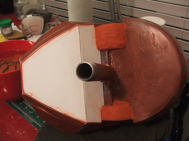
The ear puck molds were much simpler. For these, I used a piece of PVC pipe as a mold jacket and glued the ear puck to a base made out of MDF.

This was filled with Smooth-On’s Mold Max 30. Pop the master out and voila!
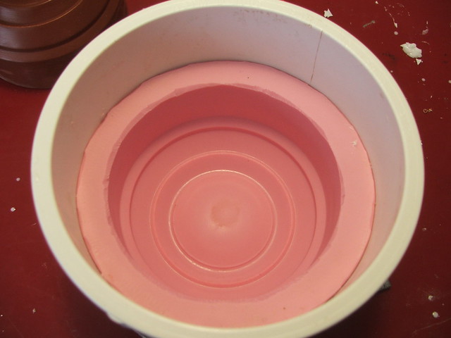
To cast these, I employed a trick I learned when making the barrel for my Portal Gun. To make the ear pucks hollow, I’ve poured about 1/4 cup of resin into the base of the mold and allowed it to cure around a cardboard ring. Once the lower section cures, you fill in the cavity between the ring and the mold, and BAM – hollow cylinder.
Outside of a finished pull
And, lastly, some shots of the helmet with the ears inserted. I can’t tell you how happy I was when they just plunked right into place. Almost as if I knew what the hell I was doing.
The white casting above was done with Smooth On’s Smoothcast 65D rotocasting urethane plastic. This caused issues with the Guy helmets in the past, as part of the chroming process involves a high-heat baking. A byproduct of this was some sagging in the urethane plastic, and I ended up losing about 4 helmets to various deformities. The guys at Creations n’ Chrome did come up with a solution to this issue, and were able to send me a couple flawless pieces by the end of things.
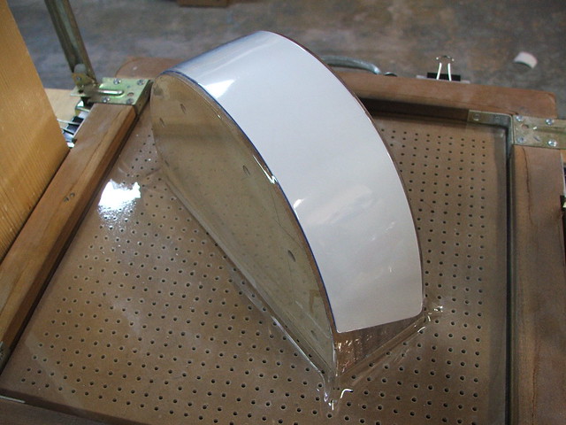
This time though, at the recommendation of my friend David over at 2 Story Props, I decided to try casting in fiberglass and polyester resin. The benefits are much lighter weight castings, much thinner, and nearly impervious to baking heat. David has some good tutorial videos up showcasing his process. You can check these 3 vids out here(1) here (2) and here (3).
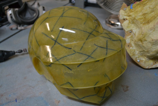
Fiberglass casting is a totally new experience for me, and the cast parts were probably a B+ success. Not bad, but I still have a lot to learn!
The “X” markings are to show me where I’ve laid down a second coat of fiberglass cloth, making sure I’ve got a durable, thick and strong cast.
The ear pucks were done in a similar manner, with a T nut inserted into the fiberglass for mounting them later.

The ears will have the ring of lights embedded into them, so they were cut in half and the base piece was glued into the helmet base. I swear this will make more sense later!
You can see there were a few spots where the helmet needed a little bondo work to get right. The polyester resin pulled away slightly from the mold while I was making it, resulting in odd little dents here and there.

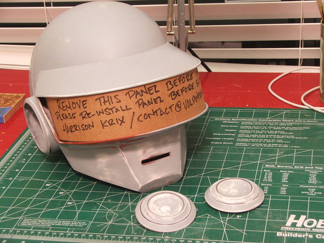
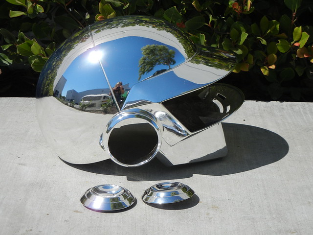
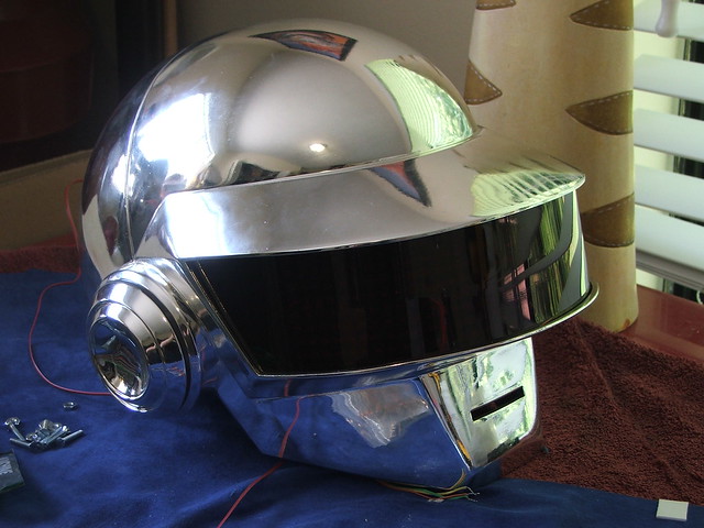
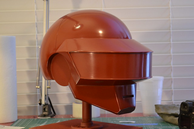
After plenty of sanding, filling, priming, and more sanding, the final coat was wet-sanded down to 2,000 grit and sent off to Creations n’ Chrome for its very special and very shiny topcoat! The cardboard panel in the visor area makes sure that no pressure during shipping is transferred to the thinner areas around the visor and nothing cracks on his cross-country journey.
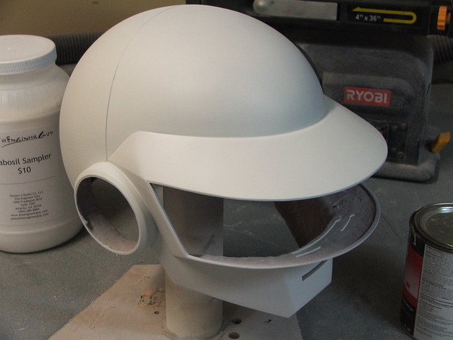
Part 3 will cover the final chromed helmet as well as the most complex electronic project I’ve ever taken on. 496 LEDs! WOO.
As always, there are more pics available on my flickr page. Also be sure to check out my YouTube for updates and videos!
Thanks for reading!

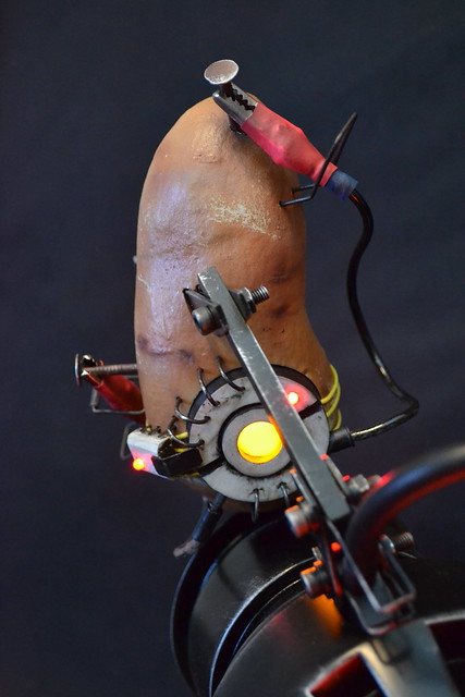
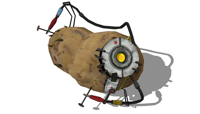
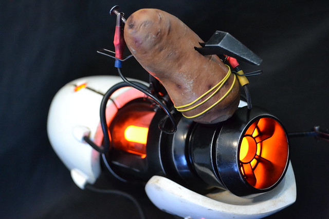
GLaDOS Potato, Portal 2
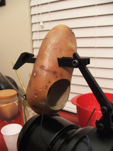
This was a fun project, done as a small add-on to the third (and final!) Portal Gun commissioned by the guys at VALVe Software in Seattle. While the additional potato-GLaDOS wasn’t a requested item, the release of Portal 2 prompted me to put one together before delivery.
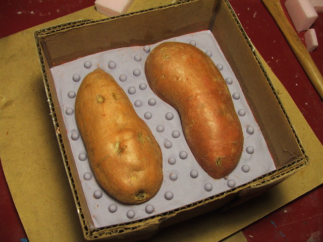
Due to the very short timeframe, I opted against sculpting a potato from scratch. During a grocery shopping trip, my wife scoured the produce department to locate two likely candidates to live on the end of the ASHPD.
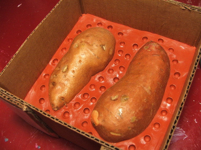
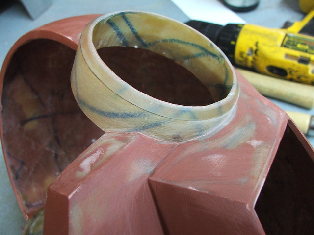
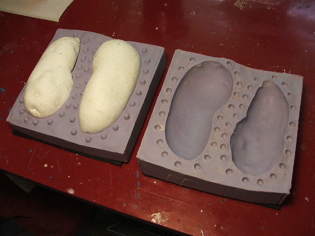
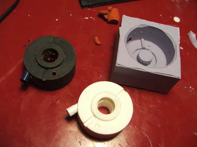
These two spuds were tossed into a mold box and molded in Smooth-On’s Omoo silicone. If you’re noticing the lack of a pour spout, these were designed to be hollow cast pieces. Once resin was added, the potatoes were slush cast in 65D resin to make lightweight replicas.
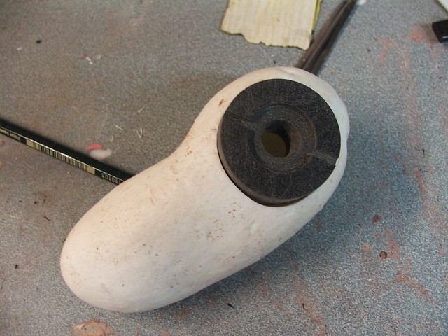
GLaDOS’s “eye” was made on a lathe using laminated sheets of 1/2″ sintra. The oversized chip on the side of the potato was cut from sintra as well.
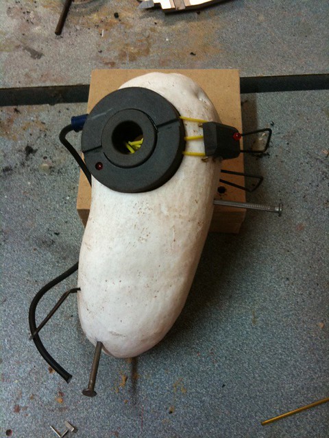
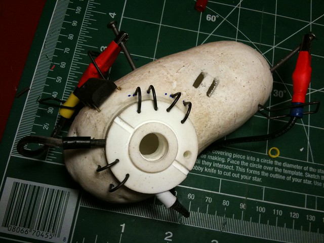
Smaller details were added with wire and roofing nails. The whole of this build is mostly stuff that can be sourced at a local hardware store. In order to keep the scale correct, some things (like the alligator clips) had to be cut down.
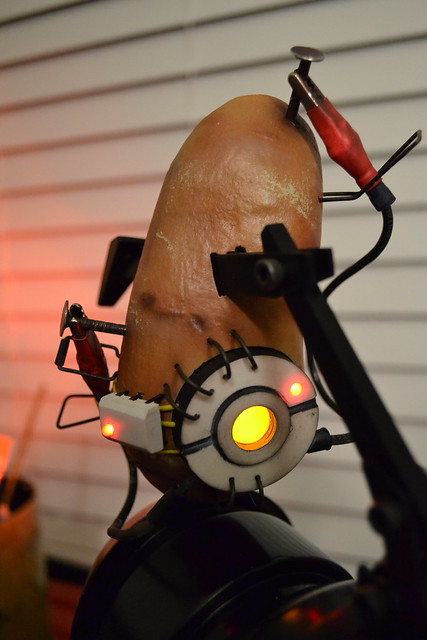
The eye of the potato was molded in more omoo and cast with SmoothCast 300. After this, more wire details were added.
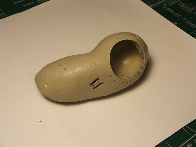
I found a textured Krylon tan paint that worked pretty well for a basecoat. The surface had a sort of satin feel to it.
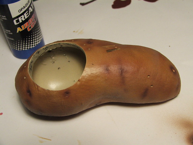
Layers of dirt and discoloration were added with an airbrush and acrylic paint. I found that lightly scraping the high areas with a damp paper towel pulled this color off and simulated peeled potato skin rather well.
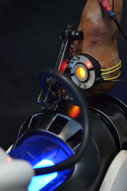
Illumination is controlled by the switches in the back of the Portal Gun itself, and GLaDOS turns on and off with the rest of the illumination. A set of power and ground lines run up through the claw and into the hollow potato for the LEDs
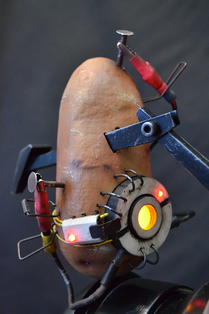
I wish I had taken time to document the rest of the build, because things take a bit of a jump here – unfortunately, my short timeframe meant that I spent more time cranking on the little angry spud and less time behind my camera. Illumination was provided by two 5mm yellow LEDs and two 3mm red. These are routed in the hollow cavity of the potato and shine through the chip and eye area.
More acrylic paint was added to the nails, alligator clips, and eye to weather the piece to match the (by now) ancient Portal Gun.
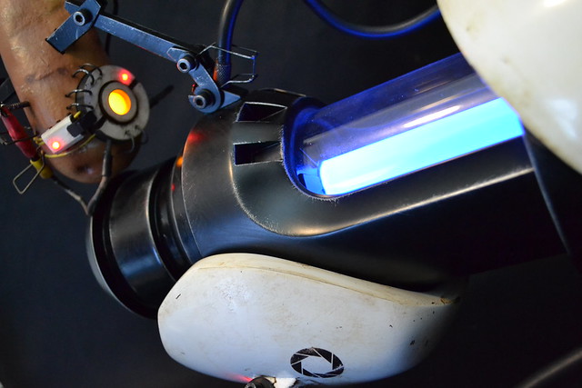
Better video will be coming soon, but potato GLaDOS is capable of speech! Until then, enjoy these final product shots.
The completed gun now lives at VALVe HQ, make sure to say hi if you ever get a chance to visit!
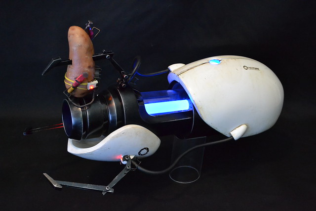
More pics available on my flickr page, thanks for looking!